Advertisement
Quick Links
Shredder Kit Instructions
Warranty:
BYOC, Inc. guarantees that your kit will be complete and that all parts and components
will arrive as described, functioning and free of defect. Soldering, clipping, cutting,
stripping, or using any of the components in any way voids this guarantee. BYOC, INC
guarantees that the instructions for your kit will be free of any majors errors that would
cause you to permanently damage any components in your kit, but does not guarantee
that the instructions will be free of typos or minor errors. BYOC, INC does not
warranty the completed pedal as a whole functioning unit, nor do we warranty any of the
individual parts once they have been used. If you have a component that is used, but feel
it was defective prior to you using it, we reserve the right to determine whether or not the
component was faulty upon arrival. Please direct all warranty issues to:
sales@buildyourownclone.com This would include any missing parts issues.
Return:
BYOC, Inc. accepts returns and exchanges on all products for any reason, as long as they
are unused. We do not accept partial kit returns. Returns and exchanges are for the full
purchase price less the cost of shipping and/or any promotional pricing. Return shipping
is the customer's responsibility. This responsibility not only includes the cost of
1
Advertisement

Related Manuals for BYOC Shredder


Summary of Contents for BYOC Shredder
- Page 1 This would include any missing parts issues. Return: BYOC, Inc. accepts returns and exchanges on all products for any reason, as long as they are unused. We do not accept partial kit returns. Returns and exchanges are for the full purchase price less the cost of shipping and/or any promotional pricing.
- Page 2 That being said, we will do our best to help you as much as we can. Our philosophy at BYOC is that we will help you only as much as you are willing to help yourself. We have a wonderful and friendly DIY discussion forum with an entire section devoted to the technical support and modifications of BYOC kits.
-
Page 3: Table Of Contents
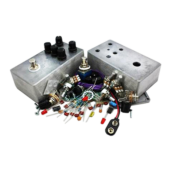
Parts Checklist…………………………..page 5 Populating the Circuit Board…………..page 7 - 12 Assembly………………………………..page 13 Wiring………………………………..page 16 Finish up………………………………..page 22 Operating Overview………………...…..page 23 Schematic...........page 24... - Page 4 This is what your build should look like when it’s done. Your kit may include different color components; this is nothing to worry about as long as the values are correct.
-
Page 5: Parts Checklist
Parts Checklist for The Shredder Kit Resistors: 1 - 100ohm (Brown/Black/Black/Black/Brown) 1 - 1k (brown/black/black/brown/brown) 1 - 3k3 (orange/orang/black/brown/brown) 1 - 4k7 (yellow/purple/black/brown/brown) 1 - 6k8 (Blue/Gray/Black/Brown/Brown) 2 - 10k (brown/black/black/red/brown) 2 - 33k (Orange/Orange/Black/Red/Brown) 3 - 47k (yellow/purple/black/red/brown) 2 - 100k... - Page 6 1 - B25k (Treble) 1 - B100k (Contour) Hardware: 1 - enclosure w/ 4 screws 1 - Shredder circuit board 1 - 3pdt footswitch 5 - knobs 1 - AC adaptor jack 2 - Enclosed jacks (or 1 - Open Stereo Jack (Input) and 1 - Open Mono Jack (Output)
-
Page 7: Populating The Circuit Board
Populating the Circuit Board Step 1: Add all the resistors. Resistors are not polarized, so they can face in either direction. - Page 8 Step 2: Add the diodes. The smaller 1N914 are highlighted in red. The larger 1N4001 is highlighted in yellow. Make sure the stripe on each diode matches with the stripe on the layout.
- Page 9 Step 3: Add the IC socket. Match up the u-shaped notch in the socket with the notch on the layout. If the op amp that is supplied with your kit does not have a notch in it, there will be a small dot in one corner. This denotes pin #1.
- Page 10 Step 4: Add the film and ceramic disc caps. These are not polarized and can go in either direction. The film caps are highlighted in red, the ceramic disc caps are highlighted in yellow.
- Page 11 Step 5: Add the electrolytic capacitors. These are polarized, meaning they have a positive and negative end. The positive end of the cap will have a longer lead and should go in the square solder pad.
- Page 12 Step 8: Add the battery snap. Thread the wires of the battery snap through the holes in the PCB before soldering as shown below.
-
Page 13: Assembly
Main PCB Assembly Step 1: Mount the AC adapter jack to the enclosure. Your kit may come with either an external thread or internal thread. Don’t get confused by this. They still function exactly the same. You just thread the external nut on the outside and the internal nut on the inside. - Page 14 BEFORE CONTINUING, REMOVE THE DUST COVERS FROM THE POTENTIOMETERS. YOU MAY NEED TO MAKE A SLIT IN THE COVER TO RELIEVE ANY VACCUUM BETWEEN THE COVER AND THE POTENTIOMETER. Step 2: Flip the PCB over so that the bottom or solder side is up. Insert the four potentiometers, toggle switch and the LEDs into the bottom side of the PCB.
- Page 15 Step 3: Hold the PCB in one hand so that the component side of the PCB is in the palm of your hand and the bottom side with the pots, toggle switch and LED is facing up. Now use your other hand to guide the predrilled enclosure onto the PCB assembly so that the pots, toggle switch and LED all go into their respective holes.
-
Page 16: Wiring
WIRING Step 6: Connect the TIP (negative) terminal of the DC adapter jack to the eyelet on the PCB labeled “-“. Connect the SLEEVE of the DC adapter jack to the eyelet on the PCB labeled “+” farthest to the right. Connect the battery disconnect terminal of the DC adapter jack to the second eyelet on the PCB labeled “+”... - Page 17 OPEN JACKS Stereo (input) Jack Mono (output) Jack Install the ¼” jacks into the enclosure.
- Page 18 Your kit will include either open jacks or enclosed jacks. The wiring for both is very similar, and will be shown below. Step 7: Install the footswitch. Orient the footswitch so that the flat sides of the solder lugs are like the diagram below. NOTE: There are no actual number markings on the footswitch.
- Page 19 FOOT SWITCH SOLDER LUG DESIGNATIONS Step 8: Insert the foot switch wires into their respective eyelets on the PCB. You can insert them into the top side and solder on the top side as well. The solder pads should be large enough (if you are using a soldering iron that isn’t too big) to allow you to do this without burning the PVC coating on the wires if you are careful.
- Page 20 Finished Wiring With Open Jacks...
- Page 21 Finished Wiring With Enclosed Jacks...
-
Page 22: Finish Up
Installing IC/Finish up Don't forget to add the knobs, put the cover on the enclosure, and apply the bumpers to the cover. -
Page 23: Operating Overview
Operating Overview VOLUME: This controls the volume of the pedal. GAIN: This controls the amount of distortion. TREBLE: This boosts or cuts the treble. BASS: This boosts or cuts the bass. CONTOUR: Essentially a mid control. CCW is full mids. CW is scooped mids. -
Page 24: Schematic
For high resolution schematic visit: http://byocelectronics.com/shredderschematic.pdf... - Page 25 For tech support issues, visit our message board: http://byocelectronics.com/board Copyright 2018 Build Your Own Clone...
Need help?
Do you have a question about the Shredder and is the answer not in the manual?
Questions and answers