Table of Contents
Advertisement
Quick Links
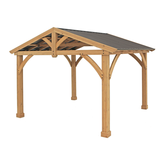
CAROLINA PAVILION
Installation and Operating Instructions – YM11726X
IMPORTANT, RETAIN FOR FUTURE REFERENCE: READ CAREFULLY
Revised 01-09-2019
[39.624 m]
13'
Yardistry – North America
[3352.8]
11'
Toll Free Customer Support:
1.888.509.4382
info@yardistrystructures.com
www.yardistrystructures.com
Height: 10' 1" (3.07 m)
Y40000-726X
Advertisement
Table of Contents

Related Manuals for Yardistry CAROLINA


Summary of Contents for Yardistry CAROLINA
- Page 1 CAROLINA PAVILION Installation and Operating Instructions – YM11726X IMPORTANT, RETAIN FOR FUTURE REFERENCE: READ CAREFULLY Revised 01-09-2019 [39.624 m] 13’ Yardistry – North America [3352.8] 11’ Toll Free Customer Support: 1.888.509.4382 info@yardistrystructures.com www.yardistrystructures.com Height: 10’ 1” (3.07 m) Y40000-726X...
- Page 2 Wood is NOT flame retardant and will burn. Grills, fire pits and chimineas are a fire hazard if placed too close to a Yardistry structure. Consult user’s manual of the grill, fire pit or chimnea for safe distances from combustible materials.
- Page 3 Limited Warranty Yardistry warrants that this product is free from defect in materials and workmanship for a period of one (1) year from the original date of purchase. In addition, for any product with lumber, all lumber is warranted for five (5) years against rot and decay. This warranty applies to the original owner and registrant and is non-transferable.
- Page 4 Instructions for Proper Maintenance Your Yardistry structure is designed and constructed of quality materials. As with all outdoor products it will weather and wear. To maximize the enjoyment, safety and life of your structure it is important that you, the owner, properly maintain it.
- Page 5 Assembly Tips Following are some helpful tips to make the assembly process smooth and efficient. PRE-ASSEMBLIES: (i.e. Post and Beam Assemblies, Roof Rafter Assembly, etc) • Work on a raised, solid and flat surface such as, a table or saw horse. •...
- Page 6 Permanent Installation Examples Note: It is critically important you start with square, solid and level footings, concrete pad or deck to attach your Pavilion. We supply Post Mounts with this structure which gives you the flexibility to permanently install your structure to a pre-existing or new wood or concrete surface.
- Page 7 Permanent Installation Examples cont. Concrete Patio (min. 11’7” x 12’) with 6” clearance on all sides Anchoring Hardware not included Wood Deck (min. 11’ 7” x 12’) with 6” clearance on all sides Anchoring Hardware not included Post Mount Anchoring Hardware (not included) Post Mounts have a 1/2”...
- Page 8 Part Identification ( Dimensions are approximate and are shown to assist in the identification of parts for assembly. Actual dimensions may be smaller or larger. 16pc. (422) Plinth 2pc. (476) Gusset Support 25.4 x 139.7 x 1724mm (1 x 5½ x 67-7/8") 19.1 x 133.4 x 190.5mm (3/4 x 5-1/4 x 7-1/2") Y50131-476 Y50131-422...
- Page 9 Hardware Identification Dimensions are approximate and are shown to assist in the identification of parts for assembly. Actual dimensions may be smaller or larger. 2pc. (477) Gable Upright Front 88.9 x 139.7 x 796.5mm 2pc. (480) Gable Upright Back 76.2 x 139.7 x 813.3mm (3½...
- Page 10 Hardware Identification Dimensions are approximate and are shown to assist in the identification of parts for assembly. Actual dimensions may be smaller or larger. 1/4 x 2-3/4" 4pc. Hex Bolt - (Y07718-223) 1/4 x 2" 10pc. Hex Bolt - (Y07718-220) 1/4 x 4-3/4"...
- Page 11 2pc. Right Side Panel - Y01033-165 6pc. Main Panel - Y01033-164 2pc. Roof Edge Right (Y01033-153) 1pc.Ridge Cap 91 2pc. Ridge Clip (Y01033-117) (Y01033-114) 1pc. Yardistry Plaque (Y70800-104) 1pc. Jamb Mount 1pc. - Post Mount 1pc. Corner Bracket Bracket Set (10Pk) Bracket Set (8Pk) (Y00419-160)
- Page 12 Step 1: Inventory Parts - Read This Before Starting Assembly STOP STOP STOP STOP This is the time for you to inventory all your hardware, wood and accessories, referencing the parts identification sheets. This will assist you with your assembly. •...
- Page 13 Step 2: Post Assemblies Avery Inst 1 - Post Assembly A: At the bottom of one (696) 6 x 6 Post insert two 5/16” T-Nuts as shown in fig. 2.1. B: At the bottom of the same (696) 6 x 6 Post place two Post Mounts tight to the bottom and inside faces as shown in fig.
- Page 14 Step 3: Beam Assembly - Front/Back Savannah Inst 2 - Beam Assembly - Front/Back A: Fit together two (474) Gable Beams so the notched out ends are tight together then place one (477) Gable Upright Front on one side and one (480) Gable Upright Back and one (476) Gusset Support on the other side. Loosely attach with two 5/16 x 4”...
- Page 15 Step 4: Beam Assembly - Side Part 1 A: Fit two (475) Outside Beams together so the middle pilot holes are at the bottom for both. Connect using two 5/16 x 1-1/2” Hex Bolts (with 5/16” lock washer, 1/4-5/16” large washer and 5/16” t-nut) as shown in fig. 4.1. B: Connect one (473) Inside End Beam to each end of one (472) Inside Centre Beam 92 using two 5/16 x 1-1/2”...
- Page 16 Step 4: Beam Assembly - Side Part 2 D: Place one Beam Outside Assembly and one Beam Inside Assembly so the ends are flush. Match the bolt holes in each (473) Inside End Beam with the bolt holes in each (475) Outside Beam. Attach assemblies with 12 Avery Inst 3 - Beam Assembly - Side #8 x 2-1/2”...
- Page 17 Step 5: Frame Assembly and Anchoring Part 1 A: Move your Post Assemblies to the final location. Make sure the ground is flat and level before continuing assembly. B: With one person at each Post stand two complete Post Assemblies. A third person places one Beam Assembly - Side against the outside of each Post, flush to the tops and outside corners.
- Page 18 Step 5: Frame Assembly and Anchoring Part 2 E: Make sure each corner is square and level then attach Beam Assembly - Side to Post Assemblies with one 5/16 x 4-3/4” Lag Screw (with 1/4-5/16” large washer) per corner and Beam Assembly - Front/Back to Post Assemblies with one 5/16 x 3”...
- Page 19 Step 6: Attach Gussets Note: The bevelled ends on each Fig. 6.1 Beam (706) Assembly - gusset should always face away from (705) Gusset Gusset (706) Front/Back Right Left the wood it is attaching to. Gusset Beam Left Assembly - A: Make sure the assembly is still Side (705)
- Page 20 Avery Inst 6A - Frame Roof Panel Step 7: Frame Roof Panel Part 1 A: Lay out 7 (468) Rafters on a hard flat surface as shown in fig. 7.1. You will need lots of room for this step. Avery Inst 6A - Frame Roof Panel B: Place 1 (465) Long Strap on the bottom of five (468) Rafters, flush to the outside edge of the first and centred Savannah Inst 6A - Frame Roof Panel on the last.
- Page 21 Avery Inst 6A - Frame Roof Panel Step 7: Frame Roof Panel Part 2 D: Tight to each (465) Long Strap place one (466) Short Strap and tight to the first (466) Short Strap place one (465) Long Strap. Make sure the wider gap on each strap is on the outside. Make sure the assembly is square, pre-drill the first (466) Short Strap with a 1/8”...
- Page 22 Step 7: Frame Roof Panel Part 3 F: Make sure frame is square. Measurements to be as shown in fig. 7.6. G: In the two middle gaps between (468) Rafters place one (470) Rafter Brace flush to the top of (469) Rafter Top Short and (467) Rafter Top.
- Page 23 STOP STOP STOP STOP INSTALLING ROOFING MATERIAL CAUTION! Roofing material may have sharp edges! Wear gloves! HANDLE WITH CARE! Place roofing material on a non-abrasive surface before assembly as it can bend, dent and scratch easily. WARNING – DO NOT OVER TIGHTEN ROOFING SCREWS! Over tightening screws will cause roofing material to crush.
- Page 24 STOP STOP STOP STOP INSTALLING ROOFING MATERIAL CAUTION! Roofing material may have sharp edges! Wear gloves! BE SURE TO REMOVE ALL PLASTIC COVERING, ON BOTH SIDES OF THE ALUMINUM PANELS AND TRIM, DIRECTLY BEFORE INSTALLING EACH PIECE. (One side is clear and the other is blue, both must be removed.) Example #1 Example #2 Overtightened and Crushed...
- Page 25 Step 8: Attach Roof Panels Part 1 Note: Be sure to remove all plastic covering on both sides of the metal panels directly before installing each piece. A: Make sure panel is still square then on one Roof Panel Frame place one Main Panel flush to the top and sides of the outside (468) Rafter on the side shown below.
- Page 26 Step 8: Attach Roof Panels Part 2 E: Place one Roof Edge Left and one Roof Edge Right on the bottom of one Roof Panel Frame so they meet tight and the ends are flush with the outside ends of (466) Short Strap and (465) Long Strap. Predrill the end hole on Roof Edge Left with a 1/8”...
- Page 27 Step 8: Attach Roof Panels Part 3 F: Attach the three Main Panels and one Right Side Panel to Roof Panel Frame using 48 #8 x 1” Hex Roofing Screws as shown in fig. 8.6. On the left outside (468) Rafter, in between the screw holes, three additonal screws are to be inserted through the panels in the spaces indicated below (see A).
- Page 28 Step 8: Attach Roof Panels Part 4 G: Place Weather Seal on the inside of two Ridge Clip Short then place one Ridge Clip Short flush to each side of Roof Panel Frame and 2-3/4” up from the bottom of (467) Rafter Top and (469) Rafter Top Short, make sure not to compress Weather Seal.
- Page 29 Step 9: Attach Roof Panels to Frame Part 1 A: With four assemblers lift one Roof Panel Frame up and over Post and Beam Frame Assembly so the notches in (468) Rafters rest on Beam Assembly - Side and (467) Rafter Top and (469) Rafter Top Short are flush to the outside of each (480) Gable Upright Back.
- Page 30 Step 9: Attach Roof Panels to Frame Part 2 C: From inside the assembly attach the two Roof Panel Frames together through each (470) Rafter Braces with four 1/4 x 4-3/4” Hex Bolts (with two 1/4-5/16” large washer and one 1/4” lock nut) and through (467) Rafter Tops and (469) Rafter Top Shorts with four 1/4 x 2-3/4”...
- Page 31 Step 9: Attach Roof Panels to Frame Part 3 D: Loosely attach each of the centre (468) Rafters to the inside of each Beam Assembly - Side with one Rafter Beam Bracket per (468) Rafter using one 1/4 x 2” Hex Bolt (with two 1/4-5/16” large washer and one 1/4” lock nut) per bracket.
- Page 32 Step 10: Attach Ridge Caps Part 1 A: Slide Ridge Cap over the Ridge Clips towards the centre of the roof. (fig. 10.1 and 10.2) B: With the swaged end facing in slide one Ridge Cap Short at each end of the roof over the Ridge Clips. Use the swaged end to help push the Ridge Cap to the centre of the roof.
- Page 33 Step 10: Attach Ridge Caps Part 2 C: Make sure the Ridge Cap Shorts are flush to the outside edge of the roof then attach each end of the Ridge Cap to each Ridge Cap Short with two #8 x 3/4” Metal Screws per side. (fig. 10.5, 10.6 and 10.7) Fig.
- Page 34 Step 11: Attach Gable Ends A: On one side of the assembly place two (471) Gable Ends against the outside (468) Rafters so the peaks meet in the centre and they are tight and flush to the top and edge of (477) Gable Upright Front. Bottom of (471) Gable End to bottom of (468) Rafter should measure 1”...
- Page 35 Step 12: Attach Gable Gussets A: From inside the assembly place one (414) Gable Gusset on each side of (480) Gable Upright Back so it is resting on (471) Gable End, tight to (480) Gable Upright Back and tight and flush to (468) Rafter. (fig. 12.1 and 12.2) B: Attach each (414) Gable Gusset to (471) Gable End with two #8 x 1-3/4”...
- Page 36 Step 13: Truss Assemblies Part 1 A: Place one (417) Tie Brace centred, tight and square to the top of (416) Tie. Attach (416) Tie to (417) Tie Brace using two Jamb Mounts (one per side) with four #8 x 1” Pan Screws per mount. Repeat to complete five Tie Brace Assemblies.
- Page 37 Step 13: Truss Assemblies Part 2 C: Attach one Tie Centre Bracket to the peak of four (468) Rafter, (467) Rafter Top, (469) Rafter Top Short with four #8 x 1” Pan Screws per bracket. Notice that three Tie Centre Brackets face one way and one faces the opposite side.
- Page 38 Step 13: Truss Assemblies Part 3 D: With a helper place five (416) Tie with brackets tight against (468) Rafters so (417) Tie Braces fit into Tie Centre Brackets. Make sure (416) Ties are level then attach Tie Wrap Brackets to (468) Rafters with two #10 x 1-1/4”...
- Page 39 Step 13: Truss Assemblies Part 4 F: Secure four (417) Tie Braces to each Tie Centre Bracket with two #8 x 1” Pan Screws per bracket. (fig. 13.9 and 13.10) G: Secure remaining (417) Tie Brace to (467) Rafter Top and (469) Rafter Top Short with one Corner Bracket using four #8 x 1”...
- Page 40 Step 14: Attach Plaque A: Attach Yardistry Plaque to a prominent location on your Pavilion with two #8 x 1” Pan Screws. This provides warnings concerning safety and important contact information. A tracking number is provided to allow you to get critical information or order replacement parts for this specific model.
- Page 41 NOTES support@yardistrystructures.com...
- Page 42 Atención a: Servicio de Atención al Cliente À l’attention de: Service à la clientèle Yardistry would like to say “Thank you” for your time and feedback. Yardistry quiere “Agradecerle” por su tiempo y su opinión. Yardistry aimerait vous remercier d’avoir pris le temps de répondre au sondage.
Need help?
Do you have a question about the CAROLINA and is the answer not in the manual?
Questions and answers