Table of Contents
Advertisement
Quick Links
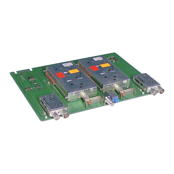
Head-End Digital Modulator
Notes on the Assembly Instructions.
As well as this supplementary Assembly
Instructions, the Assembly Instructions for the
STC 160 apply.
GSS
Grundig SAT Systems GmbH
Beuthener Strasse 43
D-90471 Nuremberg
Terrestrial
HDMT 263
HDMT 265
Phone:
+49 (0) 911 / 703 8877
Fax:
+49 (0) 911 / 703 9210
Email:
info@gss.de
Internet:
www.gss.de
Advertisement
Table of Contents

Related Manuals for GSS HDMT 263


Summary of Contents for GSS HDMT 263
- Page 1 Head-End Digital Modulator Terrestrial HDMT 263 HDMT 265 Notes on the Assembly Instructions. As well as this supplementary Assembly Instructions, the Assembly Instructions for the STC 160 apply. Phone: +49 (0) 911 / 703 8877 Grundig SAT Systems GmbH Fax:...
-
Page 2: Table Of Contents
Channel selection / frequency setting of the HF input .......17 Input frequency, Input channel, Fine-tuning ........17 Fine-tuning ................18 Saving settings ................18 6 Final procedures ..................19 6 Channel and frequency tables ..............20 - 2 - HDMT 263, HDMT 265... -
Page 3: Safety Regulations
I n f o r m a t I o n c o p e o f d e l I v e ry 1 Module HDMT 263 or HDMT 265 1 HF connection cable... -
Page 4: Meaning Of The Symbols Used
Output impedance: ............75 Ω, nominal Bandwidth: ..........7 MHz / 8 MHz (switchable) Channels: HDMT 263 ..........S 9 … S 16, incl. C 5 … C 12 HDMT 265 ..............C 21 … C 69 Frequency range: HDMT 263 ............164 MHz … 269 MHz HDMT 265 ............470 MHz …... -
Page 5: Description
COFDM-modulated signals into two outgoing COFDM-modulated signals with free selectable fre- quency (HDMT 263 –> VHF / HDMT 265 –> UHF, see Technical Data page 4). The COFDM modules are programmed via the head-end station control panel. -
Page 6: Installation
• Insert the COFDM module in grooves of an open slot (with con- tact strip on the board at the rear wall of the housing) . • Gently slide the COFDM module into the head-end station and ensure that it makes contact with the contact strip on the board at the rear wall of the housing. - 6 - HDMT 263, HDMT 265... -
Page 7: Connecting The Cofdm Module
• Terminate unused loop-through outputs with 75 Ω resistors (scope of delivery). Note: At the loop-through outputs the HF signals of the according HF inputs are available. - 7 - HDMT 263, HDMT 265... -
Page 8: The Control Panel At A Glance
I o n s o f t h e c o n t ro l pa n e l b u t to n s – To move the cursor – To adjust values and functions – To store the programmed data – To switch to the next menu - 8 - HDMT 263, HDMT 265... -
Page 9: Programming
I n g The following examples show how the HDMT 265 module is programmed. You can set HDMT 263 in the same way. – To avoid interferences at an activated channel strip a channel must be pro- grammed and a corresponding aerial signal must be connected. -
Page 10: Preparation
LED – Channel strip “A“ Channel strip “B“ • To operate these modules the software version of the control panel must be "V8" or higher. You can find the current operating software on the website "www.gss.de". Level control -20 dB LED – Channel strip “B“ - 10 - HDMT 263, HDMT 265... -
Page 11: Level Setting
≥ 1 dB (s. item "Compare/adjust the HF output level of the channel strips", page 16). • Using the level control (-20 dB), adjust the output level of the modulator of the COFDM module to match the output levels of the modulators of the other LED – modules. Channel strip “B“ - 11 - HDMT 263, HDMT 265... -
Page 12: The Menus At A Glance
Bx 1A BANDWIDTH 8 MHz 7 MHz / 8 MHz Bx 1A INPUT Channel Channel / Freq. Bx 1A INPUT Box 1A INPUT 63 … -64 Fine Bx 1A MEMORY S => STORE CANCEL - 12 - HDMT 263, HDMT 265... -
Page 13: Programming The Module
Bx 1A TWIN-SAT Böx 4 TWIN-SAT Bx 1A DVBT Bx 1B DVBT C5-12,S3-24 C5-12,S3-24 • If necessary, press repeatedly to select the particular module (Bx …) or channel strip "A" or "B" to be programmed. - 13 - HDMT 263, HDMT 265... -
Page 14: Modulator Operating Mode
In this menu, you can choose whether you make the setting for the HF output via channel selection or frequency setting. Bx 1A OUTPUT Bx 1A OUTPUT Channel Freq. • Press to activate channel selection "Channel" or frequency setting "Freq.". • Press the button. - 14 - HDMT 263, HDMT 265... -
Page 15: Output Frequency, Output Channel, Fine-Tuning
Only change the fine-tuning in exceptional circumstances and if there is a well- founded reason for doing so, since once you have changed it, all connected receivers of the cable system must be adjusted to match it by corresponding - 15 - HDMT 263, HDMT 265... -
Page 16: Fine-Tuning
… VHF channels into VHF channels of other frequencies, set the bandwidth to 7 MHz, … UHF channels into VHF channels, set the bandwidth to 8 MHz. Bx 1A BANDWIDTH 8 MHz • Press to set the bandwidth. - 16 - HDMT 263, HDMT 265... -
Page 17: Channel Selection / Frequency Setting Of The Hf Input
Bx 1A INPUT 862.00 • Use the buttons to position the cursor under the digit to be set for the frequency or channel display then use to set the desired output frequency or channel. - 17 - HDMT 263, HDMT 265... -
Page 18: Fine-Tuning
—> By pressing the button, you will be returned to the menu item "Selecting the module / channel strip" (page 13) without saving the programmed data. —> Select additional channel strips for programming if necessary. - 18 - HDMT 263, HDMT 265... -
Page 19: Final Procedures
EMC regulations. • Securely tighten the cable connections (F connectors) using an open-ended spanner (spanner gap 11 mm). • Mount the base plate and the front cover (see STC 160 assembly instruc- tions). - 19 - HDMT 263, HDMT 265... -
Page 20: Channel And Frequency Tables
C 58 770.00 C 68 850.00 C 29 538.00 C 39 618.00 C 49 698.00 C 59 778.00 C 69 858.00 C 30 546.00 C 40 626.00 C 50 706.00 C 60 786.00 - 20 - HDMT 263, HDMT 265... - Page 21 CE - Declaration of Conformity - 21 - HDMT 263, HDMT 265...
- Page 22 Service: Phone: +49 (0) 911 / 703 2221 Fax: +49 (0) 911 / 703 2326 Email: service@gss.de Alterations reserved. Technical data E. & O.E. © by GSS GmbH 02092011...
Need help?
Do you have a question about the HDMT 263 and is the answer not in the manual?
Questions and answers