
Related Manuals for Dräger RS 20


Summary of Contents for Dräger RS 20
- Page 1 RS 20 / RS 80 Reduziereinheit Reducing Unit RS 20 RS 80 Für Zentrale Versorgungsanlagen Gebrauchsanweisung For Medical Gas Pipeline Systems Instructions for Use...
-
Page 2: Table Of Contents
Inhaltsverzeichnis Contents Inhaltsverzeichnis Contents Zu Ihrer und Ihrer Patienten Sicherheit........3 For Your Safety and that of Your Patients ......3 Zweckbestimmung ................ 4 Intended Use ................... 4 Installation..................4 Installation ..................4 Abnahme und Übergabe .............. 5 Testing and Commissioning ............5 Betrieb .................... -
Page 3: Zu Ihrer Und Ihrer Patienten Sicherheit
Zu Ihrer und Ihrer Patienten Sicherheit For Your Safety and that of Your Patients Zu Ihrer und Ihrer Patienten For Your Safety and that of Your Sicherheit Patients Gebrauchsanweisung beachten Strictly follow the Instructions for Use Jede Handhabung an dem Gerät setzt die genaue Kenntnis Any use of the apparatus requires full understanding and strict und Beachtung dieser Gebrauchsanweisung voraus. -
Page 4: Zweckbestimmung
Corrosive, aggressive or toxic gases, Gase, Acetylen, Propan, Butan und acetylene, propane, butane and brennbare Gase. flammable gases. Reduzierstation RS 20 Reducing Station RS 20 Nenndurchfluss 20 m /h bei Vordruck Nominal flow 20 m /h at supply PV = 21 bar und Betriebsdruck pressure PV = 21 bar and operating PB = 5 bar ±0,5 bar*. -
Page 5: Abnahme Und Übergabe
Abnahme und Übergabe Testing and Commissioning Abnahme und Übergabe Testing and Commissioning Bei Verwendung der Reduzierstation For use of the Reducing Station in als Bestandteil der Zentralen Versor- medical gas pipeline systems: gungsanlage: Pressure reducing stations may not be Die Inbetriebnahme der Anlage darf erst operated until they have been tested and nach Abnahme durch sachkundiges commissioned by trained and qualified... -
Page 6: Betrieb
Restdruck von ca. 7 bar in den Gasflaschen. For cylinder manifolds RS 20 / RS 80 a residual pressure of about 7 bar is normal in the gas cylinders on this station. Für gute Be- und Entlüftung im Aufstellungsraum der Fla- Ensure appropriate ventilation in the room where the schenbatterie sorgen –... - Page 7 Betrieb Operation Die Reduzierstation arbeitet mit den bei The Reducing Station operates with the der Inbetriebnahme eingestellten Druck- pressure values set during start-up: werten: 1 Die Manometer zeigen den Druck 1 The gauges indicate the pressure of der linken bzw. rechten Flaschenbat- the left and the right cylinder mani- terieseite an –...
-
Page 8: Betrieb Mit Kaltvergaser / En-Set / 3. Quelle (Reserve)
Betrieb Operation Betrieb mit Kaltvergaser / EN-Set / 3. Quelle (Reserve) Operating with VIE / EN set / 3rd source (reserve supply) Betrieb mit Kaltvergaser / EN-Set / Operating with VIE / EN set / 3. Quelle (Reserve) 3rd source (reserve supply) oder / or: 7 oder / or: 9 1 Die Manometer zeigen den Druck der linken bzw. - Page 9 Betrieb Operation Betrieb mit Kaltvergaser / EN-Set / 3. Quelle (Reserve) Operating with VIE / EN set / 3rd source (reserve supply) Kaltvergaserdruck bis 15 bar: VIE pressure under 15 bar: Der Kaltvergaser speist mit ca. 15 bar im Umschalt- The VIE delivers a pressure of approx.
-
Page 10: Gasflaschen Wechseln
Betrieb Operation Gasflaschen wechseln Replacing Gas Cylinders Gasflaschen wechseln Replacing Gas Cylinders Immer alle Gasflaschen der leeren All the gas cylinders in an empty Flaschenbatterieseite auswechseln. cylinder manifold must be replaced at the same time. Dazu: To do so: Flaschenventile schließen. Close each cylinder valve. -
Page 11: Anlage Außer Betrieb Nehmen
Betrieb Operation Anlage außer Betrieb nehmen Shut-down Anschlussbögen an die Flaschenven- Screw connecting bends to the tile schrauben. cylinder valves. Bei Handanschlüssen die Überwurf- For hand connections, lightly screw mutter von Hand bis zum Anschlag the cap nut on by hand as far as it will leicht aufschrauben. -
Page 12: Instandhaltungsintervalle
Instandhaltungsintervalle Maintenance Intervals Instandhaltungsintervalle Maintenance Intervals Täglich: Daily: Im Dauerbetrieb befindliche Flaschenbatterieanlagen Cylinder manifolds in continuous use must be visually durch Sichtkontrolle auf Betriebsbereitschaft prüfen. checked for correct operation. Es soll immer die Batterieseite mit dem geringeren Druck in Operation should always be effected from the manifold with Betrieb sein. -
Page 13: Fehler-Ursache-Abhilfe
Fehler-Ursache-Abhilfe Fehler-Ursache-Abhilfe Fehler Ursache Abhilfe Betriebsdruck bricht zusammen Ausfall der Gasversorgung Notversorgung einrichten. Gasverbrauch reduzieren. Flaschen leer? Wenn ja, auswechseln. Flaschenventile zu? Wenn ja, öffnen. Von Fachleuten instandsetzen lassen. Betriebsdruck ist zu niedrig Gasversorgung unzureichend Notversorgung einrichten. (P3 < 4 bar) Gasverbrauch reduzieren. - Page 14 Fehler-Ursache-Abhilfe Fehler Ursache Abhilfe Umschaltung schaltet ständig hin und Reserve wird verbraucht Gasverbrauch reduzieren. Manometer beobachten. Seite mit höherem Druck absperren, damit die Seite mit niedrigerem Druck speist. Nach Leermeldung: Seite mit höherem Druck wieder öffnen und leere Flaschen wechseln. Von Fachleuten instandsetzen lassen.
-
Page 15: Fault-Cause-Remedy
Fault-Cause-Remedy Fault-Cause-Remedy Fault Cause Remedy Breakdown in operating pressure Breakdown of gas supply Establish emergency supply. Reduce gas consumption. Cylinder empty ? If yes, replace. Cylinder valve closed ? If yes, open. Have repaired by experts. Operating pressure too low Inadequate gas supply Establish emergency supply. - Page 16 Fault-Cause-Remedy Fault Cause Remedy Change-over switches constantly to and Reserve supply will exhaust Reduce gas consumption. Observe pressure gauge. Shut off side with higher pressure, for use the side with lower pressure. After empty message: open side with higher pressure and replace empty cylinders.
-
Page 17: Technische Daten
15 bar for operation with Kaltvergaser Betriebsdruck P 5 bar Operating pressure P 5 bar Nenndurchfluss Nominal flow RS 20 20 m RS 20 20 m bei P = 21 bar at P = 21 bar = 5 bar ±0,5 bar = 5 bar ±0,5 bar... -
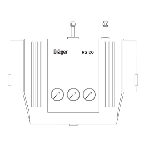
Page 18: Was Ist Was
Was ist was What’s What Was ist was What’s What Reduzierstation RS 20: RS 20 Reducing Station: 1 Ausgang Verteilernetz AVN 1 Pipeline system outlet AVN 2 Druckminderer 2. Stufe DM3 2 Pressure reducer, 2nd stage DM3 3 Anschluss Abblaseleitung... - Page 19 Was ist was What’s What Reduzierstation RS 80: RS 80 Reducing Station: 1 Ausgang Verteilernetz AVN 1 Pipeline system outlet AVN 2 Druckminderer 2. Stufe DM3 2 Pressure reducer, 2nd stage DM3 3 Abblasestutzen 3 Connection vent pipe 4 Druckschalter rechts S2 4 Pressure switch, right S2 5 Hochdruckanschluss rechts 5 High pressure connector, right...
- Page 20 Was ist was What’s What Zubehör für die Reduzierstation: Accessories for Reducing Station: 1 Flaschenhalter 1 Cylinder bracket 2 Gasflasche FL 2 Gas cylinder FL 3 Flaschenventil FV 3 Cylinder valve FV 4 Entlastungsleitung 4 Exhaust pipe 5 Anschlussbogen 5 Connecting bend 6 Entlastungsventil EV 6 Exhaust valve EV 7 Sammelrohr...
-
Page 21: Bestell-Liste Verschleißteile
Bestell-Liste Verschleißteile Order-List Replacement Parts Bestell-Liste Verschleißteile Order-List Replacement Parts Benennung und Beschreibung Sach-Nr. Designation and description Order No. Gummiring R 21 399 Rubber washer R 21 399 für Anschlussbogen und Doppelan- for connecting bend and double schlussbogen (Seite zum Flaschenventil – connectors (manifold cylinder valve –... -
Page 22: Funktionsbeschreibung
Funktionsbeschreibung Functional Description Funktionsbeschreibung Functional Description Fließbild Flow chart EN-Set Abblaseventil am Druckminderer DM1 Blow-off valve on pressure reducer DM1 Abblaseventil am Druckminderer DM2 Blow-off valve on pressure reducer DM2 DM1 Druckminderer 1. Stufe links DM1 Pressure reducer, 1st stage left DM2 Druckminderer 1. - Page 23 Funktionsbeschreibung Functional Description Normalbetrieb: Normal operation: Die Reduzierstation reduziert den Druck der Flaschenbatterie The Reducing Station reduces the pressure of the cylinder von max. 200 bar in zwei Stufen auf einen Betriebsdruck von manifold in two stages from a maximum of 200 bar to an ca.
- Page 24 Funktionsbeschreibung Functional Description 3. Quelle (Reservebetrieb): 3rd source (reserve supply): Im Normalbetrieb muss der Kugelhahn V2 geschlossen sein. Ball valve V2 must be closed in normal operation. Bei Ausfall der Flaschenbatterieseite (2. Fehlerfall) erfolgt The 3rd source is connected manually by opening ball valve eine manuelle Zuschaltung der 3.
- Page 28 Richtlinie 93/42/EWG Directive 93/42/EEC über Medizinprodukte concerning Medical Devices 90 29 247 - GA 6941.125 de/en 90 29 247 - GA 6941.125 de/en © Dräger Medical GmbH © Dräger Medical GmbH Ausgabe/Edition: 7 – 2015-01 Edition: 7 – 2015-01 Änderungen vorbehalten Subject to alteration Ab 2015-08: As of 2015-08:...
Need help?
Do you have a question about the RS 20 and is the answer not in the manual?
Questions and answers