Table of Contents
Advertisement
Quick Links
Advertisement
Table of Contents

Subscribe to Our Youtube Channel
Related Manuals for DOMUSA TEKNIK Fusion Hybrid Oil


Summary of Contents for DOMUSA TEKNIK Fusion Hybrid Oil
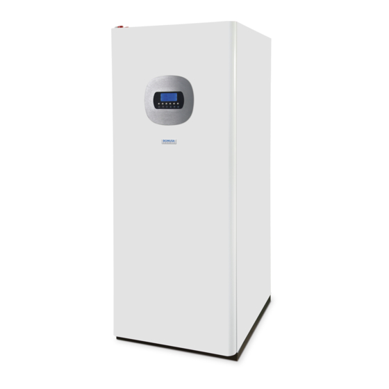
- Page 1 INSTALLATION AND OPERATING INSTRUCTIONS FUSION HYBRID OIL MODULE...
- Page 2 Thank you for choosing a DOMUSA TEKNIK heating boiler. You have chosen the Fusion Hybrid Oil model from the DOMUSA TEKNIK product line. This is a hydraulic module for the “all-in-one” storage of domestic hot water and heating support, which in...
-
Page 3: Table Of Contents
CONTENTS Page SAFETY WARNINGS ..............................3 1.1 S ....................................3 AFETY SYMBOLS 1.2 O ....................................3 THER SYMBOLS 1.3 S ....................................3 AFETY WARNINGS 1.4 G ..............................4 ENERAL INSTALLATION GUIDELINES 2 LIST OF COMPONENTS ..............................5 3 CONTROL COMPONENTS .............................. - Page 4 Fusion Hybrid Oil 16 BURNER..................................... 35 16.1 A ......................................35 SSEMBLY 16.2 B ................................... 35 URNER START 16.3 A ....................................35 DJUSTMENT 16.4 P ................................35 RIMARY AIR ADJUSTMENT 16.5 C ..............................36 OMBUSTION LINE ADJUSTMENT 16.6 C .............................. 36 ...
-
Page 5: Safety Warnings
1 SAFETY WARNINGS 1.1 Safety symbols All safety messages indicate a potential risk of breakdown or damage. Follow the instructions carefully to prevent accident or damage. DANGER This symbol warns of operations or situations involving imminent danger and which could cause severe damage or even death if they are not avoided. -
Page 6: General Installation Guidelines
TEKNIK shall not be held liable for any damage that may occur due to failure to follow these instructions. The Fusion Hybrid Oil module can only be installed in combination with a heat pump from the DUAL CLIMA line from DOMUSA TEKNIK. The FUSION module, in combination with a DUAL CLIMA heat pump, is suitable for use in both heating and cooling installations, and can be combined with fan coils, underfloor heating/cooling and low-temperature radiators. -
Page 7: List Of Components
2 LIST OF COMPONENTS 1. Burner. 12. DHW expansion vessel. 2. Boiler body. 13. DHW safety valve. 3. Support pump shim. 14. DHW tank bulb holder. 4. 3-way diverter valve (G1). 15. Heating expansion vessel. 5. Thermomanometer. 16. Water pressure switch. 6. -
Page 8: Control Components
Fusion Hybrid Oil 3 CONTROL COMPONENTS 20. Heating control thermostat in boiler mode ( 23. Heating operation mode selector ( With it, it is possible the heating working With it, it is possible to select the heating temperature the in boiler by stopping the operation mode. -
Page 9: Installation Instructions
4 INSTALLATION INSTRUCTIONS The Fusion Hybrid Oil module can only be installed in combination with a heat pump from the DUAL CLIMA line, supplied by DOMUSA TEKNIK. Therefore, for its operation, these devices should be connected to each other, both hydraulically and electrically. In this section, the necessary operations for said connection are described in detail. -
Page 10: Hydraulic Installation Of A Support Pump (C4)
- The Fusion Hybrid Oil hydraulic module is an accessory that should be installed in combination with a DUAL CLIMA heat pump for its correct operation. Therefore, in addition to the recommendations described above, it must comply with those indicated in the heat pump installation manual. -
Page 11: Electrical Connections
DUAL CLIMA heat pump to the inside of the Fusion Hybrid Oil module. The module has a series of cable glands at the rear, through which it is possible to insert these cables into the equipment. - Page 12 DUAL CLIMA heat pump to the inside of the Fusion Hybrid Oil module on terminals 27 and 28. Finally, the support circulation pump C4 will be connected to terminals 29 and 30 of the module terminal block (see "Electrical...
-
Page 13: Assembly Of The Dhw Probe
4.6 Assembly of the DHW probe For the correct operation of the Fusion Hybrid Oil hydraulic module, the DHW probe, supplied in the DUAL CLIMA heat pump, must be inserted in the bulb sheath provided in the module tank. This probe is located inside the machine and is identified as “DHW TANK SENSOR”. -
Page 14: Assembly And Connection Of The Control Panel
The control panel is supplied inside the heat pump and must be mounted on the front of the Fusion Hybrid Oil hydraulic module. To do this, open the module door and access the control panel holder located in the rear part. For its correct assembly, please carefully follow the following steps: 1.- Open the door of the Fusion Hybrid Oil module and loosen... -
Page 15: Configuring The Heat Pump
To do this, pass the cable that is supplied inside the heat pump (located alongside the probe harness) to the interior of the Fusion Hybrid Oil module. The hydraulic module has a series of cable glands at the rear, through which it is possible to insert such cables into the module. -
Page 16: Starting Up The Boiler
Once the installation is full, close the disconnector valves. The module Fusion Hybrid Oil is equipped with a security water pressure switch set at a pressure of 0,5 bar, which does not allow the module to start until that pressure is reached in the installation. -
Page 17: Connecting The Room Thermostat ("Auto" Mode)
5.5 Connecting the room thermostat (“AUTO” mode) The Fusion Hybrid Oil module is prepared for the connection of up to 2 room programmable “Connection Diagram” thermostats or room thermostats (see ), which will activate or stop the heating and/or cooling service of the heating/air-conditioning installation, turning off the heat pump and the supporting module when the desired temperature is reached in the home and turning it on when it comes down again. - Page 18 Fusion Hybrid Oil Terminals 33, 34 and 35 are supplied from the factory with a jumper wire connected to each of them, so in order to install this type of thermostat, it will be necessary to remove both jumper wires...
- Page 19 select the temperatures of each of them, in such a way that they do not cross and to avoid that both thermostats are activated at the same time. Terminals 33, 34 and 35 are supplied from the factory with a jumper wire connected to each of them, so in order to install the thermostats, it will be necessary to remove both jumper wires and connect the thermostats as described in the following figure: 33 34 35...
-
Page 20: Start-Up
Fusion Hybrid Oil Heating thermostat (Heating Mode) 33 34 35 33 34 35 Cooling thermostat (Cooling Mode) 33 34 35 33 34 35 5.6 Start-up In order for the warranty to be valid, the module must be started up by an official DOMUSA TEKNIK Technical Assistance Service. -
Page 21: Installation Hand-Over
5.7 Installation hand-over After the initial start-up, the Technical Assistance Service will explain to the user how the module functions, making any observations they consider relevant. The installer is responsible for clearly explaining to the user the functioning of any control or regulation device forming part of the installation but not supplied with the boiler. -
Page 22: Operation
6.2 Operation in “auto” mode This will be the default operating mode of the Fusion Hybrid Oil module (with the ACS selector (23) and the heating selector (22) in auto position. In this mode, the operation will be managed by the DUAL CLIMA heat pump, as indicated in the instruction manual of the heat pump according to “Configuration of auxiliary or supporting energy sources”... -
Page 23: Operation With The Dhw Selector (23)
(23) 6.3 Operation with the DHW selector (23) By turning the DHW selector to position the supporting module becomes the main energy source for the DHW demand. The heat pump stops managing the production of DHW, leaving the heating and production of DHW to the module. The DHW temperature for this operating mode will become the maximum selectable in the heat pump. -
Page 24: Operation With Room Thermostat
DHW demand. 6.5 Operation with room thermostat The Fusion Hybrid Oil module features a connection prepared for the installation of a room “Connecting the room thermostat” in this thermostat or programmable thermostat ( see manual). -
Page 25: Safety Interlocks
Assistance Service. 10 MODULE MAINTENANCE To keep the module in perfect working condition, a review must be carried out annually by personnel authorised by DOMUSA TEKNIK. Module and flue maintenance The most important aspects to be checked are as follows: - The water pressure in the heating/air conditioning installation, when the water is cold, must be between 0.1 and 0.15 MPa (1 and 1.5 bar). -
Page 26: Combustion Adjustment
DOMUSA TEKNIK will hold no liability for any damage caused by unsuitable handling of the power regulation elements of the boiler carried out by personnel not authorised by the company. -
Page 27: Characteristics Of The Circulating Pump
12 CHARACTERISTICS OF THE CIRCULATING PUMP The characteristics and features of the circulating pump are described below. 12.1 Characteristics of the SC pump 12.2 Symbols Light-emitting diodes (LED) - Warning indication: - The LED comes up green in normal operation. - The LED comes up/flashes in case of failure. -
Page 28: Adjustment Modes
1 – Constant speed I, II, III (traditional mode): The pump operates at a constant, pre-set speed. This is the standard operating mode of the pump in the Fusion Hybrid Oil module at speed II. 2 – Variable differential pressure (∆p-v): The setpoint value of the differential pressure H increases in a straight line between ½H and H... -
Page 29: Functions
The standard operating mode of the circulation pump for the Fusion Hybrid Oil Module is with constant speed adjustment at speed II. 12.4 Functions Drainage - Fill and drain the installation correctly. If the pump is not drained automatically: - Activate the drain function by means of the operating button, hold the button for 3 seconds and then release. - Page 30 Fusion Hybrid Oil Characteristic curve of the circulation pump for the constant speed mode I, II, III: PARA Constant speed H (m) Characteristic curve of the circulation pump for the variable differential pressure mode: PARA ∆p-v (Variable differential pressure) H (m) Characteristic curve of the circulating pump for the constant differential pressure mode: PARA ∆p-c (Constant differential pressure)
-
Page 31: Load Losses
12.5 Load losses. -
Page 32: Diagrams And Measurements
Fusion Hybrid Oil 13 DIAGRAMS AND MEASUREMENTS Connection IC: Heating/Cooling Flow, Ø22 1” M RC: Heating/Cooling Return, Ø22. 1” M IBC: Heat Pump Flow, Ø22 1” M RBC: Heat Pump Return, Ø22 1” M ES: Domestic cold water input. 3/4" M SS: Domestic hot water outlet. -
Page 33: Technical Characteristics
14 TECHNICAL CHARACTERISTICS FUSION HYBRID OIL Boiler type Low temperature (heating + DHW by storage) Rated heat output Prated Useful heat output 28.1 Useful heat output (30%) Seasonal energy efficiency of heating Ƞ % (PCI) 91.5 Useful efficiency Ƞ % (PCS) 86.3... - Page 34 Fusion Hybrid Oil FUSION HYBRID OIL Water pressure drop mbar Fume temperature ºC Volume on fume side 0.114 Maximum fume flow kg/s 0.0132 Pressure drop of the fumes mbar 0.17 Combustion chamber length Combustion chamber type Wet, with three exhaust ducts...
-
Page 35: Electrical Diagram
15 ELECTRICAL DIAGRAM G1S: Heat Pump G1 Connection F: Live wire. N (BC): Heat Pump Neutral N: Neutral. V3V E1: Heating/DHW supporting 3-way valve. BC: Circulating pump. E1L: DHW supporting connection. TS: Safety thermostat. E1N: DHW supporting connection. TAF: Cooling Room Thermostat. E2L: Heating supporting connection. - Page 36 Fusion Hybrid Oil C: Input signal from the cooling room Sel CAL: Heating selector. thermostat to the heat pump. C4L (IN): “C4L” input signal of the heat pump. H: Input signal from the heating room Support pump signal. thermostat to the heat pump.
-
Page 37: Burner
16 BURNER 16.1 Assembly Fit the intake and return tubes, inserting the oil filter in the intake tube. 16.2 Burner start-up The “Domestic” burner is equipped with a self-extracting pump to enable fuel intake from a tank installed at a lower level than the burner, providing that the pressure difference measured with the vacuum gauge at the pump does not exceed 0.4 bar (30 cmHg). -
Page 38: Combustion Line Adjustment
Fusion Hybrid Oil 16.5 Combustion line adjustment To adjust the combustion line, loosen the combustion line blocking screw “BL”. Turn the line regulator “RL” clockwise to increase the airflow and anticlockwise to decrease it. After adjustment, tighten the combustion line blocking screw “BR”. -
Page 39: Technical Specifications
Electric voltage 220 V - 50 Hz 16.9 Recommended nozzle and pump pressure The Fusion Hybrid Oil module is supplied with the burner mounted, with its corresponding nozzle and a standard pre-adjustment. The following table specifies the nozzle and corresponding adjustments:... -
Page 40: Electrical Diagrams
Fusion Hybrid Oil 16.11 Electrical diagrams S3 T2 T1 B4: Time meter contact. LB: External cut-off light. S3: Cut-off light contact. FR: Photocell. TC: Boiler thermostat. TR: Transformer. TS: Safety thermostat. MB: Motor pump. CH: Time meter. MB': Auxiliary motor pump. -
Page 41: Electrical Diagrams
16.12 Electrical diagrams To connect and disconnect the red oil intake tube to the nozzle, proceed as follows: Press the connector ring in the direction of the arrow, pulling on the red tube at the same time. TUBO ROJO PRESIONAR GASOLEO ANILLO RACOR DE CONEXION RAPIDA... -
Page 42: Burner Error Code
Fusion Hybrid Oil 16.14 Burner error code We have already mentioned that the burner is equipped with a cut-out system, indicated by the reset button light. It may cut out accidentally, and in this case the steady red light on this button will come on. -
Page 43: Spares List
17 SPARES LIST FUSION HYBRID OIL Tank Pos. Code Designation CTOT000076 Self-locking hex nut M8 SCHA000938 Base grill CTOR000106 Screw Hex cable DIN-933 M8 X16 SCHA000941 Expansion vessel fixing SCON002129 Hot water tank SCOB013036 DHW pipe SCON001275 Drain valve CTOR000092... - Page 44 Fusion Hybrid Oil FUSION HYBRID OIL Boiler Pos. Code Designation Pos. Code Designation SAIS000422 Bottom side insulation SELEDCL000 Electrical board SAIS000424 Rear side insulation Flat allen head screw DIN 7991 CTOR000316 M3 X10 SEXT000743 Left side panel CTOR000253 Screw Head Allen flat screw DIN 7991...
- Page 45 FUSION HYBRID OIL Plumbing...
- Page 46 Fusion Hybrid Oil Pos. Code Designation CFOV000048 Telescopic fitting 3/4” SCOB011706 Drainage tube CVAL000034 Drain valve SCOB013077 Heat pump outlet CFOV000162 Belpa gasket 1” SCON002342 Spool set SCOB013097 Spool SCOB013076 Pump valve SCOB013066 Radiator return SCOB013056 Top valve return CVAL000068...
- Page 47 Burner Pos. Code Designation Pos. Code Designation CFER000074 Cable duct CTOE000065 Counter thread M-M 1/4” CFER000190 Drum cover CQUE000055 Oil filter SCHA002156 Line fixing CTOR000007 Elbow connector 4 x 2.7 g1/8” CTOE000063 Burner line CQUE000011 Suntec oil pump CQUE000022 Turbulator disc CQUE000088 Danfoss oil pump CQUE000019...
- Page 48 Fusion Hybrid Oil FUSION HYBRID OIL Electrical board Pos. Code Designation Pos. Code Designation SEPO003191 Drawer CELC000021 Knob clamp CELC000215 Fixed setpoint thermostat 70° CELC000005 Knob 90º CELC000466 Fixed setpoint thermostat 52° CELC000429 Flat band CELC000547 Fixed setpoint thermostat 60°...
- Page 49 NOTES: ......................................................................................................................................................................................................................................................................................................................................................................................................................................................................................................................................................................................................................................................................................................................................................................................................................................................................................................................................................................................................................................................................................................................................................................................................................................................................................................................................................................................................................................................................................................................................................................................
- Page 50 Fusion Hybrid Oil NOTES: ............................................................................................................................................................................................................................................................................................................................................................................................................................................................................................................................................................................................................................................................................................................................................................................................................................................................................................................................................................................................................................................................................................................................................................................................................................................................................................................................................................................................................................................................................................................................................
- Page 51 NOTES: ......................................................................................................................................................................................................................................................................................................................................................................................................................................................................................................................................................................................................................................................................................................................................................................................................................................................................................................................................................................................................................................................................................................................................................................................................................................................................................................................................................................................................................................................................................................................................................................................
- Page 52 FACTORY & OFFICES Apartado 95 Bº San Esteban s/n 20730 AZPEITIA 20737 RÉGIL (Gipuzkoa) Tel: +34 943 813 899 www.domusateknik.com *CDOC002009* DOMUSA TEKNIK reserves the right to introduce, without prior notice, any change in the characteristics of its products. CDOC002062 05/20...
Need help?
Do you have a question about the Fusion Hybrid Oil and is the answer not in the manual?
Questions and answers