
Subscribe to Our Youtube Channel
Related Manuals for DOMUSA TEKNIK HDEEM SERIES


Summary of Contents for DOMUSA TEKNIK HDEEM SERIES
-
Page 1: Installation And Operating Instructions
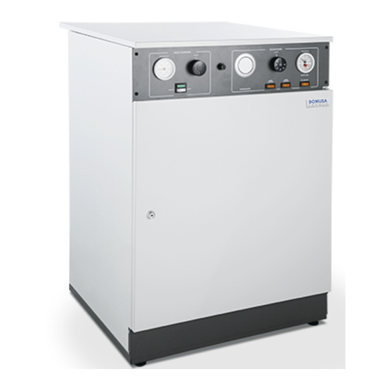
INSTALLATION AND OPERATING INSTRUCTIONS HDEE HDEEM CGM-04/392 ER-0170/1996 ER-0170/1996... - Page 2 Thank you for choosing a DOMUSA TEKNIK electric boiler. From the range of DOMUSA TEKNIK's products you have chosen the HDEE model. With a suitable hydraulic installation, this boiler will provide the ideal level of comfort for your home. This manual forms an essential part of the product and it must be given to the user.
-
Page 3: Table Of Contents
CONTENTS Page 1 LIST OF COMPONENTS ..................................2 2 CONTROL COMPONENTS ................................3 3 IMPORTANT INFORMATION................................4 3.1 W .................................. 4 HO THIS BOOKLET IS FOR 3.2 R ................................... 4 ECOMMENDATIONS 3.3 A ..................................4 PPLICABLE LEGISLATION 3.4 W ......................................4 ARNINGS 4 INSTALLATION INSTRUCTIONS.............................. -
Page 4: List Of Components
HDEE / HDEEM 1 LIST OF COMPONENTS HDEE HDEEM Modular control. Heating Element. Expansion vessel. Heating pump. Automatic air vent. Pressure relief valve. Pressure switch. -
Page 5: Control Components
2 CONTROL COMPONENTS 4. Boiler control thermostat: 1. Safety thermostat “E”: Allows to select the desired boiler set point This is a cut-out mechanism to ensure the temperature to be selected, deactivating the boiler temperature does not exceed 110 ºC. element when the set point temperature is 2. -
Page 6: Important Information
Boiler installation and maintenance must be carried out by qualified technicians, in accordance with applicable legislation. DOMUSA TEKNIK shall hold no liability for any damages caused by incorrect installation or incorrect use of the appliance or accessories. - DOMUSA TEKNIK reserves the right to modify the technical characteristics and components of its products without prior notice. -
Page 7: Installation Instructions
4 INSTALLATION INSTRUCTIONS Fitting measurements HDEEM HDEE Wall mounting system (for HDEEM) 300±15 mm... -
Page 8: Hydraulic Installation
HDEE / HDEEM 4.1 Hydraulic installation Choose a location complying with the conditions required by applicable law. If the boiler is located on a lower level than any of the heating water pipes, it is recommended to fit shut-off valves to the flow and return pipes, to avoid having to drain the installation when maintenance work is carried out on the boiler. -
Page 9: First Start-Up
5 FIRST START-UP 5.1 Filling the installation Use a filling valve to fill the installation slowly until the pressure shown on the thermohydrometer is between 1 - 1.5 bar. 5.2 Checking the circulating pump functioning Unscrew the circulating pump cap so that the rotation shaft is visible. Connect the boiler main switch and check if the pump shaft is turning. -
Page 10: Functioning With Timer (Optional)
HDEE / HDEEM 8 FUNCTIONING WITH TIMER (OPTIONAL) The boiler may optionally be supplied with a timer, which can be fitted to the main control panel. Both (X12) the boiler and the timer are equipped with a quick fixing system using the 12-way connector shown on the electrical diagram. -
Page 11: Diagrams And Measurements
11 DIAGRAMS AND MEASUREMENTS HDEE IC VS HDEEM IC: Heating Output, HDEEM 1" F, HDEE 3/4" M. RC: Heating Return, HDEEM 3/4" M, HDEE 1" F. VS: Pressure relief valve, 1/2" F. V: Drain valve, 1/2" M. -
Page 12: Circulating Pump Flow Curves
HDEE / HDEEM 12 CIRCULATING PUMP FLOW CURVES The graphs below can be used to obtain the hydromotive pressure available in the installation at the boiler output, taking the boiler pressure drop and pump functioning curves into account. These graphs show three curves, corresponding to the three speeds of the circulating pumps and the boiler pressure drop. -
Page 13: Technical Characteristics
HDEE 45/90 - 10/15 - 180: HDEE Pressure Drop Pressure Drop HDEEM 45/90 - 10/15 - 180: HDEEM 210: Pressure Drop Pressure Drop 13 TECHNICAL CHARACTERISTICS HDEE HDEEM MODEL 45/90 10/15 45/90 10/15 Power 4.5-9 10.5-15 4.5-9 10.5-15 230 V~ 230 V~ Main supply voltage 230 V 3~... -
Page 14: Electrical Diagram
HDEE / HDEEM 14 ELECTRICAL DIAGRAM 14.1 Control diagram HDEE-HDEEM 45/90, HDEE-HDEEM 10/15 BC: Heating pump. : On pilot light. TA: Room thermostat. : ½ power pilot light. F: Fuse. TC: Heating control thermostat. X12: 12-way connector for timer (Optional). TS: Heating safety thermostat. - Page 15 HDEE-HDEEM 180, HDEE-HDEEM 210 : On pilot light. BC: Heating pump. : ½ power pilot light. TA: Room thermostat. TC: Heating control thermostat. F: Fuse. TS: Heating safety thermostat. X12: 12-way connector for timer P: Pressure switch. (Optional). : Heating contactors. : Main switch.
-
Page 16: Power Diagram
HDEE / HDEEM 14.2 Power diagram HDEE-HDEEM 45/90, HDEE-HDEEM 10/15 O 1 L Heating contactors. Heating element units. A, B, C: Bridges for heating power selection. - Page 17 HDEE-HDEEM 180, HDEE-HDEEM 210 Heating contactors. Heating element units.
-
Page 18: Power Cable Dimensions
HDEE / HDEEM 14.3 Power cable dimensions The size of the power cables should correspond to the type and calibre of the fuse, which should be chosen according to the boiler’s nominal current. The installation must comply with applicable legislation in all cases. The permissible current for the electric cabling depends on the room temperature, the diameter, length and insulation of the conductors, the type of conduit and the conduit fitting and environment. -
Page 19: Electrical Characteristics
15 ELECTRICAL CHARACTERISTICS HDEE/HDEEM 45/90 Stage 1 Stage 2 Total Terminal strip Power selection Single phase 230 V~, 9 kW Terminal L3 L (A) 19.5 19.5 39.1 Terminal 0 N (A) 19.5 19.5 39.1 Power Single phase 230 V~, 7.5 kW Terminal L3 L (A) 19.5... - Page 20 HDEE / HDEEM HDEE/HDEEM 10/15 Stage 1 Stage 2 Total Terminal strip Power selection Single phase 230 V~, 15 kW Terminal L3 L (A) 32.6 32.6 65.2 Terminal 0 N (A) 32.6 32.6 65.2 Power Single phase 230 V~, 12.5 kW Terminal L3 32.6 21.7...
- Page 21 HDEE/HDEEM 180 Stage 1 Stage 2 Total Terminal strip Three-phase 400 V 3N~, 18 kW Terminal L1 L1 (A) Terminal L2 L2 (A) Terminal L3 L3 (A) Terminal 0 N (A) Power HDEE/HDEEM 210 Stage 1 Stage 2 Total Terminal strip Three-phase 400 V 3N~, 21 kW Terminal L1 L1 (A)
-
Page 22: Spare Parts List
HDEE / HDEEM 16 SPARE PARTS LIST 16.1 HDEE 45/90, 10/15, 180 14 15 Pos. Code Designation Pos. Code Designation SEPO000361 Right side cover CRES000004 9 kW element (45/90) SEPO000360 Left side cover CRES000008 15 kW element (10/15) SEPO000362 Back cover CRES000009 18 kW element (180) SEPO000026... -
Page 23: Hdee 210
16.2 HDEE 210 Pos. Code Designation Pos. Code Designation SEPO000361 Right side cover GFOV000002 Automatic air vent valve SEPO000360 Left side cover CVAL000004 Pressure relief valve SEPO000362 Back cover CRES000005 10.5 kW element (210) SEPO000026 Top cover CFOV000032 Expansion vessel CFER000048 Spring closure CFOV000145... -
Page 24: Hdeem 45/90, 10/15, 180
HDEE / HDEEM 16.3 HDEEM 45/90, 10/15, 180 Pos. Code Designation Pos. Code Designation SEPO000353 Right side cover CFER000026 Lock SEPO000354 Left side cover CRES000004 9 kW element (45/90) SEPO000355 Back cover CRES000008 15 kW element (10/15) SEPO000032 Top cover CRES000009 18 kW element (180) GMANDEE100... -
Page 25: Hdeem 210
16.4 HDEEM 210 Pos. Code Designation Pos. Code Designation SEPO000353 Right side cover SEPO000030 Lower front cover SEPO000354 Left side cover CFER000026 Lock SEPO000355 Back cover CRES000005 10.5 kW element (210) SEPO000032 Top cover CFOV000145 Heating pump CFER000048 Spring closure CFOV000032 Expansion vessel GMANDEE007... -
Page 26: Main Board
HDEE / HDEEM 16.5 Main board Pos. Code Designation CELC000022 Safety thermostat 110 ºC 1m CELC000007 Control thermostat 1m CELC000177 Extension without timer CELC000002 Thermohydrometer 1m CELC000097 Knob CELC000011 Main switch CELC000079 Power selection switch CEXT000439 Front panel... -
Page 27: Boiler Security Systems
NOTE: If any of the locks was repetitive, call your nearest official Technical Assistance Service. 18 GENERAL WARRANTY CONDITIONS DOMUSA TEKNIK guarantees the normal operation of its products in accordance with the following conditions and periods of time, as from the date of their START-UP. - Page 28 Bº San Esteban s/n Ellesmere Port, CH65 9BF 20737 ERREZIL (Gipuzkoa) Tel: 0151 909 6222 Tel: (+34) 943 813 899 www.domusateknik.com DOMUSA TEKNIK reserves the right to make modifications of any kind to its product *CDOC001230* characteristics without prior notice. CDOC001230 09/16...
Need help?
Do you have a question about the HDEEM SERIES and is the answer not in the manual?
Questions and answers