Table of Contents
Advertisement
Quick Links
Advertisement
Table of Contents

Related Manuals for Pepperl+Fuchs WCS-CG310


Summary of Contents for Pepperl+Fuchs WCS-CG310
- Page 1 FACTORY AUTOMATION MANUAL WCS-CG310 WCS CANopen Interface Module...
- Page 2 WCS-CG310 With regard to the supply of products, the current issue of the following document is ap- plicable: The General Terms of Delivery for Products and Services of the Electrical Indus- try, published by the Central Association of the Electrical Industry (Zentralverband Elektrotechnik und Elektroindustrie (ZVEI) e.V.) in its most recent version as well as the...
-
Page 3: Table Of Contents
WCS-CG310 Introduction................. 4 Content of this Document ..............4 Target Group, Personnel..............4 Symbols Used ..................4 Product Description ..............6 Use and Application................6 Dimensions................... 6 Design of the Device................7 Installation................. 13 Mounting ..................... 13 Electrical Connection ................ 14 Dismounting .................. -
Page 4: Introduction
WCS-CG310 Introduction Introduction Content of this Document This document contains information required to use the product in the relevant phases of the product life cycle. This may include information on the following: Product identification Delivery, transport, and storage Mounting and installation... -
Page 5: Symbols Used
WCS-CG310 Introduction Symbols Used This document contains symbols for the identification of warning messages and of informative messages. Warning Messages You will find warning messages, whenever dangers may arise from your actions. It is mandatory that you observe these warning messages for your personal safety and in order to avoid property damage. -
Page 6: Product Description
Product Description Use and Application The WCS-CG310 is used as an interface between the WCS reader and the CAN bus. The data is transferred between the WCS reader(s) and the WCS-CG310 via the RS-485 interface, and from the WCS-CG310 to the control panel via the CANopen protocol. -
Page 7: Design Of The Device
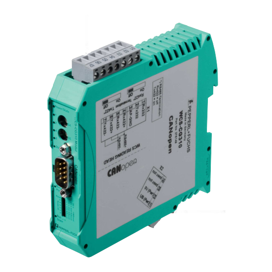
WCS-CG310 Product Description Design of the Device Device Components Figure 2.2 Interface module overview RS-485 terminator sliding switch (behind the terminal block) X1: RS-485 interface Mounting bracket X2: Connection for power supply DIP switch CANopen communication interface CANopen terminator sliding switch... - Page 8 Front panel overview Power: The "Power" LED lights up green: The WCS-CG310 interface module is correctly connected to the power supply. State: The "State" LED lights up green: Data is being exchanged with the WCS reader. The four "Error No/Select ID" LEDs are used to display the number of the currently polled WCS reader.
- Page 9 WCS-CG310 Product Description LED Error No/Select ID Error number Error description LED8 LED4 LED2 LED1 Reserved Hardware error EEPROM error Internal memory error Fieldbus hardware error or incorrect fieldbus ID Script error Reserved Send buffer overflow Receive buffer overflow Timeout when receiving reader data...
- Page 10 S5 = D: cyclically synchronous The WCS-CG310 transmits data after the SYNC command. If one or two WCS readers are connected, PD01 is sent. If more than two WCS readers are connected, PDO1 and PDO2 are sent.
- Page 11 WCS-CG310 Product Description Bus Power: The "Power" LED lights up green: The LED is connected directly to the electrically isolated supply voltage of the CANopen side. CANopen Terminator If the interface module is operated as the first or last physical device in CANopen®, there must be a bus termination on this interface module.
- Page 12 WCS-CG310 Product Description CANopen Fault LED (Red): Fault indicator State Description No error The device is in operational state. Single flash Warning limit has been At least one of the CAN reached controller error counters has reached or exceeded the warning limit (too many error frames).
- Page 13 WCS-CG310 Product Description RS-485 Terminator If the interface module is operated as the first or last physical device in an RS-485 bus, there must be a bus termination on this module. To do this, set the "Rx 422 Termination" slide switch to "Off"...
-
Page 14: Installation
WCS-CG310 Installation Installation Mounting Mounting the Modules The module is fastened to a DIN mounting rail with a width of 35 mm using a snap-on fixing method. Figure 3.1 Mounting 1. Hook the module (1) onto the DIN mounting rail (2) from above and press it down until it snaps into place. -
Page 15: Electrical Connection
WCS-CG310 Installation Electrical Connection Danger! Device damage due to incorrect installation Incorrect installation of cables and connection lines can endanger the function and the electrical safety of the device. Note the permissible core cross section of the conductor. If you are using stranded conductors, crimp the stranded conductors with wire end ferrules. - Page 16 WCS-CG310 Installation Connecting the Power Supply Connect the operating voltage (10 VDC...30 VDC) to terminals 1 and 2 of the 4 pin plug X2 on the interface module. In addition, note the label on the module. The "Power" LED lights up green.
- Page 17 X2-2 Connection to the Control Panel Connect the WCS-CG310 interface module to the CANopen® bus via the 9-pin connector. This requires a 9-pin D-Sub socket that is plugged into the 9-pin D-Sub plug on the device. This socket is not within the scope of delivery for the interface module.
-
Page 18: Dismounting
WCS-CG310 Installation Dismounting Dismounting the modules Use a suitable slot-head screwdriver for dismounting the module. 1. Disconnect all the supply and signal lines. Figure 3.3 Dismounting 2. Insert the screwdriver (2) into the groove of the mounting bracket (3). 3. Press the screwdriver (2) in the specified direction until the lock on the DIN mounting rail (4) opens, see figure. -
Page 19: Operation
Not used Object 0x2000—Polling In polling, a function byte is sent from the master to the WCS-CG310. The WCS-CG310 returns 16 data bytes. The 16 bytes contain the data of the four WCS readers (4 x 4 bytes). If fewer than 4 WCS readers are configured (via rotary switch S4), the 4 data bytes for the WCS readers that are not configured contain the value 0x00. - Page 20 WCS-CG310 Operation Function Number for WCS Reader F0=1 (Send Diagnosis Result) Optical state of OUT Description WCS reader Diagnosis invalid, WCS reader not outside of the code rail Diagnosis result in P16...P18 P16...P18=0 Good P16...P18>0 Poor Error message from WCS reader, error message...
- Page 21 0x00. A WCS reader is not configured if the number of connected WCS readers does not match the number set on the rotary switch S4. The object 1011 h (restore default parameters) is not supported by WCS-CG310. Address Bits A1 and A0...
-
Page 22: Appendix
WCS-CG310 Appendix Appendix Cable Routing in the RS-485 Bus The data cables must always form an in-line connection between the first and the last node. This in-line connection must end with a terminator. The RS-485 terminators are integrated in the WCS readers and can be switched on and off with the interface module. - Page 23 WCS-CG310 Appendix Reading head Reading head Interface or control (PLC) Figure 5.2 Connection of two reading heads, Version A Version B: The interface module is located at the beginning of the data line; one WCS reader is located at the end of the data line. Both need the RS-485 terminator. The second WCS reader is connected to the line connection between the interface module and the first WCS reader through a short spur (length <1 m).
- Page 24 WCS-CG310 Appendix Reading head Spur line (max. 1 m) Reading head Interface or control (PLC) Figure 5.3 Connection of two reading heads, Version B The wiring version used depends on which is best suited for the application. If three or four WCS readers are used on the same interface module, connect these using spurs as shown in variant B.
-
Page 25: Data Cables And Accessories
WCS-CG310 Appendix Data Cables and Accessories RS485 data cable For the RS 485 data transfer path, a 4-wire, shielded, twisted pair data cable must be used. One wire pair is used for the supply voltage, and one pair for the RS 485 data connection. The maximum length of the cable depends on the data transfer capacity of the data cable (core- core) and on the cross section of the cables for power supply of the WCS readers. - Page 26 WCS-CG310 Appendix WCS-DCS / WCS-DCF data cables There are 2 types of data cable available: . WCS-DCS for stationary cable routing . WCS-DCF for trailing cable and drag chain installations. The data cables are twisted pair, and have a tinned copper braided shield. The braided shield surrounds all wire pairs.
- Page 27 Twinsburg, Ohio 44087 · USA Tel. +1 330 4253555 E-mail: sales@us.pepperl-fuchs.com Asia Pacific Headquarters Pepperl+Fuchs Pte Ltd. Company Registration No. 199003130E Singapore 139942 Tel. +65 67799091 E-mail: sales@sg.pepperl-fuchs.com www.pepperl-fuchs.com Subject to modifications / TDOCT5835__ENG Copyright PEPPERL+FUCHS • Printed in Germany 09/2018...