Table of Contents
Advertisement
Quick Links
Advertisement
Chapters
Table of Contents

Related Manuals for Maschio EXTREME 266 Series


Summary of Contents for Maschio EXTREME 266 Series
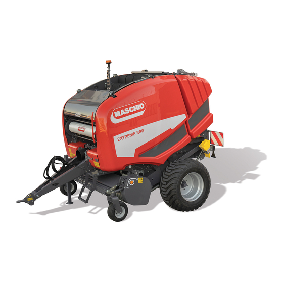
- Page 1 MASCHIO Fienagione S.p.A. EXTREME 266-286 USE AND MAINTENANCE Original manual written in ITALIAN *) Valido per Paesi UE *) Valid for EU member countries *) Valable dans les Pays UE *) Gilt für EU-Mitgliedsländer Cod. F07022408 2020-04 *) Válido para Países UE...
-
Page 3: Table Of Contents
USE AND MAINTENANCE ENGLISH SUMMARY INTRODUCTION ......................2 CERTIFICATION ......................3 TECHNICAL DATA ......................5 GENERAL SAFETY REGULATIONS ................13 SAFETY SIGNS ......................25 SAFETY DEVICES ......................32 TRANSPORT AND HANDLING ..................43 INSTRUCTIONS FOR USE .................... 47 OPERATION IN THE FIELD ..................100 ICON CONTROL SYSTEM .................. -
Page 4: Introduction
Read the operator's manual carefully in its entirety and if you do not understand some points contact your MASCHIO FIENAGIONE dealer or our Assistance Centre, the addresses of which are given on the last page of this manual. -
Page 5: Certification
2004/108/CE Directive (Electromagnetic Compatibility), as shown in the “CE Declaration of Conformity” provided with every machine. MASCHIO FIENAGIONE declines all liability arising from use of the machine on products that do not correspond to European standards. If the machine should be sold to a third party, the declaration of conformity must be handed over together with it. -
Page 6: Road Homologation
ENGLISH USE AND MAINTENANCE ROAD HOMOLOGATION If your round baler is approved for road traffic, the machine will be delivered complete with documents necessary for matriculation. You will then have to go to the office responsible for carrying out the matriculation. Page 4 Cod. -
Page 7: Technical Data
USE AND MAINTENANCE ENGLISH TECHNICAL DATA EXTREME SERIES 266-286 TECHNICAL FEATURES • HTI = with FEEDER • HTR = with ROTOR • HTC = with 13 KNIVES CUT DEVICE • HTU = with 25 KNIVES CUT DEVICE The technical data contained in the following tables are informative therefore we reserve the right to modify them without obligation to give prior notice. -
Page 8: Dimensions
ENGLISH USE AND MAINTENANCE DIMENSIONS 4285 mm 4430 mm LU1 = Machine lenght * (14ft 0.70in) (14ft 6.40in) 4475 mm 4475 mm LU2 = Overall length max. * (14ft 8.18in) (14ft 8.18in) 2500 mm 2500 mm LA MIN = Machine width (with tyres 400/60-15.5) (8ft 2.42in) (8ft 2.42in) 2550 mm... - Page 9 USE AND MAINTENANCE ENGLISH WEIGHTS WITH MODEL 266 Empty weight 266 HTI 266 HTR 266 HTC 266 HTU 3000 kg 3630 kg 3630 kg 3830 kg With tyres 400/60-15.5 (6613lb) (8002lb) (8002lb) (8443lb) 3050 kg 3680 kg 3680 kg 3880 kg With tyres 19.0/45-17 (6724lb) (8113lb)
-
Page 10: Weights With Model 266
ENGLISH USE AND MAINTENANCE WEIGHTS WITH MODEL 286 Empty weight 286 HTI 286 HTR 286 HTC 286 HTU 3050 kg 3680 kg 3680 kg 3880 kg With tyres 400/60-15.5 (6724lb) (8113lb) (8113lb) (8553lb) 3100 kg 3730 kg 3730 kg 3930 kg With tyres 19.0/45-17 (6834lb) (8223lb) -
Page 11: Pick-Up
USE AND MAINTENANCE ENGLISH PICK-UP 220 (L) Max. collection width 2000 mm (6ft 6.74in) Width between tines 1869 mm (6ft 1.58in) Pitch between tines 69 mm (0ft 2.71in) Roll-holder diameter 250 mm (0ft 9.84in) N°. bars for roll-holder N°. tines for bar N°. -
Page 12: Caratteristiche Della Balla
(*) The tractor must be provided with a cabin. If the tractor is not provided with a cabin, you must use special protective sheathing for the hydraulic pipes. MASCHIO FIENAGIONE shall not be held liable for any damage caused due to failure to comply with this warning. -
Page 13: Tyres
USE AND MAINTENANCE ENGLISH TYRES Optional Standard Optional 400/60-15.5 550/45-22.5 19.0/45-17 480/45-17 Ply (P.R.) 875 mm 866mm 1070 mm External diameter (2ft 10.44in) (2ft 10.09in) (3ft 6.12in) 380 mm 380 mm 475 mm Index radius (1ft 2.96in) (1ft 2.96in) (1ft 6.7in) 2745 kg 2860 kg 2975 kg... -
Page 14: Features Of The Control System
ENGLISH USE AND MAINTENANCE FEATURES OF THE CONTROL SYSTEM type ICON Power supply 11÷15 V Dc Controls: membrane keyboard 16+1 keys Display Graphic LCD: 240x64 pixels Back lighting White LEDs Microprocessor 16bit 24Mhz Memories Flash + Static RAM + Eeprom Buzzer Buzzer Degree of protection... -
Page 15: General Safety Regulations
Therefore, read this manual very carefully especially the safety regulations and with great attention to those operations that are potentially very dangerous; if you do this while working it will be too late! MASCHIO FIENAGIONE declines all and any liability for failure to observe the safety and accident prevention regulations provided in this manual. -
Page 16: Safety Warnings
ENGLISH USE AND MAINTENANCE SAFETY WARNINGS Before putting the machine into operation: • Make sure that you have a perfect knowledge of the controls and their functions. • Conduct a regular check of the perfect condition of the entire machine: all the safety and protection devices. •... - Page 17 USE AND MAINTENANCE ENGLISH The area in front of the pick-up is very dangerous; when the machine is in operation, never introduce the forage using the hands, feet or the help of any other object. WARNING! DANGER OF GETTING CAUGHT IN MOVING PARTS OF THE MACHINE. POTENTIAL SERIOUS INJURIES OR DEATH.
- Page 18 Before re-pressurising the system check that the tubes and connections are tight; use a piece of cardboard or absorbent paper to check for possible leaks. MASCHIO FIENAGIONE declines all liability resulting from failure to observe these safety warnings. Page 16...
-
Page 19: Warnings For The Machine
USE AND MAINTENANCE ENGLISH WARNINGS FOR THE MACHINE WARNING! – CAUTION! DANGER OF PRESSURIZED FLUIDS LEAKING. DANGER OF PHYSICAL CONTACT WITH HAZARDOUS SUBSTANCES POTENTIAL SERIOUS INJURIES OR DEATH. The hydraulic couplings shall always be kept clean. To prevent them from becoming dirty or damaged, after use always refit the protective plastic cover provided at the time of purchase. - Page 20 ENGLISH USE AND MAINTENANCE WARNING! – FIRE RISK FIRE HAZARD. POTENTIAL SERIOUS INJURIES OR DEATH. DANGER OF INHALATION OF HAZARDOUS SUBSTANCES. CHOKING HAZARD. Remove the accumulated product regularly to reduce the risk of fire and to prevent material from winding around the mechanical parts of the machine; to do this, always switch off the tractor, remove the key and make sure that all the moving parts have stopped.
-
Page 21: Circulation On The Road
USE AND MAINTENANCE ENGLISH CIRCULATION ON THE ROAD WARNING! LACK OR INADEQUACY OF VISUAL OR ACOUSTIC WARNING DEVICES. POTENTIAL DEATH OR SERIOUS INJURIES FOR THE OPERATOR AND NEARBY PEOPLE. Never drive on public or private roads with a bale in the chamber of the round baler. Always empty the chamber before leaving the field. -
Page 22: Ballast, Wheel Distance And Tyre Inflation Check
If it is necessary to operate in the vicinity of electrical transmission lines contact the competent electricity company. MASCHIO FIENAGIONE declines all liability resulting from failure to observe these safety warnings.. Page 20 Cod. F07022408... -
Page 23: Ecology And Pollution
Improper disposal of waste can threaten the environment and ecological system. The components used for MASCHIO FIENAGIONE equipment which are potentially hazardous waste include: oil, brake fluid and filters. Use airtight containers for drained fluids. -
Page 24: Maintenance In Safety
ENGLISH USE AND MAINTENANCE MAINTENANCE IN SAFETY WARNING! IMPORTANT! POTENTIAL SHEARING OF THE LIMBS. POTENTIAL SERIOUS INJURIES OR DEATH. Before entering the working area of the machine, before performing any adjustment, maintenance or servicing of the machine, and before leaving it unattended, observe the following precautions:: •... - Page 25 Avoid applying high pressure directly on safety labels Immediately re-apply missing safety labels or replace damaged ones. Spare safety labels are available from your MASCHIO FIENAGIONE dealer. Do not wear necktie, scarves, loose clothing, or necklaces when operating the machine or moving parts. Severe injury can be caused if these items get caught in the machine.
- Page 26 Use only the cardan shafts indicated by the manufacturer of the machine This operator manual with instructions for using the round baler must be read memorised and kept for the entire life of the machine. MASCHIO FIENAGIONE declines all liability deriving from failure to observe these warnings. Page 24 Cod. F07022408...
-
Page 27: Safety Signs
USE AND MAINTENANCE ENGLISH SAFETY SIGNS WARNING! LACK OF WARNINGS OF DANGER ON THE MACHINE. POTENTIAL SERIOUS INJURIES OR DEATH. Adhesive signs containing important messages for personal safety are affixed on the machine. Their purpose is to call the operator's attention to safety and health guidelines, as well as to possibly dangerous work and maintenance situations. - Page 28 ENGLISH USE AND MAINTENANCE * only for model HTR, HTC, HTU F20030621 B07500726 * B07500203 B07500203 * B07500221 ** internal B07500203 ** B07500203 B07500221 Page 26 Cod. F07022408...
- Page 29 USE AND MAINTENANCE ENGLISH B07500212 B07500198 B07500198 B07500197 B07500201 F20030621 F20030621 Cod. F07022408 Page 27...
-
Page 30: Pictograms
ENGLISH USE AND MAINTENANCE PICTOGRAMS COD. B07500185 - OPERATOR’S MANUAL WARNING! Before operating the machine, at the beginning of each season and before working on the machine, read and keep in mind the use and maintenance instructions in the operator's manual. -
Page 31: Cod. B07500201 - Electrical Lines
USE AND MAINTENANCE ENGLISH COD. B07500201 - ELECTRICAL LINES WARNING! Take great care when working near electrical lines. COD. B07500203 - MOVING PARTS WARNING! Before performing any work, wait for all parts of the machine to come to a complete stop and prevent any unwanted movement using appropriate equipment. -
Page 32: Cod. B07500724 - Safety Lock
ENGLISH USE AND MAINTENANCE COD. B07500724 - SAFETY LOCK WARNING! Before entering the bale forming chamber to do any operations or for other reasons, lock the hydraulic jacks by turning the valve to the closed position. COD. B07500726 - UPPER LIMBS CUTTING ATTENZIONE! Danger of cutting hands. -
Page 33: Reflectors
USE AND MAINTENANCE ENGLISH REFLECTORS Two types of reflex reflectors are located on the round baler so that it can be seen more clearly during road transpor: R) Round reflectors (front). T) Triangular reflectors (rear). Front Rear Cod. F07022408 Page 31... -
Page 34: Safety Devices
ENGLISH USE AND MAINTENANCE SAFETY DEVICES The machine is provided with safety devices in order to ensure a more correct use without risks in normal working conditions. WARNING! CRUSHING AND SHEARING HAZARD. DANGER OF BLUNT OBJECTS POSSIBLY BEING EJECTED. DANGER OF GETTING CAUGHT IN MOVING PARTS OF THE MACHINE. POTENTIAL DEATH OR SERIOUS INJURIES FOR THE OPERATOR AND NEARBY PEOPLE. - Page 35 USE AND MAINTENANCE ENGLISH The lateral gull-wing door protection guards are provided with a safety lock that ensures perfect closing of the protection guard with the machine and thus prevents accidental opening during work or transport. To open the protection guards a 13mm (0ft 0.51in) spanner is required. WARNING! CRUSHING AND SHEARING HAZARD.
-
Page 36: Tailgate Safety Lock Device
ENGLISH USE AND MAINTENANCE TAILGATE SAFETY LOCK DEVICE There is a safety device to lock the tailgate in the open position thus avoiding accidental closing when the operator is inside the machine for maintenance or repair work. With the tailgate open, turn the lever "L", located on the valve block, in the direction of the red arrow to the stop position (lock closed), as shown in the figure. -
Page 37: Cardan Shaft Support
USE AND MAINTENANCE ENGLISH CARDAN SHAFT SUPPORT This is for the cardan shaft to rest on when it is not connected to the tractor and thus to protect it from damage. SUPPORTS AND CONDUIT GUIDES These support hydraulic tubes, electrical cables and wiring. -
Page 38: Pick-Up Transmission Safety
ENGLISH USE AND MAINTENANCE PICK-UP TRANSMISSION SAFETY The pick-up transmission is provided with a shear bolt torque limiter against overloads and foreign bodies. more information, paragraph “REPLACEMENT PICK-UP SAFETY DEVICE”. BLADES (HTC, HTU) As protection against the entry of foreign bodies into the machine (stones, sticks, etc.) that may cause the blades to break, each blade is mounted on a retractable spring system that allows the blade to lower automatically and then to return automatically to the work position. -
Page 39: Blade Securing Safety Device (Htc, Htu)
USE AND MAINTENANCE ENGLISH BLADE SECURING SAFETY DEVICE (HTC, HTU) The handle “M” secures the blades of the cutting system during operation to prevent them from accidentally entering the bale forming chamber. • Position "1" = blades secured. • Position "2" = blades free. ( 1 ) ( 2 ) From position 1 press the button /... -
Page 40: Devices Against Unauthorised Use
ENGLISH USE AND MAINTENANCE DEVICES AGAINST UNAUTHORISED USE The round baler can be fitted with a device against unauthorised use, to be used at the end of the work shift, during parking or during downtime, to prevent it from being hooked to a tractor and reducing the risk of unauthorised use. -
Page 41: Mechanical Parking Device
USE AND MAINTENANCE ENGLISH MECHANICAL PARKING DEVICE This device allows the machine to be locked and to avoid any accidental movement of the floor during the rest period and whenever it is necessary to block it for repairs, maintenance or cleaning. WARNING! DANGER OF MACHINE FALLING. -
Page 42: Parking Chocks
ENGLISH USE AND MAINTENANCE PARKING CHOCKS If the machine is not equipped with a mechanical parking device, there are parking chocks. The chocks are positioned one on the right side and one on the left side of the round baler. example right side These are place under one tyre under the tyres to block the machine and prevent any accidental... -
Page 43: Brake System To The Tractor
USE AND MAINTENANCE ENGLISH BRAKE SYSTEM TO THE TRACTOR IMPORTANT! In EU countries the braking system is mandatory above 35 quintli per axle. Depending on the model of the round baler and the tracktor to which is connected, there are some variations of the system: •... -
Page 44: Clothing / Ppe
ENGLISH USE AND MAINTENANCE CLOTHING / PPE During work wear suitable clothing. Never wear baggy clothes that flap as these could get caught in the mechanisms and moving parts of the machine. Long hair must be gathered. During maintenance and repairs it is obligatory to use protection gear such as: •... -
Page 45: Transport And Handling
USE AND MAINTENANCE ENGLISH TRANSPORT AND HANDLING WARNING! LOSS OF EQUIPMENT ON THE ROAD AND OF VEHICLE CONTROL, DEATH OR SERIOUS INJURIES FOR THE DRIVER AND THE PEOPLE IN THE VICINITY. LACK OR INADEQUACY OF VISUAL OR ACOUSTIC WARNING DEVICES. POTENTIAL DEATH OR SERIOUS INJURIES FOR THE OPERATOR AND NEARBY PEOPLE. -
Page 46: Loading By Ramp
B07500216. Attach the machine only at the four points indicated by the adhesive signs to avoid damage. MASCHIO FIENAGIONE declines all liability arising from damage to the round baler caused by incorrect attachment for lifting. Page 44... - Page 47 USE AND MAINTENANCE ENGLISH Raise the machine with extreme care and move it slowly, without jerking, onto the lorry or railway car.. WARNING! - CAUTELA! DANGER OF MACHINE FALLING. POTENTIAL SERIOUS INJURIES OR DEATH. Raising and transporting the machine can be very dangerous if not done with the greatest of care, therefore: •...
-
Page 48: Lifting The Machine By Means Of The Car Jack
ENGLISH USE AND MAINTENANCE LIFTING THE MACHINE BY MEANS OF THE CAR JACK When you have to carry out any operation with the wheels raised, you must position the jack in the points indicated on the machine, using the appropriate decal code F20030621. -
Page 49: Instructions For Use
USE AND MAINTENANCE ENGLISH INSTRUCTIONS FOR USE BEFORE USE All operations are to be carried out by a single operator who must have read and understood all the parts of this manual, especially the section on safety. Before starting work, make sure that the machine is in order, that the lubricants are at the right level and that all the parts subject to wear and deterioration are working perfectly. -
Page 50: Assembly Of Drawbar And Towing Eye
POSITION WITH THE BODY UNDER THE ROUND BALER. IMPORTANT! Do the same operation on both left and right sides of the drawbar. MASCHIO FIENAGIONE declines all responsibility for damage attributable to failure to observe these warnings. Page 48 Cod. F07022408... - Page 51 USE AND MAINTENANCE ENGLISH Position the drawbar wings at the two connections on the machine chassis. Push the two M24 screws (one for each drawbar wing) Example left side (outer side) through the holes in the couplings so that the screw head fits properly into the specific hexagonal seat.
- Page 52 ENGLISH USE AND MAINTENANCE IMPORTANT! The towing eye must always be parallel to the ground. The height of the eye from the ground varies according to the adjustment of the drawbar and according to the tyres and the adjustment of the drive shafts at the minimum or maximum height. IMPORTANT! Before tightening the screws, check the correct coupling of the toothed fifth wheels.
-
Page 53: Adjusting The Drawbar / Towing Eye
POSITION WITH THE BODY UNDER THE ROUND BALER. IMPORTANT! Perform the same operation on both the right and left sides of the drawbar. MASCHIO FIENAGIONE declines all responsibility for damage attributable to failure to observe these warnings. Cod. F07022408 Page 51... - Page 54 ENGLISH USE AND MAINTENANCE • Unscrew the screws "V1" that fix the towing eye and the two screws "V2" that fix the wings of the steering bar to the cross-bar of the machine. • Rotate the steering bar to the position for the 'high' hook up of the tractor and, at the same time, keep the towing eye parallel with the ground in the same way.
-
Page 55: Preparing The Tractor
THE TRACTOR CONNECTION BE IN AXIS WITH THE CENTER OF THE JOINT SHAFT PTO. It is allowed a max. Tolerance of "off-axis" between the two axes of ± 50 mm (0ft 1.96in). If it was necessary to use an extension, contact your MASCHIO FIENAGIONE dealer. -
Page 56: Standard Attachment Adjustment
ENGLISH USE AND MAINTENANCE STANDARD ATTACHMENT ADJUSTMENT Machines exit MASCHIO FIENAGIONE with a "STANDARD" tractor connection. Adjust the attachment to the following specifications: • between PTO shaft end and tow-bar attachment pin hole axis A = distance ......... 200 mm (0ft 7.87in) •... -
Page 57: Installing The Control Unit
USE AND MAINTENANCE ENGLISH INSTALLING THE CONTROL UNIT Check that you have the following material contained in the box supplied with the machine: 1) Power cable with fuse "F". 2) “ICON” control terminal 3) Suction pad ( 1 ) ( 2 ) ( 3 ) POSITIONING THE SUCTION PAD Fasten the suction pad stably inside the tractor cab. -
Page 58: Tractor Connection
ENGLISH USE AND MAINTENANCE TRACTOR CONNECTION WARNING! CRUSHING HAZARD. POTENTIAL SERIOUS INJURIES OR DEATH. Take extra care as tractor connection operations can be dangerous. WARNING! LOSS OF EQUIPMENT ON THE ROAD AND OF VEHICLE CONTROL, DEATH OR SERIOUS INJURIES FOR THE DRIVER AND THE PEOPLE IN THE VICINITY. - Page 59 USE AND MAINTENANCE ENGLISH Hook the baler to the rear hook of the tractor, making sure that the machine is in a stable and horizontal position and that the towing eye is at the same height as the tractor towing device. •...
- Page 60 ENGLISH USE AND MAINTENANCE If the machine is equipped with a safety chain A, hook and fasten the chain (A) to the tractor. Allow only enough slack for turns. • Make sure that the hatch and all covers are properly closed and hooked. •...
-
Page 61: Connection Of Various Devices Of The Round Baler
USE AND MAINTENANCE ENGLISH CONNECTION OF VARIOUS DEVICES OF THE ROUND BALER After completing the hooking up of the round baler to the towing device of the tractor “TRACTOR CONNECTION”, continue with the connection of the various devices of the round bale: •... -
Page 62: Installing And Connecting Baler Wiring To The Icon Control Terminal
ENGLISH USE AND MAINTENANCE INSTALLING AND CONNECTING BALER WIRING TO THE ICON CONTROL TERMINAL IMPORTANT! Make sure that no cables are a hindrance to driving maneuvers and are not near moving parts. Make sure that the tractor power cable, once connected to the machine cable, does not hit against the PTO and does not interfere with working operations. -
Page 63: Connecting The Seven-Contact Outlet For Towing
For any maintenance and / or repairs, contact our Customer Service. MASCHIO FIENAGIONE declines any responsible for any consequences of failure to heed warnings. CONNECTION TO THE HYDRAULIC SYSTEM OF THE TRACTOR WARNING! DANGER OF PHYSICAL CONTACT WITH HAZARDOUS SUBSTANCES DANGER OF PRESSURIZED FLUIDS LEAKING. -
Page 64: Flexible Hydraulic Hoses
ENGLISH USE AND MAINTENANCE FLEXIBLE HYDRAULIC HOSES IMPORTANT! Check conditions of hydraulic hoses at the beginning of each season. If conditions are not optimum, check more frequently. Due to the ageing of rubber, it is advisable to replace the hydraulic hoses every 5 years. WARNING! DANGER OF PHYSICAL CONTACT WITH HAZARDOUS SUBSTANCES DANGER OF PRESSURIZED FLUIDS LEAKING. -
Page 65: Connecting Flexible Hydraulic Hoses For Lifting The Collector And Hatch
USE AND MAINTENANCE ENGLISH CONNECTING FLEXIBLE HYDRAULIC HOSES FOR LIFTING THE COLLECTOR AND HATCH • Using force, insert the ends of the hoses in the tractor attachments. • To move the hatch and the cut group, connect the flexible hydraulic hoses (A) to a double acting hydraulic distributor. •... -
Page 66: Connecting The Telescopic Shaft To The Pto Shaft Of The Tractor
ENGLISH USE AND MAINTENANCE CONNECTING THE TELESCOPIC SHAFT TO THE PTO SHAFT OF THE TRACTOR WARNING! DANGER OF GETTING CAUGHT IN THE CARDAN SHAFT. POTENTIAL SERIOUS INJURIES OR DEATH. The cardan shaft is a transmission component (machine), equipped with a "CE" certificate. Each cardan shaft is equipped with a use and maintenance manual. - Page 67 After all maintenance operations performed on the cardan shaft, always reset protective caps on the shaft itself. During baler operations, replace the cardan shaft support along the steering head side. MASCHIO FIENAGIONE declines any responsible for any consequences of failure to heed warnings. Cod. F07022408 Page 65...
-
Page 68: Check The Steering Angle
CARDAN SHAFT DECAL There is a sticker on the cardan shaft which requests the operator complies with safety standards for shaft use. MASCHIO FIENAGIONE declines any responsible for any consequences of failure to heed warnings. Page 66 Cod. F07022408... -
Page 69: Connecting The Brake System To The Tractor
USE AND MAINTENANCE ENGLISH CONNECTING THE BRAKE SYSTEM TO THE TRACTOR WARNING! CRUSHING HAZARD. POTENTIAL SERIOUS INJURIES AND DEATH. The operation must be performed on a horizontal plane. Always connect the braking system to the tractor with: the tractor switched off, the keys removed from the dashboard and all the moving parts of the machine are completely stopped To avoid accidents caused by unexpected movements, firmly place the machine on firm, flat and horizontal ground, and blocked it by operating the mechanical parking device. - Page 70 ENGLISH USE AND MAINTENANCE Connection of the joint to the line «SL» Rotate the joint so as to align the SL attachment in correspondence with that of the tractor. Push the joint forward to complete the atachment. IMPORTANT! Do not connect the double hydraulic line brake system to tractors that do not comply with the provisions of 167/2013/EU.
-
Page 71: Reconnecting To The Tractor
USE AND MAINTENANCE ENGLISH RECONNECTING TO THE TRACTOR Once taht the double line joint is reconnected to the tractor, the engine is started and the tractor parking brake is removed, following the increase of the pressure in the SL line, the selector automatically returns to the normal operating position “0”. -
Page 72: Emergency Brake
ENGLISH USE AND MAINTENANCE EMERGENCY BRAKE The hydraulic braking system is equipped with an emergency brake which in cases of: accidental detachment of the equipment from the tractor, detachment of the electrical connection from the towing vehicle, detachment of the coupling joint, power failure in the electrical connection, the pressure in the supplementary line drops below 12 bar (174.12 psi), it generates the automatic activation of the brakes using the energy stored inside the hydraulic accumulator. -
Page 73: Connecting Of The Air Braking System
USE AND MAINTENANCE ENGLISH CONNECTING OF THE AIR BRAKING SYSTEM Connect the air circuit connexion to the tractor outlet. Connexion ISO Connexion CUNA (only for ITALY) With the machine stopped, by disconnecting the air connexion from the tractor socket, the hydro-pneumatic braking device locks the hubs of the baler wheels. -
Page 74: Running In Of The Brakes
ENGLISH USE AND MAINTENANCE RUNNING IN OF THE BRAKES This is required so as to obtain the best braking efficiency. IMPORTANT! The running in must be carried out with the round baler at full load. 1st phase - Adaptation: Perform approximately 20 brakes (cold) with an average force on the levers (about 8-10% of the total load on the axles). -
Page 75: Disconnection
USE AND MAINTENANCE ENGLISH DISCONNECTION DISCONNECTING THE CARDAN SHAFT FROM THE PTO SHAFT OF THE TRACTOR IMPORTANT! Before disconnecting the PTO shaft: Disengage the PTO, engage the parking brake, stop the engine and remove the ignition key. To disconnect the telescopic shaft properly from the PTO shaft, refer to the telescopic shaft operator's manual. -
Page 76: Disconnecting The Brake System To The Tractor
ENGLISH USE AND MAINTENANCE DISCONNECTING THE BRAKE SYSTEM TO THE TRACTOR WARNING! CRUSHING HAZARD. POTENTIAL SERIOUS INJURIES AND DEATH. The operation must be performed on a horizontal plane. Always connect the braking system to the tractor with: the tractor switched off, the keys removed from the dashboard and all the moving parts of the machine are completely stopped To avoid accidents caused by unexpected movements, firmly place the machine on firm, flat and horizontal ground, and blocked it by operating the mechanical parking device. -
Page 77: Disonnecting Of The Hydraulic Braking System
USE AND MAINTENANCE ENGLISH DISONNECTING OF THE HYDRAULIC BRAKING SYSTEM With both hands grab the release flange. Move it backwards until it reaches the end of the stroke so as to release the joint, keeping it in this position, move the joint away from the tractor attachments. IMPORTANT! In this condition, to avoid the accumulation of dirt on the coupling joint, it is possible to store and lock the coupling... -
Page 78: Disonnecting Of The Air Braking System
ENGLISH USE AND MAINTENANCE DISONNECTING OF THE AIR BRAKING SYSTEM Disonnect the air circuit connexion from the tractor outlet. In this case the round baler will block due to the pressure exerted on the wheel hubs. To unlock the hubs of the round baler wheels without connecting the air circuit connexions to the tractor outlet, press the release button. -
Page 79: Disconnecting From The Tractor
USE AND MAINTENANCE ENGLISH DISCONNECTING FROM THE TRACTOR Before disconnecting the baler from the tractor: • Move crank "M" to lower the servo steering head to the ground. • Remove cotter "S" from the towing eye and move the tractor away from the machine. Cod. -
Page 80: Prove Di Funzionamento
ENGLISH USE AND MAINTENANCE PROVE DI FUNZIONAMENTO CAUTION! CRUSHING HAZARD. POTENTIAL SERIOUS INJURIES OR DEATH. The round baler is always attached to the tractor before any operation, whether empty or containing a bale. SELECTING THE TRACTOR PTO REGIME IMPORTANT! NEVER insert the PTO before starting the tractor motor. To select the tractor PTO regime, refer to the label on the front of the baler. -
Page 81: Setting The Machine Up For Work
USE AND MAINTENANCE ENGLISH SETTING THE MACHINE UP FOR WORK Before starting work make all the necessary adjustments to prepare the machine for your specific work requirements. TWINE SELECTION For the twine binder to work well we advise using propylene twine with a yarn count from 500 to 750 or 1000 (m/kg). - Page 82 ENGLISH USE AND MAINTENANCE • Open the right side guard and place the spools of twine in the special box. • Connect the six spools, one to the other, in two groups of three (1+2+3 and 4+5+6), passing the twine through the slots of the separators.
- Page 83 ENGLISH USE AND MAINTENANCE • Thread the twine through the eyes "O". • Through the two bushings "B" and the two twine braking devices "F2" located on the arm of the binder; then pass it through the two tubes so that it protrudes from the other end by about 20cm (0ft 7.87in), as shown in the figure (use one twine per path).
-
Page 84: Twine Adjustment
ENGLISH USE AND MAINTENANCE TWINE ADJUSTMENT The “ICON” control system allows you to control the parameters with which to set the double twine tying, independently of the value of the bale diameter: • “A” = distance of the twine from the head of the bale. •... -
Page 85: Twine Braking Device Adjustment
USE AND MAINTENANCE ENGLISH TWINE BRAKING DEVICE ADJUSTMENT There are some twine braking devices on the round baler to adjust the tension of the twine: • “F1” located on the twine spool box, • “F2” located on the arm of the binder. ( F1 ) ( F1 ) ( F2 ) -
Page 86: Twine Cutter Blade Extension
ENGLISH USE AND MAINTENANCE TWINE CUTTER BLADE EXTENSION If it is necessary to tie a great deal inside the edge of the bale (twine cutter side) it may be necessary to adjust the blade arm by extending the small blade: •... -
Page 87: Selecting The Net Roll
USE AND MAINTENANCE ENGLISH SELECTING THE NET ROLL The baler is equipped for use with standard type reels. For best performance, use 14÷16 g/m net rolls. The round baler can use spools from 2000 to 4200 metres (from 6561ft 8.15in to 13ft 9.35in). IMPORTANT! Higher density net rolls can be used. -
Page 88: Loading The Net Binder
ENGLISH USE AND MAINTENANCE LOADING THE NET BINDER WARNING! DANGER OF GETTING CAUGHT IN MOVING PARTS OF THE MACHINE. POTENTIAL CRUSHING OR SHEARING OF THE LIMBS. POTENTIAL SERIOUS INJURIES OR DEATH. Before installing the net binder: • disconnect the PTO, •... - Page 89 USE AND MAINTENANCE ENGLISH The “ICON” control system needs to be turned on to move the binder arm in order to perform some of the operations described below. Further information on turning on the “ICON” control system can be found in the chapter: “ICON CONTROL SYSTEM / SYSTEM DESCRIPTION”.
- Page 90 ENGLISH USE AND MAINTENANCE Bring the net wrapper arm to an intermediate position so as to be able to insert the net into the grip. • Unhook the two safety hooks "G" (one on the right and one on the left) and raise the entire box for the net.
- Page 91 USE AND MAINTENANCE ENGLISH IMPORTANT! Take great care to push the net roll onto the tube correctly so that it rotates in the right direction as shown on the decal. NOTE: On the binder arms there are decals showing the right path of the net.
-
Page 92: Net Binder Adjustment
ENGLISH USE AND MAINTENANCE NET BINDER ADJUSTMENT The “ICON” control system allows you to set the number of revolutions to be used to wrap the bale. Further information on modifying the net parameters can be found in the chapter: “ICON CONTROL SYSTEM / MENU / PROGRAM / PROGRAM SETTINGS”. -
Page 93: Replacing The Blade Of The Net Binder
USE AND MAINTENANCE ENGLISH REPLACING THE BLADE OF THE NET BINDER CAUTION! POTENTIAL CRUSHING OR SHEARING OF THE LIMBS. POTENTIAL SERIOUS INJURIES OR DEATH. Take great care regarding the blade sections. If the wrapper blade sections do not cut the net (the blades are worn or broken) they must be replaced: •... -
Page 94: Adjustment Of The Pick-Up Wheels
ENGLISH USE AND MAINTENANCE ADJUSTMENT OF THE PICK-UP WHEELS It is possible to adjust the working height of the pick-up: o raise or lower the height of the pick-up change the position of the pin "S", located on the support wheel arm, by inserting it into one of the holes located on the side of the pick-up to give the working height required. -
Page 95: Rake (Hti)
USE AND MAINTENANCE ENGLISH RAKE (HTI) Depending on the type of swathe to be collected the rake can be moved to a number of positions: • Low: for swathes of low volume • Medium: for voluminous swathes • High: for very voluminous swathes WARNING! DANGER OF GETTING CAUGHT IN MOVING PARTS OF THE MACHINE. -
Page 96: Feeder Plate (Htr, Htc, Htu)
ENGLISH USE AND MAINTENANCE FEEDER PLATE (HTR, HTC, HTU) In the machines with a rotor, a feeder plate optimises the collection and channelling of the product into the baler. The distance of the plate from the tines of the pick-up can be adjusted by moving the blocks “T”. WARNING! DANGER OF GETTING CAUGHT IN MOVING PARTS OF THE MACHINE. - Page 97 USE AND MAINTENANCE ENGLISH ( example on the left side ) • Loosen the screw "V" that secures the block "T", and position it in one of the holes located on the side of the pick-up to suit the work to be done; then screw back the screws “V”.
-
Page 98: Cutter System (Htc, Htu)
ENGLISH USE AND MAINTENANCE CUTTER SYSTEM (HTC, HTU) If your machine is provided with a cutter system, 13 knives (HTC) or 25 knives (HTU), you will have the option of cutting the product while picking up the swathes. Using the control terminal “ICON”, the knives must be engaged in the chamber in order to be able to cut. More information relative to the engagement or disengagement of the knives can be found in the chapter: “ICON CONTROL SYSTEM / MENU / MANUAL MODE / CUT”. -
Page 99: Bale Diameter Selection
USE AND MAINTENANCE ENGLISH BALE DIAMETER SELECTION Using the terminal of the “ICON” control system you can select the diameter with which you intend to work. Depending on your round baler model you can obtain bales with diameters that vary from a minimum of 0.50m (1ft 7.68in) to a maximum of: •... -
Page 100: Preparazione Del Campo
ENGLISH USE AND MAINTENANCE PREPARAZIONE DEL CAMPO IMPORTANT! All operations should be performed by a single operator who must have read and understood all parts of this manual, particularly the chapters regarding safety. To ensure the maximum efficiency during collection and baling of the various products we advise operating as described below: CONDITIONING It is important for the forage to be conditioned to ensure uniform humidity content in stems and leaves. -
Page 101: Short, Dry, Smooth Product Bales
USE AND MAINTENANCE ENGLISH SHORT, DRY, SMOOTH PRODUCT BALES In case of obstruction, attempt one of the following: • Lift the collector to maximum. • Reduce tractor PTO regime. • Reduce the density of bales when necessary. • Make wider swaths (add as needed). •... -
Page 102: Operation In The Field
ENGLISH USE AND MAINTENANCE OPERATION IN THE FIELD SWITCHING ON After you have set up the machine as described in the chapter “INSTRUCTIONS FOR USE”, switch on the “ICON” control system in order to start work NOTE: Prima di iniziare il lavoro potrete, attraverso il terminale, rivedere e/o modificare i valori del programma con cui la vostra macchina è... -
Page 103: Feed Speed
USE AND MAINTENANCE ENGLISH FEED SPEED The feed speed depends on the type of product to be baled and the ground contours. LOADING (OPTIONAL KIT) If your round baler is provided with the loading indicator kit, and the function has been activated, you can monitor the product loading inside the chamber. -
Page 104: Binding
ENGLISH USE AND MAINTENANCE BINDING When you have reached 90% of the bale diametr, the “ICON” control system, by using an intermittent acoustic signal, warns you that you are about to reach the bale rated pressure value set in the program. Once this value is obtained, another continuous acoustic signal warns you that you must immediately stop the movement of the tractor so that the binding machine can bind the bale. -
Page 105: Unloading Bale
USE AND MAINTENANCE ENGLISH UNLOADING BALE At the end of each binding cycle, the net and / or the wire are cut and the ICON control system will prompt you to open the hatch to unload the bale on the ground. WARNING! IMPACT HAZARD. -
Page 106: Unblockage Of The Product
ENGLISH USE AND MAINTENANCE UNBLOCKAGE OF THE PRODUCT WARNING! DANGER OF GETTING CAUGHT IN MOVING PARTS OF THE MACHINE. POTENTIAL SERIOUS INJURIES OR DEATH. If the round baler should block up with product while working, do not try to remove the product from the machine while it is in operation. -
Page 107: Clearing The Pick-Up (Htr, Htc, Htu)
USE AND MAINTENANCE ENGLISH CLEARING THE PICK-UP (HTR, HTC, HTU) The product is jammed between the collection channel plate and the tines of the pick-up. CAUTION! IMPACT HAZARD. CRUSHING HAZARD. POTENTIAL SERIOUS INJURIES OR DEATH. • Remove the collection channel plate (as indicated in the paragraph: “FEEDER PLATE”). •... -
Page 108: Clearing The Rotor E (Htr, Htc, Htu)
ENGLISH USE AND MAINTENANCE CLEARING THE ROTOR E (HTR, HTC, HTU) An excessive volume of the product is blocked between the rotor and the collection channel. The automatic baler has a device to avoid clogging of the product during the product feeding phase. If an excessive amount of product clogs the feeding channel, the PTO shaft overload clutch will automatically disengage and make a clearly audible noise. -
Page 109: Stopping The Machine
USE AND MAINTENANCE ENGLISH STOPPING THE MACHINE IMPORTANT! On finishing work the operator must: • Stop the machine. • Make sure that all the moving parts of the machine have stopped and are in the rest position. • Stop the tractor motor and remove the keys from the dashboard. •... -
Page 110: Icon Control System
ENGLISH USE AND MAINTENANCE ICON CONTROL SYSTEM GENERAL WARNINGS • Read carefully this manual before using the weight indicator • Be sure that the electrical power supply is as per system requirements (12 V DC) • Do not push on the display as this may cause some afterimages •... -
Page 111: System Description
USE AND MAINTENANCE ENGLISH SYSTEM DESCRIPTION 1) DISPLAY 2) ON/OFF KEY 3) OPERATING KEYS 4) CONNECTOR MAIN FUNCTIONS BEFORE STARTING Check that the power supply - communication cable is connected to the Indicato. SWITCHING ON AND OFF To switch on the system press shortly the On / Off Key The Indicator display will light on, while the initializing messages and the presentation are displayed. -
Page 112: Function Description - Working Screen
ENGLISH USE AND MAINTENANCE FUNCTION DESCRIPTION – WORKING SCREEN The working screen contains visualizations and commands which allow the operator to perform product collection, bale tying and eject. 1) OPERATING PHASE INFORMATION 2) DESCRIPTIONS 3) CUT STATUS 4) AUTO/MANUAL TYING 5) START TYING 6) OTHER KEYS 7) MENU... - Page 113 USE AND MAINTENANCE ENGLISH Visualizations during collecting phase (hard core bale): • FORMING BALE PRESSURE. • PTO SPEED (364 RPM in example above). Once the forming bale has reached the minimum size of the room, the above screen is replaced by the following, in which also appear the following information i: •...
- Page 114 ENGLISH USE AND MAINTENANCE Visualizations during collecting phase (pre-chamber core bale): • PTO SPEED (364 RPM in example above). • SIDE BARS OF LOADING CHAMBER SENSORS: show to the operator the machine side that has to be loaded more to maintain uniform pressure in the bale;...
- Page 115 USE AND MAINTENANCE ENGLISH NOTICE: if the door is accidentally opened during collecting phase, both a sound and a visual indication start, to show to the operator that he must close it. NOTICE: if the tape is accidentally opened during collecting phase, both a sound and a visual indication start, to show to the operator that he must close it.
- Page 116 ENGLISH USE AND MAINTENANCE Views during the NET binding phase: • NUMBER OF NET TURNS BEING DONE. • METERS OF USED NET. During this phase, the operator can also decide to stop the tying cycle, by pressing the key near to the icon This will lead to a message of cycle interruption due to a tying error, with a few available choices to proceed with the cycle: Enter manual mode in the section about the tyring type in use, to perform manual...
- Page 117 USE AND MAINTENANCE ENGLISH Views during the TWINE binding phase: • TURNS OF WIRE THAT THE BINDING MAKES ON THE RIGHT HEAD OF THE BALE; • TURNS OF WIRE THAT THE BINDING MAKES ON THE CENTRAL COILS OF THE BALE; •...
- Page 118 ENGLISH USE AND MAINTENANCE During the tying may happen that the twine runs out. First the screen that appears will be this, showing two triangles with an exclamation mark. This will lead to an tying error message due to lack of binding twine, with a few available choices to proceed with the cycle: •...
- Page 119 USE AND MAINTENANCE ENGLISH Views during the DOUBLE TWINE-NET binding phase: The display shows all the data, readable by the operator, based on the configuration of the machine: • TURNS OF WIRE THAT THE BINDING MAKES (STARTING FROM ZERO UNTIL THE VALUE SET IN THE PROGRAM); •...
- Page 120 ENGLISH USE AND MAINTENANCE Visualizations during open request phase (Open): • MACHINE STATUS (CLOSED GATE). • THE OPERATOR IS REQUIRED TO OPEN THE GATE, USING THE HYDRAULIC COMMAND LEVER ONBOARD THE TRACTOR; During this phase, the operator can also decide to press the key near to the icon , avoiding the gate sensor signal, which indicates that the gate is closed, and go to the next phase or even repeat the tying phase, by pressing the key near to the icon.
-
Page 121: Descriptions
USE AND MAINTENANCE ENGLISH 2) DESCRIPTIONS Measures and counters regarding the actual work, displayed on different sections: SECTION 1 SECTION 2 SECTION 3 SECTION 4 SECTION 5 SECTION 6 For double binding, they are displayed first one and after the other. SECTION 1 •... - Page 122 ENGLISH USE AND MAINTENANCE SECTION 3 NOTE: The display will be different depending on the type of binding used: NET: • TYING TURNS FOR THE ACTIVE PROGRAM • REMAINING NET LENGTH TWINE • NUMBER OF WIRE TURNS AT THE CENTER OF THE BALE •...
-
Page 123: Cut Status
USE AND MAINTENANCE ENGLISH 3) CUT STATUS VISUALIZATIONS The icon displays the status of the cut groups: = CUT: cut groups outside the chamber;; = CUT ON: cut group inside the chamber. COMMANDS Pressing the side key near to this icon, you can access the “CUT MANAGEMENT” page in the “MANUAL MODE” menu, where it’s possible to manage the cut group. -
Page 124: Other Keys
ENGLISH USE AND MAINTENANCE 6) OTHER KEYS COMMANDS Press the key below this icon to access other keys or information needed on the displayed screen (if present). In addition to the functions of the buttons described above, there are the following commands: Pressing the side key next to the icon road lights are turned on / off;... -
Page 125: Main Menu
USE AND MAINTENANCE ENGLISH MAIN MENU The main menu is made of some icons which leads to other menus, described by the icons in below image. 1) WORKING SETTINGS 2) PROGRAM 3) SYSTEM INFORMATION 4) COUNTERS 5) SYSTEM EVENTS 6) MANUAL MODE 7) GREASING 8) ADVANCED SETTINGS 9) BACK TO WORKING SCREEN... -
Page 126: Working Settings
ENGLISH USE AND MAINTENANCE WORKING SETTINGS VISUALIZATIONS (page 1) • SIMULATE PTO: selection of PTO speed simulation (Yes / No); • EXCLUDE HOOKS: selection of the hatch’s closing hooks exclusion (Yes / No); • EXCLUDE DIAMETER: selection of the bale diameter view exclusion (Yes / No);... - Page 127 USE AND MAINTENANCE ENGLISH VISUALIZATIONS (page 2) • STRING REELS: allows the control of the wire rolls to be excluded (YES/NO) The active control allows the wire to the correctly attached to the bale. With the active control of the rolls, the arm of the wire binder enters the chamber and stops on the first bale head.
-
Page 128: Program
ENGLISH USE AND MAINTENANCE PROGRAM VISUALIZATIONS • PROGRAM NUMBER (from 1 to 10); • PROGRAM NAME; • PROGRAM MAIN SETTINGS: • BALE DIAMETER; • BALE CORE SETTINGS (80 cm pre-chamber diameter in the example) • TYING PRESSURE; (from 90 to 105 BAR from pre-chamber end and bark start) •... -
Page 129: Program Statistics
USE AND MAINTENANCE ENGLISH PROGRAM STATISTICS VISUALIZATIONS • PROGRAM NAME; • WORK TIME: working hours of the machine (since the last zeroing) • BALE COUNTER: number of bales made with the selected program (since last statistics zeroing); • NET USED: meters of net used with the selected program (since last statistics zeroing);... -
Page 130: Program Settings
ENGLISH USE AND MAINTENANCE PROGRAM SETTINGS VISUALIZATIONS (page 1) • PROGRAM NAME: name of the selected program; • DIAMETER; • CORE: • HARD: bale core is formed with initial pression set; • PRE-CHAMBER: bale core is formed without pressing the material, until reaching the core diameter;... - Page 131 USE AND MAINTENANCE ENGLISH Press the side keys near to the icons , to access to a screen where the value of a parameter can be edited: In the case of the DIAMETER parameter, for instance, pressing the side keys near to the icons , the parameter value can be modified in the range from 70 to 165 cm.
- Page 132 ENGLISH USE AND MAINTENANCE VISUALIZATIONS (page 2) • INITIAL PRESSURE: initial pressure to form the bale, after core formation. During bale creation this value varies linearly until reaching the final pressure described below; • FINAL PRESSURE: final pressure of bale formation. During the creation of the bale, the pressure varies from the value of the initial pressure as described above until reaching the final pressure when the bale is completed;...
- Page 133 USE AND MAINTENANCE ENGLISH VISUALIZATIONS (page 3) NOTE: The binding items is represented by a single screen, regardless of the type of binding set. • BINDER: binder type used by the selected program: • NET: bale is tied with net binder; Parameters shown only with NET binding: •...
- Page 134 ENGLISH USE AND MAINTENANCE In the case of the parameter EDGE DISTANCES, pressing the side buttons next to the icons and , it is possible to vary the value of the parameter, in the indicated range, from 8 to 28 cm. The parameter value can be confirmed by pressing the key below the icon simply waiting: after 5 seconds, the system goes back to previous screen.
-
Page 135: System Information
USE AND MAINTENANCE ENGLISH SYSTEM INFORMATION VISUALIZATIONS (page 1): • FIRMWARE: name, code and date of the firmware version installed on the system; • CHECKSUM: unique code linked to the installed firmware; • FREE MEMORY: memory records available; • USED MEMORY: memory records used; •... - Page 136 ENGLISH USE AND MAINTENANCE VISUALIZATIONS (page 3-5): • MACHINE MAIN FEATURES: values of the parameters of the machine • PAGE NO. / TOTAL PAGES; COMMANDS (page 3) • Press the side key near to the icon to access the previous page; •...
- Page 137 USE AND MAINTENANCE ENGLISH VISUALIZATIONS (page 7) Information about the modules installed on the machine and firmware version. The code on a black background in the left column indicates the installed device, if the device communicates with the bus, in the right column displays the firmware version of the module itself.
-
Page 138: Counters
ENGLISH USE AND MAINTENANCE COUNTERS VISUALIZATIONS NOTE: the voice of the tying machine counter is represented by a single screen, regardless of the type of tying set. • COUNTER IN USE (from 1 to 10); • COUNTER NAME; • TOTAL: total number of bales made with selected counter; •... -
Page 139: Global Counter
USE AND MAINTENANCE ENGLISH GLOBAL COUNTER VISUALIZATIONS NOTE: the voice of the tying machine counter is represented by a single screen, regardless of the type of tying set: • GLOBAL COUNTER; • TOTAL: total number of bales made; • NET: total number of bales made with the net tying unit; •... -
Page 140: Counter Settings
ENGLISH USE AND MAINTENANCE COUNTER SETTINGS VISUALIZATIONS • COUNTER NAME: name of the selected program COMMANDS Press side keys next to the symbol that represents the menu to see the name of the menu for about 2 seconds. Press the side key near to the icon to access a screen where character strings can be inserted: In the case of the parameter PROGRAM NAME, for instance, pressing the side keys... -
Page 141: System Events
USE AND MAINTENANCE ENGLISH SYSTEM EVENTS VISUALIZATIONS (page 1) • DESCRIPTION OF LAST 5 EVENTS; • PAGE NO. / TOTAL PAGES; COMMANDS (page 1) Press side keys next to the symbol that represents the menu to see the name of the menu for about 2 seconds. -
Page 142: Manual Mode
ENGLISH USE AND MAINTENANCE MANUAL MODE VISUALIZATIONS (page 1) • Activates the net stop sensor; • Activates the net roll impulse sensor and the relative counter; • TYING UNIT MOTOR CONSUMPTION: current absorption, in A. • PAGE NO. / TOTAL PAGES; COMMANDS (page 1) Press side keys next to the symbol that represents the menu to see the name of the menu for about 2 seconds. - Page 143 USE AND MAINTENANCE ENGLISH VISUALIZATIONS (page 2) • Indication of the position of the linear electric actuator that manages the wire, expressed in cm; • TYING UNIT ACTUATOR CONSUMPTION: current absorption, in A. • PAGE NO. / TOTAL PAGES; COMMANDS (page 2) •...
- Page 144 ENGLISH USE AND MAINTENANCE VISUALIZATIONS (page 3) • CUT GROUP STATUS: the view vary from CUT OFF (cut group not in chamber) to CUT ACTIVATED (cut group in chamber); • I1: hydraulic system pressure, indicator #1; • I2: hydraulic system pressure, indicator #2; •...
- Page 145 USE AND MAINTENANCE ENGLISH VISUALIZATIONS (page 4) • TAPE STATUS: the view vary from OPENED TAPE to CLOSED TAPE; • I3 (FC for machines without cut group): opened tape sensor; • I1: hydraulic system pressure, indicator #1; • I2: hydraulic system pressure, indicator #2; •...
-
Page 146: Greasing
ENGLISH USE AND MAINTENANCE GREASING VISUALIZATIONS • BALES NUMBER: number of bales after which a greasing cycle will automatically start (based on settings in section 1); • HOURS NUMBER: number of hours after which a greasing cycle will automatically start (based on settings in section 1); •... -
Page 147: Advanced Settings
USE AND MAINTENANCE ENGLISH ADVANCED SETTINGS 1) Clock 2) Diagnostic 3) Interface options 4) Alarms management 5) USB management 6) Reserved area 7) Back to main menu Press the keys near to the icons to access to menus. Cod. F07022408 Page 145... -
Page 148: Advanced Option - Clock
ENGLISH USE AND MAINTENANCE ADVANCED OPTION - CLOCK VISUALIZATIONS (page 1) • HOURS; • MINUTES; • AUTOMATIC DAYLIGHT SAVING TIME UPDATE: automatic update to Daylight Saving Time; • PAGE NO. / TOTAL PAGES. COMMANDS (page 1) Press side keys next to the symbol that represents the menu to see the name of the menu for about 2 seconds; Press the side keys near to the icons , to access to a screen where the value of a parameter can be edited::... - Page 149 USE AND MAINTENANCE ENGLISH VISUALIZATIONS (page 2) • DAY: day of the week; • DAY: day of the month; • MONTH; • YEAR; • PAGE NO. / TOTAL PAGES. COMMANDS (page 2) Press side keys next to the symbol that represents the menu to see the name of the menu for about 2 seconds; Press the side keys near to the icons , to access to a screen where the value of a parameter can be edited:...
-
Page 150: Advanced Option - Diagnostic
ENGLISH USE AND MAINTENANCE ADVANCED OPTION – DIAGNOSTIC Access and use of Diagnostic menu functions are reserved to skilled staff only who has received appropriate training about the machine. To perform some operations, a password may be requested. In order to uniquely identify the functions, some terms have been inserted only in English, to avoid any ambiguity related to the translation into the various language. - Page 151 USE AND MAINTENANCE ENGLISH VISUALIZATIONS (page 2) • Indication of the position of the linear electric actuator that manages the wire, expressed in cm; • TYING UNIT ACTUATOR CONSUMPTION: current absorption, in A. • PAGE NO. / TOTAL PAGES; COMMANDS (page 2) Press side keys next to the symbol that represents the menu to see the name of the menu for about 2 seconds.
- Page 152 ENGLISH USE AND MAINTENANCE VISUALIZATIONS (page 3) • CUT GROUP STATE: view vary from CUT OFF (cut group not in chamber) to CUT ACTIVATED (cut group in chamber); • TAPE STATE: view vary from OPENED TAPE to CLOSED TAPE; • I3 (FC for machines without cut group): tape opened sensor;...
- Page 153 USE AND MAINTENANCE ENGLISH VISUALIZATIONS (page 4) • Current set in the variable geometry circuit, proportional to the pressure set; • Ammeter check in the variable geometry circuit; • Pressure sensor check in P1 chamber; • Variable Geometry icon, with or without black frame, , depending on whether the function is active or not;...
- Page 154 ENGLISH USE AND MAINTENANCE VISUALIZATIONS (page 5) • Forming bale diameter value (cm); • Direct check of the diameter sensor; • PAGE NO. / TOTAL PAGES; COMMANDS (page 5) Press side keys next to the symbol that represents the menu to see the name of the menu for about 2 seconds. Press the side key near to the icon to activate the wizard to run the maximum diameter self-learning procedure.
- Page 155 USE AND MAINTENANCE ENGLISH VISUALIZATIONS (page 6) • Values measured by right and left load potentiometers; • Percentage of right and left load; • PAGE NO. / TOTAL PAGES; COMMANDS (page 6) Press side keys next to the symbol that represents the menu to see the name of the menu for about 2 seconds. Press the side key near to the icon , to activate the wizard to run the self-learning procedure of maximum and minimum positions of load sensors.
- Page 156 ENGLISH USE AND MAINTENANCE VISUALIZATIONS (page 7) INSTALLED SENSOR STATE VIEW. In the example screen on the right: • DI: bale diameter sensor; • PT: PTO rotation speed sensor; • PS: left door hook sensor: 1 = closed, 0 = open; •...
- Page 157 USE AND MAINTENANCE ENGLISH VISUALIZATIONS (page 8) PAGE NO. / TOTAL PAGES. COMMANDS (page 8) Press side keys next to the symbol that represents the menu to see the name of the menu for about 2 seconds. Press one of the side keys near to the NETWORK DISCOVERY section to access a screen that displays the identification codes of the electronic devices installed on the machine at the beginning of its service life (factory installation), compared with the current state of the machine.
- Page 158 ENGLISH USE AND MAINTENANCE When the machine recognise the searched sensor, a screen is displayed, where you have to enter the new identification code of the sensor: press the key near to the icon Enter the identification code (ID) through the displayed keyboard and confirm it by pressing the key below the icon •...
- Page 159 USE AND MAINTENANCE ENGLISH VISUALIZATIONS (page 9) VIEW OF SOME DATA CONCERNING THE STATE OF THE MACHINE. COMMANDS (page 9) Press side keys next to the symbol that represents the menu to see the name of the menu for about 2 seconds; The key near to the icon is used to check the sound level of auxiliary singals The key near to the icon...
-
Page 160: Advanced Option - Interface Options
ENGLISH USE AND MAINTENANCE ADVANCED OPTION – INTERFACE OPTIONS VISUALIZATIONS (page 1) • LANGUAGE: interface language. • CONTRAST: display contrast level; • BRIGHTNESS: backlighted display brightness level; • FLIP DISPLAY: display view rotated at 180°; • KEYPAD TONES: beep on key pressed; COMMANDS (page 1) Press side keys next to the symbol that represents the menu to see the name of the menu for about 2 seconds. - Page 161 USE AND MAINTENANCE ENGLISH VISUALIZATIONS (page 2) • KEY TONE: assign a beep when keys are pressed; • ALARM VOLUME: adjust volume levels of serious alarms; • AUX VOLUME: volume levels of less serious alarms; COMMANDS (page 2) Press side keys next to the symbol that represents the menu to see the name of the menu for about 2 seconds; Press the side keys near to the icons , to access to a screen where the value of a parameter can be edited:...
-
Page 162: Advanced Option - Alarm Management
ENGLISH USE AND MAINTENANCE ADVANCED OPTION – ALARM MANAGEMENT Not implemented yet. ADVANCED OPTION – USB MANAGEMENT VISUALIZATIONS (page 1) • DATA TRANSFER: If in the system memory there is data not yet downloaded to the USB memory, the relative message will appear on the display; If all data has been downloaded, a message about successfull transfer is shown. -
Page 163: Advanced Option - Reserved Area
USE AND MAINTENANCE ENGLISH VISUALIZATIONS (page 3) • MACHINE UPDATE: if on USB memory there is an update for the software installed on the machine, a related message appears on the display; if communications with the machines are not possible, a related message appears. -
Page 164: Troubleshooting
ENGLISH USE AND MAINTENANCE TROUBLESHOOTING These tables summarise the most probable and recurring problems that you may encounter while working. However, if the solutions suggested do not resolve the problem please contact your Dealer or our Assistance Service directly. They will be able to provide you with the technical advice necessary for resolving the problem. -
Page 165: Start And Formation Of The Bale
USE AND MAINTENANCE ENGLISH START AND FORMATION OF THE BALE PROBLEM POSSIBLE CAUSE SOLUTION Insufficient bale density. Low pressure. Increase the working pressure. Irregular pick-up feed. Feed the chamber uniformly on both sides. Poor hold of the seals on the bale Replace the seals of the jacks and pressure jacks. -
Page 166: Binding
ENGLISH USE AND MAINTENANCE BINDING PROBLEM POSSIBLE CAUSE SOLUTION The turns become loose at the ends of The number of turns is insufficient at Do at least two complete turns on each the bale. the ends of the bale, side of the bale. The position of the twine guiding tubes Adjust the lateral limits by moving the on the sides is not correct, too far out. -
Page 167: Cutter Device
USE AND MAINTENANCE ENGLISH CUTTER DEVICE PROBLEM POSSIBLE CAUSE SOLUTION The rotor does not turn. Rotor’s obstruction. Clear zone from obstructing products The chain transmission is broken. Replace the chain The knives do not engage in the Presence of product obstructing the Clean the gaps before installing the cutter. -
Page 168: Icon Control System
ENGLISH USE AND MAINTENANCE ICON CONTROL SYSTEM PROBLEM POSSIBLE CAUSE SOLUTION After pressing the on/off Key the display Feeder cable from the battery not Connect the male COBO plug of the does not light up. connected to the machine cable. machine cable to the female COBO socket of the feeder cable connected to the battery. -
Page 169: Maintenance And Adjustment
USE AND MAINTENANCE ENGLISH MAINTENANCE AND ADJUSTMENT ROUTINE MAINTENANCE IMPORTANT! All operations described below must be performed at the beginning and end of each season. Regular careful maintenance lengthens the life of your machine and guarantees your personal safety. WARNING! DANGER OF GETTING CAUGHT IN MOVING PARTS OF THE MACHINE. -
Page 170: Bolt Tightening
ENGLISH USE AND MAINTENANCE BOLT TIGHTENING All the screwed/bolted assemblies must be tightened according to the values contained in the table “TORQUE WRENCH SETTINGS”, unless stated otherwise. FOR THIS MACHINE THE VALUE "8.8" REPRESENTS THE STANDARD AND THE MINIMUM QUALITY USED. -
Page 171: Welding
Replace any damaged parts. ALWAYS USE ORIGINAL SPARE PARTS. Original MASCHIO FIENAGIONE spare parts are made taking into account the specific needs of MASCHIO FIENAGIONE equipment. Spare parts made by other manufacturers are neither controlled nor approved by MASCHIO FIENAGIONE. The use of said components on the machines, in addition to voiding the warranty, may affect operations and compromise safety. -
Page 172: Maintenance And Adjustment Of Safety Devices
ENGLISH USE AND MAINTENANCE MAINTENANCE AND ADJUSTMENT OF SAFETY DEVICES Some of the safety devices listed in chapter “SAFETY DEVICES” of this manual need to be reset and/or adjusted after they have come into action. WARNING! DANGER OF GETTING CAUGHT IN MOVING PARTS OF THE MACHINE. POTENTIAL CRUSHING OR SHEARING OF THE LIMBS. -
Page 173: Chain Tension Adjustment
USE AND MAINTENANCE ENGLISH CHAIN TENSION ADJUSTMENT Regularly check the tension of the transmission chains and the working of the automatic stretchers where provided. The value "F" of chain stretching must be 5÷10 mm (0ft 0.19in÷0ft 0.39in). F = 5÷10 mm (0ft 0.19in÷0ft 0.39in) ADJUSTMENT OF THE AUTOMATIC STRETCHERS The roller chains of the machine are stretched automatically by spring stretchers;... -
Page 174: Adjustment Of The Manual Stretchers
ENGLISH USE AND MAINTENANCE ADJUSTMENT OF THE MANUAL STRETCHERS Some of the roller chains of the machine are stretched by stretchers whose adjustment must be done manually. Regularly check the correct tension in the chains and adjust it whenever necessary. Check the manual adjustment of the stretchers. -
Page 175: Large Roller Chain Tension Adjustment (Hti)
USE AND MAINTENANCE ENGLISH LARGE ROLLER CHAIN TENSION ADJUSTMENT (HTI) • Loosen the screws and remove the guard. • Loosen the screws "V2" and the lock nut "d". • Screw in or out the adjusting screw "VR" so as to obtain the correct tension in the chain. •... -
Page 176: Collection Assembly Transmission Chain Tension Adjustment (Hti)
ENGLISH USE AND MAINTENANCE COLLECTION ASSEMBLY TRANSMISSION CHAIN TENSION ADJUSTMENT (HTI) • Loosen the screws and remove the protection guard. • Loosen the screws "V2" and the lock nut "d". • Screw or unscrew the adjustment screws "VR" in order to obtain the correct tension of the chain. •... -
Page 177: Tensionamento Catena Del Rotore (Htr, Htc, Htu)
USE AND MAINTENANCE ENGLISH TENSIONAMENTO CATENA DEL ROTORE (HTR, HTC, HTU) To check and adjust the tension of the rotor chain raise the right lateral protection guard: • Loosen the screws "V1" and remove the guard. • From inside the side of the machine, loosen the 2 screws "V2". •... -
Page 178: Pick-Up Reel-Holder Chain Tension Adjustment (Left Side)
ENGLISH USE AND MAINTENANCE PICK-UP REEL-HOLDER CHAIN TENSION ADJUSTMENT (LEFT SIDE) • Unscrew and remove the screws and the lateral guard of the pick-up. • Loosen the 2 screws "V2" and using a hammer, adjust the tension of the chain by shifting the stretcher upwards with light hammer strokes. -
Page 179: Adjustment Of The Scrapers
USE AND MAINTENANCE ENGLISH ADJUSTMENT OF THE SCRAPERS WARNING! DANGER OF GETTING CAUGHT IN MOVING PARTS OF THE MACHINE. POTENTIAL CRUSHING OR SHEARING OF THE LIMBS. POTENTIAL SERIOUS INJURIES OR DEATH. Before doing any kind of maintenance work and/or adjustments to the scrapers: •... -
Page 180: Lower Roller Scraper
ENGLISH USE AND MAINTENANCE LOWER ROLLER SCRAPER • Open the tailgate so that you can proceed with the work and lock it in place by moving the lever located on the valve block to the stop position (lock closed) “TAILGATE SAFETY LOCK DEVICEE”. •... - Page 181 USE AND MAINTENANCE ENGLISH IMPORTANT! The manufacturer always mounts the door’s roller and the scraper using the hole and the slots indicated by position “A” in the diagram. If you are working with your round baler on ground with many stones and gravel, we recommend moving the roller of the door and the scraper to position “B”, as indicated in the diagram below.
- Page 182 ENGLISH USE AND MAINTENANCE To move the cleaner roller and the lower roller of the door, proceed as follows: • Open the tailgate so that you can proceed with the work and lock it in place by moving the lever located on the valve block to the stop position (lock closed) “TAILGATE SAFETY LOCK DEVICEE”.
-
Page 183: Belts
USE AND MAINTENANCE ENGLISH BELTS CHECK THE MOVEMENT OF THE BELTS WHILE THEY ARE WORKING: • The machine must be set up for a hard bale core, standing on flat ground and with the tailgate closed well with the side hooks. •... - Page 184 ENGLISH USE AND MAINTENANCE If the belts should also shift at the front you will have to repeat the adjustment at point “R2”: Open the tailgate slightly to loosen the belts. WARNING! CRUSHING HAZARD. POTENTIAL SERIOUS INJURIES OR DEATH. Lock the tailgate by moving the lever located on the valve block to the locked position (lock closed).
-
Page 185: Maintenance Of The Belts
USE AND MAINTENANCE ENGLISH MAINTENANCE OF THE BELTS To replace or reposition the belts proceed as follows: WARNING! CRUSHING HAZARD. POTENTIAL SERIOUS INJURIES OR DEATH. Open the tailgate partially and lock it in position with the safety lock to avoid its accidental closing. -
Page 186: Clinching Of The Belts With A "Profi 5" Clinching Machine
ENGLISH USE AND MAINTENANCE CLINCHING OF THE BELTS WITH A "PROFI 5" CLINCHING MACHINE (10) (11) (12) (13) (14) (15) (16) (17) (18) (19) (20) Cut the ends of the belt at perfect right angles. Position the clinching machine in the vice with the holes forward. Open the vice to the maximum. Insert the rivets from the packet of clinches (fasteners) in the holes starting from the left side. -
Page 187: Clinching Of The Belts With A "Profi 19" And "Profi 25" Clinching Machine
USE AND MAINTENANCE ENGLISH CLINCHING OF THE BELTS WITH A "PROFI 19" AND “PROFI 25” CLINCHING MACHINE (10) (11) (12) (13) (14) (15) (16) (17) (18) (19) (20) Cut the ends of the belt at perfect right angles. Position the clinching machine in the vice with the holes forward. Open the vice to the maximum. Insert the rivets from the packet of clinches (fasteners) in the holes starting from the left side. -
Page 188: Maintenance Of Wheels, Tyres And Hubs
ENGLISH USE AND MAINTENANCE MAINTENANCE OF WHEELS, TYRES AND HUBS IMPORTANT! Never overload axles! Never overload the vehicle by exceeding its permissible total weight. Do not unilaterally overload the vehicle by incorrectly distributing the load or getting on the sidewalks and the like with the wheels. -
Page 189: Wheels And Tyres
USE AND MAINTENANCE ENGLISH WHEELS AND TYRES WARNING! DANGER OF MACHINE FALLING. CRUSHING AND SHEARING HAZARD. POTENTIAL SERIOUS INJURIES OR DEATH. To avoid accidents caused by unexpected movements, firmly place the machine on firm, flat and horizontal ground, and that it is blocked (chocks under the wheels). The round baler can mount tyres of different sizes. -
Page 190: Checking The Brake Linings
ENGLISH USE AND MAINTENANCE CHECKING THE BRAKE LININGS WARNING! DANGER OF GETTING CAUGHT IN MOVING PARTS OF THE MACHINE. POTENTIAL CRUSHING OR SHEARING OF THE LIMBS. POTENTIAL SERIOUS INJURIES OR DEATH. Before checking the brake linings: • Keep in mind all the basic safety rules contained in the chapter “GENERAL SAFETY REGULATIONS”. Do maintenance work only with the machine off and all the moving parts completely still: •... -
Page 191: Wheel Hubs
USE AND MAINTENANCE ENGLISH WHEEL HUBS CHECKING THE CLEARANCE OF THE BEARINGS After the first 200 hours of operation at full load (or after the first 300 km traveled), subsequently every 1500 hours (or every 25000 km traveled). Check that the wheel bearings have no clearance. This check is performed by lifting the axle until the wheel is detached from the ground and turns freely. -
Page 192: Electrical And Electronic Components
ENGLISH USE AND MAINTENANCE ELECTRICAL AND ELECTRONIC COMPONENTS • Check that the cables of the electrical system and the control unit have not been crushed or damaged. • Check that all the sockets, plugs, cables and sensors are always cleaned of any deposits of earth or the product. -
Page 193: Adjustment Of The Pick-Up
USE AND MAINTENANCE ENGLISH ADJUSTMENT OF THE PICK-UP ADJUSTMENT OF THE WORKING HEIGHT OF THE PICK-UP The working height of the pick-up is adjusted by moving the small wheels to one of the predetermined positions in the same way on each side of the pick-up. IMPORTANT! The pick-up tines must never touch the ground;... -
Page 194: Replacement Of The Pick-Up Tines
ENGLISH USE AND MAINTENANCE REPLACEMENT OF THE PICK-UP TINES WARNING! DANGER OF GETTING CAUGHT IN MOVING PARTS OF THE MACHINE. POTENTIAL CRUSHING OR SHEARING OF THE LIMBS. POTENTIAL SERIOUS INJURIES OR DEATH. If the pick-up tines, mounted on the roll-holder of the pick-up, have to be replaced: •... -
Page 195: Adjustment Of The Pick-Up Cam
USE AND MAINTENANCE ENGLISH ADJUSTMENT OF THE PICK-UP CAM WARNING! DANGER OF GETTING CAUGHT IN MOVING PARTS OF THE MACHINE. POTENTIAL CRUSHING OR SHEARING OF THE LIMBS. POTENTIAL SERIOUS INJURIES OR DEATH. If you need to adjust the pick-up cam: •... - Page 196 ENGLISH USE AND MAINTENANCE Rotate the cam towards the position: • A = to move the tine nearer to the pick-up assembly. • B = to move the cam away from the pick-up assembly. • Screw back the 4 screws to secure the cam again. •...
-
Page 197: Maintenance And Adjustment Of The Cutter (Htc, Htu)
USE AND MAINTENANCE ENGLISH MAINTENANCE AND ADJUSTMENT OF THE CUTTER (HTC, HTU) The knives or false knives must be removed or put back whenever you do the following: • Remove all or only some of the knives. • Remove some of the knives for sharpening. •... -
Page 198: Knives Removal
ENGLISH USE AND MAINTENANCE KNIVES REMOVAL To remove the knives they must be disengaged, doing this directly from the terminal of the “ICON” control system. To facilitate removal of the knives, lower the tape through the “ICON” control system terminal and tractor selector lever. - Page 199 USE AND MAINTENANCE ENGLISH • When you have finished this operation, anchor the knives again moving the handle to position “knives on” (lever raised). • Lift again the tape through the “ICON” control system and the tractor selector lever. • Remove the hatch safety device and close the hatch Cod.
-
Page 200: Assembly Of The Knives Or False Knives
ENGLISH USE AND MAINTENANCE ASSEMBLY OF THE KNIVES OR FALSE KNIVES To remove the knives they must be disengaged, doing this directly from the terminal of the “ICON” control system. To facilitate removal of the knives, lower the tape through the “ICON” control system terminal and tractor selector lever. - Page 201 USE AND MAINTENANCE ENGLISH • When you have finished this operation, anchor the knives again moving the handle to position “knives on” (lever raised). • Lift the tape again through the “ICON” control system and the tractor selector lever. • Remove the hatch safety device and close the hatch Cod.
-
Page 202: Sharpening Of The Cutter Knives
ENGLISH USE AND MAINTENANCE SHARPENING OF THE CUTTER KNIVES The knives should be sharpened with suitable equipment whenever necessary. Bear in mind that knives sharpened well reduce the power requirement and give a better quality cut. SIDE IMPORTANT! When sharpening, be careful not to cause the knives to heat up as this can compromise their resistance to wear. -
Page 203: Lubrication And Oiling
USE AND MAINTENANCE ENGLISH LUBRICATION AND OILING Regular lubrication is the best guarantee against breakdowns and repairs. Apply lubricants regularly and always use good quality greases and oils. IMPORTANTE! • In general use grease type: AGIP GR MU EP0 • In the transmission box use oil type: AGIP BLASIA EP 150 •... -
Page 204: Alternative And Synthetic Lubricants
ENGLISH USE AND MAINTENANCE ALTERNATIVE AND SYNTHETIC LUBRICANTS Conditions in certain geographical areas may require lubricants other than those specified in this manual. Some types of coolants or lubricants may not be available in your area. For advice or information, please consult your dealer. Synthetic lubricants can be used as long as they meet performance requirements. -
Page 205: Greasing Points (30 Working Hours)
USE AND MAINTENANCE ENGLISH GREASING POINTS (30 WORKING HOURS) Lubricate and grease all the points indicated by the special adhesive signs: “B07500214”, present on the machine every 30 hours of work: • Tailgate jack (right and left sides). • Pressure jack (right and left sides). •... -
Page 206: Greasing The Transmission Shaft (30 Working Hours)
ENGLISH USE AND MAINTENANCE GREASING THE TRANSMISSION SHAFT (30 WORKING HOURS) Lubricate and grease the cardan shaft according to instructions contained in the use and maintenance manual supplied with the shaft itself. Page 204 Cod. F07022408... -
Page 207: Automatic Centralised Lubrication
USE AND MAINTENANCE ENGLISH AUTOMATIC CENTRALISED LUBRICATION The round baler can be equipped with a centralized lubrication system with grease: Lubrication with grease is directly managed by the ICON control system. The tank may contain 1kg of grease, enough for about 1000 work cycles. -
Page 208: Automatic Oiling Of The Chains
ENGLISH USE AND MAINTENANCE AUTOMATIC OILING OF THE CHAINS The round baler is provided with an automatic oiling system for the chains. This system works every time the tailgate closes by means of the movement of a small pump. The flow of oil can be regulated by adjusting the travel of the piston "P" located on the small pump. If the quantity of oil in the outlet is low or too high, adjust the length “C”... - Page 209 USE AND MAINTENANCE ENGLISH THE GREATER will be the length of the "C" stroke the greater is the flow of oil pumped and put into circulation by the automatic lubrication system of the chains. THE SMALLER will be the length of the "C" stroke the smaller is the flow of oil pumped and put into circulation by the automatic lubrication system of the chains.
-
Page 210: Tank
ENGLISH USE AND MAINTENANCE TANK Check and top up the oil tank of the automatic oiling system of the chains: • Open the left lateral protection guard • Unscrew the plug "T", fill up the oil tank and screw back the plug “T”. The oil capacity of the tank is 1.5 litres. -
Page 211: Pto Deviation Box
Replace the guard and screw it into position with the screws. IMPORTANT! • Regularly check the oil level in the transmission box every 1000 bales and every 50 working hours. • Use the oils advised by MASCHIO FIENAGIONE in chapter “LUBRICATION AND OILING”. Cod. F07022408 Page 209... - Page 212 ENGLISH USE AND MAINTENANCE If the quantity of oil contained in the transmission box is insufficient then it must be topped up: • Unscrew and remove the screws and remove the protective guard of the box. • Unscrew and remove the screw plug "VT" located on the top part of the box, which can be reached through the hole in the front protective guard, and top up the oil in the box.
-
Page 213: Cleaning
USE AND MAINTENANCE ENGLISH CLEANING WARNING DANGER OF GETTING CAUGHT IN MOVING PARTS OF THE MACHINE. POTENTIAL CRUSHING OR SHEARING OF THE LIMBS. POTENTIAL SERIOUS INJURIES OR DEATH. Before any cleaning operation: • Stop the tractor, • remove the keys from the dashboard, •... -
Page 214: After The First 30 Hours Of Work
The inflation pressure of the tyres. • The correct lubrication of the transmission parts. • Keep to the lubricants advised. • Spare parts must meet the requirements as defined by MASCHIO FIENAGIONE. USE ONLY ORIGINAL SPARE PARTS. Page 212 Cod. F07022408... -
Page 215: Daily Checks
Check the state of wear and the integrity of the tractor connecting elements and of the structural elements. The machine cannot be used if anomalies are noted. Contact your dealer immediately. SPECIAL MAINTENANCE IMPORTANT! In the event of any breakage or poor functioning, contact your MASCHIO FIENAGIONE dealer directly. Cod. F07022408 Page 213... -
Page 216: Storage
ENGLISH USE AND MAINTENANCE STORAGE IMPORTANT! If these operations are carefully done you will have the benefit of a machine in excellent condition that is ready to resume work. If the machine is to be scrapped, respect the laws in force regarding pollution and the disposal of lubricants in your country. -
Page 217: Storage Of The Twine, Net And Plastic Sheet
The machine cannot be used if anomalies are noted. Contact your dealer immediately. SPARE PARTS USE ONLY ORIGINAL SPARE PARTS. All the parts of the baler can be requested from the MASCHIO FIENAGIONE Spare Parts Service by specifying: • Model of the machine. -
Page 218: Tables And Diagrams
ENGLISH USE AND MAINTENANCE TABLES AND DIAGRAMS TORQUE SETTINGS (THICK PITCH) Bolt Ø Class 4.8 Class 8.8 or 9.8 Class 10.9 Class 12.9 Screw Lubricated Lubricated Lubricated Lubricated Dimensions lb-in lb-in lb-in lb-in lb-in lb-in lb-in lb-in 11.3 16.5 15.5 19.5 lb-in lb-in... -
Page 219: Types Of Oil And Grease Epilogo Tipi Di Olio E Grasso
USE AND MAINTENANCE ENGLISH TYPES OF OIL AND GREASE EPILOGO TIPI DI OLIO E GRASSO TYPE Oil for PTO deviation box. AGIP BLASIA EP 150 Grease for greasing points. AGIP GR MU EP0 Oil for tank for chain automatic oiling. BIO ENI ECO LUBE MS Oil for manual lubrication of chains. -
Page 220: Maintenance Work
ENGLISH USE AND MAINTENANCE MAINTENANCE WORK All the operations described below must be done at the beginning and end of each season. When doing maintenance work always respect the regulations contained in the chapter “MAINTENANCE AND ADJUSTMENT”. OPERATIONS TO BE DONE DAYS MONTHS BALE... -
Page 221: Belts Paths
USE AND MAINTENANCE ENGLISH BELTS PATHS NOTE: the arrows indicate the direction of rotation of the belts. Cod. F07022408 Page 219... -
Page 222: Driving Lights Electrical System
ENGLISH USE AND MAINTENANCE DRIVING LIGHTS ELECTRICAL SYSTEM 7 pole plug Left lamp Right lamp Number plate light “G” = YELLOW “B” = WHITE “V” = GREEN “M” = BROWN “R” = RED Page 220 Cod. F07022408... -
Page 223: Connectors And Wiring
USE AND MAINTENANCE ENGLISH CONNECTORS AND WIRING B-BLOCK CT CONNECTOR - TRACTOR SIDE FEEDER CABLE (FEMALE COBO): +) Red: positive 12V -) Black: negative CM CONNECTOR - MACHINE SIDE FEEDER CABLE (MALE COBO): +) Red: positive 12V -) Black: negative NERO = Black ROSSO = Red Cod. -
Page 224: C1 Connector
ENGLISH USE AND MAINTENANCE C1 CONNECTOR ROSSO = Red VERDE = Green BIANCO = White NERO = Black CONTROL UNIT CABLE CONNECTORS C2 CONNECTOR View of conductor insertion Front view C3 CONNECTOR Front view Page 222 Cod. F07022408... -
Page 225: B-Block
USE AND MAINTENANCE ENGLISH B-BLOCK CONTROL UNIT CABLE UNIFIED WIRING CONN A (MONITOR AND POWER SUPPLY) FUSES The "F" fuses are located on the feeder cable and they are "blade" type, 50 Ampere. Cod. F07022408 Page 223... -
Page 226: Unified Wiring Conn B
ENGLISH USE AND MAINTENANCE UNIFIED WIRING CONN B UNIFIED WIRING CONN C Page 224 Cod. F07022408... -
Page 227: Unified Wiring Conn D (Hti Model)
USE AND MAINTENANCE ENGLISH UNIFIED WIRING CONN D (HTI MODEL) UNIFIED WIRING CONN D (HTR-HTC-HTU MODEL) UNIFIED WIRING CONN D1 Cod. F07022408 Page 225... -
Page 228: Unified Wiring Conn B (Wire Model) (Optional)
ENGLISH USE AND MAINTENANCE UNIFIED WIRING CONN B (WIRE MODEL) (OPTIONAL) CUT SENSOR WIRING (OPTIONAL) GREASER SENSOR WIRING (OPTIONAL) Page 226 Cod. F07022408... -
Page 229: Working Lights And Service Wiring
USE AND MAINTENANCE ENGLISH WORKING LIGHTS AND SERVICE WIRING Cod. F07022408 Page 227... -
Page 230: Colors / Identification Of The Hydraulic Lines
ENGLISH USE AND MAINTENANCE COLORS / IDENTIFICATION OF THE HYDRAULIC LINES Every hydraulic hose is provided with a colored cap: BLACK BLUE Here are shown caps colors and the respective functions of the hydraulic hoses: Hose for opening the tailgate and move the cut group (open state). Mode selection by the “ICON”... -
Page 231: Hydraulic Brake System Scheme
USE AND MAINTENANCE ENGLISH HYDRAULIC BRAKE SYSTEM SCHEME Double line joint Accumulator 0,75L MO18186/50 Valve Auto valve wiring for ACC Brake cylinders Cod. F07022408 Page 229... -
Page 232: Pneumatic Brake System Scheme
ENGLISH USE AND MAINTENANCE PNEUMATIC BRAKE SYSTEM SCHEME Line filter Jack pressure Converter Release valve Proportional reducer 1,25 - 1 Half coupling Red spiral air tube 12x9 Yellow spiral air tube 12x9 Auto distributor servo Air tank Page 230 Cod. F07022408... - Page 233 USE AND MAINTENANCE ENGLISH TABLE OF CONTENTS INTRODUCTION ....................................2 OPERATOR'S MANUAL ................................... 2 GUARANTEE ......................................2 USE .......................................... 2 CERTIFICATION ....................................3 “CE” CONFORMITY ....................................3 IDENTIFICATION...................................... 3 ROAD HOMOLOGATION ..................................4 TECHNICAL DATA ..................................... 5 EXTREME SERIES 266-286 TECHNICAL FEATURES ..........................5 DIMENSIONS ......................................
- Page 234 ENGLISH USE AND MAINTENANCE BLADES (HTC, HTU) ..................................36 BLADE SECURING SAFETY DEVICE (HTC, HTU) ........................... 37 DEVICES AGAINST UNAUTHORISED USE............................38 CHAIN WITH PADLOCK ..................................38 COLLAR WITH PADLOCK ................................. 38 ANTI-SPIKE DEVICE ....................................38 SAFETY CHAIN ...................................... 38 MECHANICAL PARKING DEVICE ................................
- Page 235 USE AND MAINTENANCE ENGLISH SWATHES ......................................98 SHORT, DRY, SMOOTH PRODUCT BALES ............................. 99 USE OF THE BALER ON CORN STALKS ............................99 USE OF THE BALER WITH SILAGE AND WET PRODUCTS ......................99 OPERATION IN THE FIELD ................................100 SWITCHING ON ....................................
- Page 236 ENGLISH USE AND MAINTENANCE LARGE ROLLER CHAIN TENSION ADJUSTMENT (HTR, HTC, HTU).................... 173 COLLECTION ASSEMBLY TRANSMISSION CHAIN TENSION ADJUSTMENT (HTI) ..............174 COLLECTION ASSEMBLY TRANSMISSION CHAIN TENSION ADJUSTMENT (HTR, HTC, HTU) ..........174 TENSIONAMENTO CATENA DEL ROTORE (HTR, HTC, HTU) ...................... 175 PICK-UP REEL-HOLDER CHAIN TENSION ADJUSTMENT (LEFT SIDE) ..................
- Page 237 USE AND MAINTENANCE ENGLISH UNIFIED WIRING CONN D (HTR-HTC-HTU MODEL)........................225 UNIFIED WIRING CONN D1 ................................225 UNIFIED WIRING CONN B (WIRE MODEL) (OPTIONAL)....................... 226 CUT SENSOR WIRING (OPTIONAL) .............................. 226 GREASER SENSOR WIRING (OPTIONAL) ............................ 226 WORKING LIGHTS AND SERVICE WIRING ........................... 227 COLORS / IDENTIFICATION OF THE HYDRAULIC LINES ........................
- Page 238 ENGLISH USE AND MAINTENANCE Page 236 Cod. F07022408...
- Page 240 GASPARDO-MASCHIO TURCHIA 315100 Chisineu-Cris (Arad) - România Dewitt IA 52742 - USA MASCHIO-GASPARDO CINA Tel. +40 257 307030 Tel. +1 563 6596400 MASCHIO-GASPARDO INDIA Fax +40 257 307040 Fax +1 563 6596405 info@maschio.ro info@maschio.us Research & Development MASCHIO Fienagione S.p.A.
Need help?
Do you have a question about the EXTREME 266 Series and is the answer not in the manual?
Questions and answers