
Related Manuals for Maschio PITAGORA INLINE


Summary of Contents for Maschio PITAGORA INLINE
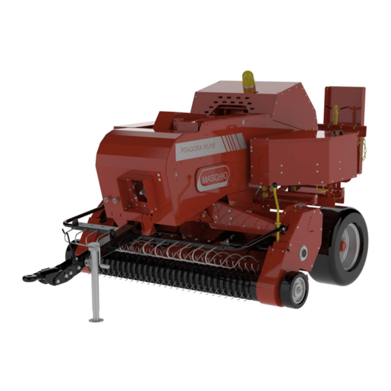
- Page 1 MASCHIO FIENAGIONE S.p.A. PITAGORA INLINE - OPERATOR'S MANUAL Cod. EKE0002OM 2020-09 *) Valido per Paesi UE *) Valid for EU member countries *) Valable dans les Pays UE *) Gilt für EU-Mitgliedsländer *) Válido para Países UE...
-
Page 3: Table Of Contents
1.4. General Aspects for Environmental Science ................... 9 2. TECHNICAL INFORMATION....................10 2.1. Tractor Requirements ..........................10 2.2. PITAGORA INLINE Baler Technical Specifications ................11 3. SAFETY ............................13 3.1. Determination of Safety Precautions in User Guide ................13 3.2. Safety Statements and Accident Preventer Regulations Personal Safety ..........13 3.3. - Page 4 OPERATOR'S MANUAL ENGLISH 5.9. Piston Bearing, Rail and Blade Adjustment ..................64 5.10. Needle Saddle Lever Adjustment ......................68 5.11. Safety Latch Adjustment and Maintenance ................... 68 5.12. Needle Saddle Lining..........................71 5.13. Knotter Set Adjustments ........................74 5.14. Needle Adjustment ..........................78 5.15.
-
Page 5: Identification
OPERATOR'S MANUAL ENGLISH IDENTIFICATION Every single equipment is equipped with identification plate (Fig. 1) whose data shows: 1. Mark and address of the Manufacturer; 2. Designation of the machine; 3. Type of machine; 4. Serial number of the machine; 5. Max. unladen mass (kg); 6. - Page 6 OPERATOR'S MANUAL ENGLISH Chassis ID No. is located at the bottom of the transmission Chassis ID No. is located on the right front hood cover Cod. EKE0002OM...
-
Page 7: General Information
Agricultural bale substances like grass and hay are compressed as standard rectangle bales in the bale chamber. Stable bale chamber of square baler PITAGORA INLINE can achieve compressing bales in size approximately 36 cm x 46 cm and the size of bales can be changed optionally. -
Page 8: Certification
OPERATOR'S MANUAL ENGLISH 1.3.2. Certification Our company has Quality Management System K-Q TSE-ISO-EN 9001-2015 certificate. Cod. EKE0002OM... -
Page 9: Information Required For Questions And Orders
1.3.4. Intended Operation PITAGORA INLINE balers are designed for standard agricultural use only. Any other use does not conform with the intended use. Manufacturer cannot be held liable for any inappropriate use at operator’s own risk. -
Page 10: Technical Information
OPERATOR'S MANUAL ENGLISH 2. TECHNICAL INFORMATION 2.1. Tractor Requirements • Road-drive is permitted only if the bale chamber is empty. • Maximum permitted speed: 20 kmph • As for the machines that are not equipped with brake, deadweight of the tractor should meet the given specifications or otherwise at least have a weight suitable with deadweight of the baler. -
Page 11: Pitagora Inline Baler Technical Specifications
OPERATOR'S MANUAL ENGLISH 2.2. PITAGORA INLINE Baler Technical Specifications PITAGORA INLINE technical specifications are given in Table 2.2.1. NOTE: Our company reserves the right to make changes on dimensions without notice. Table 2.2.1: PITAGORA INLINE Technical Specifications PITAGORA INLINE PICK-UP SYSTEM... - Page 12 OPERATOR'S MANUAL ENGLISH PITAGORA INLINE Machine Dimensions Fig1 Fig2 Cod. EKE0002OM...
-
Page 13: Safety
OPERATOR'S MANUAL ENGLISH 3. SAFETY 3.1. Determination of Safety Precautions in User Guide Before using the machine, please read this User Manual and obey the safety rules. It is assumed that the customer read all the rules in User Manual of the purchased machine. -
Page 14: Personnel Qualification And Training
OPERATOR'S MANUAL ENGLISH Safety measures in this manual that, if not avoided, may result in personal injuries are indicated with general danger sign. Descriptions attached to the machine must be observed, and must be in legible state. Most agricultural equipment accidents can be prevented by observing a few simple safety measures. -
Page 15: Secure And Conscious Operation
OPERATOR'S MANUAL ENGLISH 3.6. Secure and Conscious Operation • Comply with safety measures specified in this manual, existing accident prevention measures and any internal procedures as well as operation and safety rules instructed by the operator. • Safety measures provided by vehicle manufacturer must also be observed. •... -
Page 16: Protection Of Mechanical Systems
OPERATOR'S MANUAL ENGLISH • Sections operated by external forces (i.e., hydraulics, collector assembly) may result in crushing and cutting injuries! • Set the tools down on the ground, stop the engine and remove ignition key before leaving tractor! • No one should be present between tractor and baler before ensuring that the vehicle is absolutely stopped. - Page 17 OPERATOR'S MANUAL ENGLISH • Ensure that selected PTO shaft tractor speed matches permitted tool speed before installing PTO shaft! • Make sure that no one around the tool is in danger before attaching PTO shaft! • Never connect PTO shaft while engine is running! Stop the engine and remove ignition key when attaching PTO shaft! Safeguard the flywheel using the emergency break.
-
Page 18: Hydraulic System
OPERATOR'S MANUAL ENGLISH • Place the disconnected PTO shaft on recommended connection mount! • Attach the cover on PTO shaft end after removing PTO shaft! • If any damage occurs, fix the problem before operating the machine! 3.7.3. Hydraulic system •... - Page 19 OPERATOR'S MANUAL ENGLISH • Adequate knowledge is appropriate tools are required to install wheels and tires. • Repair work on wheels and tires must be performed by specifically trained people using appropriate installation tools. • Regularly check tire pressures! Maintain recommended pressure for the tires! Cod.
-
Page 20: Safety During Maintenance
3.10. Introduction to Machine Maschio Fienagione baler is equipped with all necessary safety devices. However, it is impossible to eliminate all potential hazards as the guards and equipment may encumber machine functions and capabilities. Cod. EKE0002OM... -
Page 21: Safety Warnings On The Machine
OPERATOR'S MANUAL ENGLISH Appropriate caution signs on the machine warn against hazards! Safety measures are provided by means of pictograms. Important information about location of those signs and their meanings are described below! 3.11. Safety Warnings on the Machine Safety warnings on the machine are depicted with numbers in figure 3.11.1 below. Cod. - Page 22 OPERATOR'S MANUAL ENGLISH Cod. EKE0002OM...
- Page 23 OPERATOR'S MANUAL ENGLISH 1. Caution! Do not operate the machine without reading operating manual first. 2. Caution! Stop the tractor, turn the ignition key off and remove it when performing maintenance and repair on the machine. 3. Crushing hazard! Do not stand between tractor and the machine when baler is running.
- Page 24 OPERATOR'S MANUAL ENGLISH 1. Caution! Do not open and remove machine covers, you may get caught in. 2. Caution, Cutting Hazard! Your hands may get caught while machine is running. Do not open and remove machine covers while machine is running. 3.
- Page 25 OPERATOR'S MANUAL ENGLISH Cod. EKE0002OM...
- Page 26 OPERATOR'S MANUAL ENGLISH Cod. EKE0002OM...
-
Page 27: Hazardous Area
OPERATOR'S MANUAL ENGLISH 3.12. Hazardous Area Do not approach more than distances given in Figures 1 and 2 while machine is running. Otherwise, severe occupational accidents may occur Figure 1 Figure 2 Cod. EKE0002OM... -
Page 28: Machine Starting Instructions
OPERATOR'S MANUAL ENGLISH 4. MACHINE STARTING INSTRUCTIONS 4.1. Commissioning Checks to be performed before commissioning; • Check drawbar bolts and drawbar height. • Check the length of PTO shaft. • Inspect the machine and check if there are any damaged and excessively worn parts. •... -
Page 29: Connecting The Drawbar To Tractor
OPERATOR'S MANUAL ENGLISH 4.2. Connecting the Drawbar to Tractor Drawbar must be connected using an appropriate pin. Safety pin must be installed in its place after making drawbar connection (Figure 1). Drive the tractor in reverse gear until approaching to the baler. Align the strut with baler drawbar and install drawbar pin. Use retainer bolts to keep the drawbar in stable position directly under tractor PTO shaft center line. - Page 30 OPERATOR'S MANUAL ENGLISH Figure 1. Jack The jack can be turned to horizontal position by removing safety pin (2) and jack pin no. (1). (Figure 2). Figure 2. Horizontal jack positioning. After connecting to the tractor, safety pin (2) and jack pin (1) can be removed for horizontal positioning to switch to drive and work state.
-
Page 31: Switching The Machine From Drive Position To Work Position
OPERATOR'S MANUAL ENGLISH Figure 3. Vertical Jack Positioning 4.4. Switching the Machine from Drive Position to Work Position; The machine looks as in Figure 1 when in road/drive position. The jack must be brought to vertical position and locked with jack pin and safety pin. Road/Drive Position Figure 1 Tail bale drop plate must be closed as in Figure 2, and secured with the chain. - Page 32 OPERATOR'S MANUAL ENGLISH Figure 2 Collecting piston (Figure 3) opens until stopper unit (Figure 4) or to a level near stopper unit. Thus, collection unit is lifted up. Cod. EKE0002OM...
- Page 33 OPERATOR'S MANUAL ENGLISH Collection wheel (Figure 5) is adjusted to positions 1, 2 or 3 from height adjustment plate eyelets (Figure 6) using wheel positioning shaft according to terrain conditions. Lock the safety pin after adjustment. The machine looks as in Figure 7 in work position Work Position Figure 7 Tail bale drop plate should be opened as in Figure 8, and the inclination should be...
- Page 34 OPERATOR'S MANUAL ENGLISH Bring collection piston to closed position as shown in Figure 9. Figure 9 Collection unit is lowered and raised via collection piston. Distance of collection harrow to the ground can be adjusted using height adjustment level of the collection unit (Figure 10). Collection harrow height A from the ground must be 50mm-10mm.
- Page 35 OPERATOR'S MANUAL ENGLISH Figure 11 Collection wheel (Figure 12) is adjusted to positions 4, 5 or 6 from collection wheel height adjustment plate eyelets (Figure 13) to upwards position via wheel positioning shaft. After performing the adjustment, lock the safety pin. Cod.
-
Page 36: Connecting The Shaft
PTO shafts. PTO shaft and groove channels are illustrated in Figure 1. Figure 1 PITAGORA INLINE baler has an articulated shaft. The motion taken from PTO shaft via articulated shaft is transmitted to baler. Additionally, power transmission between tractor and machine is not interrupted on rough terrain or in turning positions. - Page 37 OPERATOR'S MANUAL ENGLISH Procedures to follow when connecting the shaft: • Operator must stop the engine, remove the key before installing the shaft, and stay away from the machine until all moving components of the machine stop. • Personal protective equipment (safety shoes and gloves) must be worn. •...
-
Page 38: Connecting Hydraulic Hoses
4.6. Connecting Hydraulic Hoses There is 1 double-action hydraulic piston used on PITAGORA INLINE Baler, and this piston is used to control distance of collection unit from the ground. Collection unit piston output connections (1) and (2) are illustrated in Figure 1. - Page 39 OPERATOR'S MANUAL ENGLISH Figure 2 Female couplings on tractor side are illustrated in Figure 3. Male couplings on the collection piston hoses are connected to female couplings (3) and (4) on tractor side. Push the ring on female coupling forward for removal. It should be pushed forward to seat it in the housing for installation.
-
Page 40: Connecting Electrical System
OPERATOR'S MANUAL ENGLISH 4.7. Connecting Electrical System PITAGORA INLINE Baler power cable (1) is 2x6+5x1 mm TTR NYM cable. Cable color coding and associated units are indicated in Figure 1. Figure 1 Female electric socket (1), Baler side electric socket (2) and Tractor side electric socket (3) of the machine are illustrated in Figure 2. - Page 41 OPERATOR'S MANUAL ENGLISH Locations of electric power cable color code label and other labels on the machine are shown in Figure 3. Figure 3 Cod. EKE0002OM...
-
Page 42: Proper Connection Of Twines To The Machine And Threading Into Needles
Follow the below figures for proper connection of twines to the machine. First, bale twine coils are installed on the machine as illustrated in Figure 1. There are total of 10 bale twine coils provided in left and right twine cabins of PITAGORA INLINE machine. Figure 1... - Page 43 OPERATOR'S MANUAL ENGLISH Thread the bale twine (1) through twine eyelet provided on twine cabinet (2). Then pass the bale twine under spring clamp of the butterfly clamp (3) and thread through twine cup (4) located on the butterfly clamp. (Figure 2) Figure 2 After threading the bale twine through twine cup on the butterfly clamp, thread it through twine cup located on needle saddle (4).
- Page 44 OPERATOR'S MANUAL ENGLISH After threading the twine through twine cup on the needle saddle, thread it through twine cup (5) located under the body as illustrated in Figure 4. Figure 4 After the twine cup located under the body, thread the twine into twine reel (6) as illustrated in Figure 5.
- Page 45 OPERATOR'S MANUAL ENGLISH Tie the twine threaded from the reel to U twist welded plate piece (7) as illustrated in Figure 6. Figure 6 Finally, start the baler and (Figure 7) blank tie the twine once by rotating the star (8). Do not tie the twine a second time.
-
Page 46: Machine Maintenance, Repair And Set-Up Guide
OPERATOR'S MANUAL ENGLISH 5. MACHINE MAINTENANCE, REPAIR AND SET-UP GUIDE 5.1. Bale Form, Weight and Size Settings Bale density and weight is set up via resistance pressure applied on the material passing through the bale chamber. Adjust hay resistance (claw) plates (1) inwards using adjustment bolts (a) and (b) for bale density of dry, quality, flexible weed or short crops. - Page 47 OPERATOR'S MANUAL ENGLISH Figure 2 Dimensions of the 4th bale is measured and weighed after the first bale for weight and size adjustment. If the size and weight do not match desired values, make re-adjustment and measure bale size and weight in the 8th bale. These settings will change when switched to another field, therefore weight and size adjustments must be re-arranged.
-
Page 48: Front Flywheel Tripod Clutch Lining Adjustment
OPERATOR'S MANUAL ENGLISH You can adjust bale size using threaded rod (4) for bale size setting illustrated in Figure 4. You can make short bales in upward position and long bales in downward position. Bales can be formed in 300mm -1350mm sizes. Figure 4 5.2. -
Page 49: Chain And Tension Setting
OPERATOR'S MANUAL ENGLISH Adjustment is required for clutch lining depending on condition of the springs (tensioning springs) after making 10.000 bales on the machine. After new lining replacement, compression spring adjustment should be made as illustrated in Figure 2, at a height of 37 mm (3,7 cm) together with the washer. - Page 50 OPERATOR'S MANUAL ENGLISH Helical Unit Install 12B-1 type helical unit chain (4) as in Figure 3, and check deviation from location no (2). Figure 3 Transmission Unit Main Drive Chain Install 16B-1 type transmission unit main drive chain (5) as illustrated in Figure 4. Tension the chain using chain tension gear (6) and check deviation from location no (2).
-
Page 51: Pick-Up Unit Settings
OPERATOR'S MANUAL ENGLISH Knotter Set Drive Chain Install ASA60-H type knotter set drive chain (7) as illustrated in Figure 5. Tension the chain using chain tensioning gear (8) and check deviation from location no (2). Figure 5 5.4. Pick-Up Unit Settings Height of collection harrows is adjusted using collection height adjustment screw (1). - Page 52 OPERATOR'S MANUAL ENGLISH Harrow height of 50mm from the ground is suitable for most field conditions. If you perform collection too low, it may collect dust and rocks along with the crop. This may damage or wear collecting components. (Figure 2) Figure 2 Collection unit floating spring bears majority of collection group during bale machine operation.
-
Page 53: Auger Settings
5.5. Auger Settings PITAGORA INLINE bale machine is equipped with scrapers (3) to prevent crops jamming in helices (1) on upper part of helical chassis and rolling of crops together with helical blades (2). Proper distancing should be ensured between helical scrapers and helical blades. -
Page 54: Adjustments Following Transmission Chain Breaks (Filler Timing Setting)
OPERATOR'S MANUAL ENGLISH 5.6. Adjustments Following Transmission Chain Breaks (Filler Timing Setting) Procedures to follow when any of the following occurs; new transmission chain is to be installed, or transmission chain breaks or the 3 share bolts holding the flange on transmission chain gear breaks;... - Page 55 OPERATOR'S MANUAL ENGLISH • Turn the flywheel and align M12X45 hayfork shear bolt (3) on transmission chain with the bolt on transmission cover (4) (Figure 3). Figure 3 • Align M6X35 knotter set shear bolt (6) located on hayfork group drive chain gear (5) with straight angle to the ground as shown in Figure 4.
-
Page 56: Adjustments Following Knotter Set Drive Chain Breakage (Center Adjustment)
OPERATOR'S MANUAL ENGLISH • Install transmission chain as illustrated in the figure and tension the chain from tensioning section (9). Install chain seam point from section no (8) for ease of assembly. (Figure 5) Figure 5 5.7. Adjustments Following Knotter Drive Chain Breakage... - Page 57 OPERATOR'S MANUAL ENGLISH • Move piston braking pivot (2) to forward position. When the fork is removed, piston braking pivot spring pull will come to desired position. Figure 2 • Facing rear of the machine, turn flywheel clockwise. (Figure 3) Figure 3 Cod.
- Page 58 OPERATOR'S MANUAL ENGLISH • Press the transmission lever (3) to piston brake pivot (2) as shown in Figure 4. Transmission chain gear shearbolt flange and hayfork drive chain shearbolt flange will appear as illustrated in Figure 5. Figure 4 Figure 5 Cod.
- Page 59 OPERATOR'S MANUAL ENGLISH • Release bale size adjustment mechanism (4) and bale size adjustment seat (5) as illustrated in Figure 6. Figure 6 • (Figure 7) Turn the knotter set drive gear (6) counter-clockwise and press the interior safety latch seat (7), cast drive rod (8) against automatic latch reel (9) which is also located inside.
- Page 60 OPERATOR'S MANUAL ENGLISH Figure 8 • Run the ASA60-H Knotter set chain (10) over knotter set drive gear and connect from no (11). Once installed, tension the chain using tension gear no (12). (Figure 9) Figure 9 Cod. EKE0002OM...
- Page 61 OPERATOR'S MANUAL ENGLISH • Pull piston brake pivot backwards and re-install the fork (1) driving piston brake pivot (Figure 10) Figure 10 • Turn the flywheel 1 cycle before threading twines into needles, tap the bale size adjustment seat (5) against automatic latch (13), and bring the bale size adjustment mechanism (4) to normal position.
-
Page 62: Adjustments To Perform When Shear Bolt Break
ENGLISH 5.8. Adjustments to Perform When Shear Bolt Break There are 3 each shear bolts on PITAGORA INLINE Machine. Flywheel Unit There is 1 each M10X65mm shear bolt (1) on the flywheel unit. If it breaks, turn the flywheel first, and remove broken bolt pieces from bushings. After cleaning is complete, align the shear bolt bushing hole on flywheel rotation arm with the hole on flywheel, and insert M10X65mm shear bolt through both holes.( Figure 1) - Page 63 OPERATOR'S MANUAL ENGLISH Figure 2 Hayfork Unit There is 1 each M10X65mm knotter set shear bolt (3) on the hayfork unit. If it breaks, first turn the chain gear located on hayfork unit and remove broken bolt pieces from shear bolt bushings.
-
Page 64: Piston Bearing, Rail And Blade Adjustment
OPERATOR'S MANUAL ENGLISH 5.9. Piston Bearing, Rail and Blade Adjustment First, install the fixed blades (1), and supply 0,5-1mm shim plates (3) under fixed blades, leaving 1- 1,5 mm space with the bottom rails (2). (Figures 1,2,3) Before placing the piston inside the baling chamber, park the tractor and bale machine on a solid ground. - Page 65 OPERATOR'S MANUAL ENGLISH Figure 4 Figure 5 Cod. EKE0002OM...
- Page 66 OPERATOR'S MANUAL ENGLISH Remove the plastic covers (6) located at the two input opening on the baling room to center the piston horizontally. Turn the flywheel manually until you see piston horizontal wheel bearing (7) bolts (8) from the input openings. Loosen horizontal wheel bearings that are visible from input openings and touch them against L twist rails (9) and tighten using socket wrench.
- Page 67 OPERATOR'S MANUAL ENGLISH Figure 8 Before centering pistons vertically, rotate the flywheel 1 cycle to check its horizontal centering. There are two fixed rails at the bottom of bale machine. The top two L twist rail can be adjusted up and down. Move the piston all the way back and start vertical centering of the piston.
-
Page 68: Needle Saddle Lever Adjustment
OPERATOR'S MANUAL ENGLISH 5.10. Needle Saddle Lever Adjustment Needle saddle lever length should be adjusted as 515 mm (51,5 cm). Figure 1 5.11. Safety Latch Adjustment and Maintenance Remove safe stop spring (2) from safety latch connection plate. Remove the fork (3) from the connection plate. - Page 69 OPERATOR'S MANUAL ENGLISH Figure 1 Cod. EKE0002OM...
- Page 70 OPERATOR'S MANUAL ENGLISH Figure 2 Figure 3 Cod. EKE0002OM...
-
Page 71: Needle Saddle Lining
OPERATOR'S MANUAL ENGLISH 5.12. Needle Saddle Lining Compression springs (1) inserting into M10X70 adjustment bolts that are used to adjust needle saddle lining must be tightened between 29-31 mm measured from the washer. (Figure 1,2) Figure 1 Cod. EKE0002OM... - Page 72 OPERATOR'S MANUAL ENGLISH Figure 2 Compression springs (4) inserting into M6X70 adjustment bolts (3) on knotter set lining must be tightened between 40-43 mm measured from the washer. (Figure 3) Note: Knotter set linings should be re-adjusted after 10.000 bales depending on the lining bolt wear amount.
- Page 73 OPERATOR'S MANUAL ENGLISH Fiigure 3 Cod. EKE0002OM...
-
Page 74: Knotter Set Adjustments
OPERATOR'S MANUAL ENGLISH 5.13. Knotter Set Adjustments Knotter Set adjustments and nuts should be in accordance with the relations in Troubleshooting Solution Table in Table 5.13.1. The same table as well as Figures 1-2 and 3 should be used to troubleshoot twine pulling mechanism. Figure 1 Cod. - Page 75 OPERATOR'S MANUAL ENGLISH Figure 2 Cod. EKE0002OM...
- Page 76 OPERATOR'S MANUAL ENGLISH Figure 3 Cod. EKE0002OM...
- Page 77 OPERATOR'S MANUAL ENGLISH Table 5.13.1: Knotter Set Troubleshooting and Solutions FORM OF KNOT PROBLEMS CAUSES SOLUTIONS Standard knot. Clean-cut tips of twine. Curlings occur during Please screw the nut knotting. Curling Adjustment of hook spring is increasing spring tension sticks hook latch and loose by quarter round.
-
Page 78: Needle Adjustment
OPERATOR'S MANUAL ENGLISH 5.14. Needle Adjustment Performing needle adjustments; For Deering Knotter Set; • Loosen needle locking bolts (1) and bring the needle saddle drive rod (2) to upper dead point. (Figure 1) Figure 1 • When the needle saddle drive rod is in this position, distance between needle tip (3) and pinion gear (4) center should be in the range of 100-110 mm. - Page 79 OPERATOR'S MANUAL ENGLISH Figure 2 Cod. EKE0002OM...
- Page 80 OPERATOR'S MANUAL ENGLISH • Then, turn the needle saddle drive rod (2) and protrude needle tip (3) a little out of pinion gear (4) top surface to check it. The distance between star plate (5) and needle should be 3-5 mm in this position. (Figure 3.) Figure 3 Cod.
- Page 81 OPERATOR'S MANUAL ENGLISH For Cormick Knotter Set; • Loosen needle adjustment bolts (1) and protrude needle (3) tip from needle saddle drive rod at a distance of 165mm from the horizontal table. Figure 4. Figure 4 Cod. EKE0002OM...
- Page 82 OPERATOR'S MANUAL ENGLISH • Then, measure the distance between twine puller plate (7) and needle (3), and adjust to 3 - 5 mm, and tighten needle adjustment bolts to secure needles. Figure 5. Figure 5 Cod. EKE0002OM...
-
Page 83: Winter Maintenance And Storage
Complete necessary repair works immediately after harvest season. Make a list of all required spare parts. Systematic care will reduce the work load of Maschio Fienagione service, and you can be sure of a good machine operation at the beginning of new season. -
Page 84: Lubrication
OPERATOR'S MANUAL ENGLISH 6. LUBRICATION Regular lubrication and maintenance plays a vital role in keeping your equipment durable, long-lasting. Use of appropriate fuel, lubricant, grease and filters, keeping the system clean will extend life cycle of your machine and parts, and ensure a long and efficient use. - Page 85 OPERATOR'S MANUAL ENGLISH Shaft Maintenance; Shaft joints and clutches must be lubricated from grease nipples on daily basis. Shafts must be used with their housings. Housing chains must be secured to prevent rotation of housing together with the shaft itself. Deformed shafts and housings must be replaced with a new one.
- Page 86 OPERATOR'S MANUAL ENGLISH For Drawbar; Considering operation time of drawbar, lubricate every 50 hours using grease. (Figure 3.) Figure 3 Star Unit; Considering operation time of star unit, lubricate every 50 hours using grease. (Figure Figure 4 Cod. EKE0002OM...
- Page 87 OPERATOR'S MANUAL ENGLISH For Flywheel; Considering operation time of drawbar, lubricate every 10 hours on daily basis using grease. (Figure 5.) Figure 5 For Knotter Set; Components on the Knotter Set unit are in continuous motion. Therefore, considering continuous operation time, needle saddle drive rod, eccentric shaft bearings, needle saddle bearing and bale size adjustment piece should be lubricated on daily basis before starting the shift.
- Page 88 OPERATOR'S MANUAL ENGLISH Group UCFC bearings located on knotter set unit, group shaft and spacing bushings move continuously. Therefore, considering operation time, lubricate every 10 hours on daily basis using grease. (Figure 7.) Figure 7 Considering operation time of knotter set, lubricate every 10 hours on daily basis before starting operation using grease.
- Page 89 OPERATOR'S MANUAL ENGLISH For Ratchet Unit; Crop input passage can be clogged from time to time due to crop jamming in collection unit and helices. Corps must be removed by reversing helices and collection harrows. Ratchet unit enables reverse rotation of collection harrows and helices without changing position of hayfork sheets.
- Page 90 OPERATOR'S MANUAL ENGLISH For Hayfork Bearing and Hayfork Unit; Considering operation time of pillow block in hayfork area, lubricate every 10 hours on daily basis before starting operation using grease. (Figure 10). Figure 10 Rotate the flywheel clockwise and align the grease nipple on the hayfork rod with lubricant filling opening (1), and lubricate hayfork unit using grease every 10 hours.
- Page 91 OPERATOR'S MANUAL ENGLISH For Chains; Molding may occur if chains are not lubricated, which reduces life-cycle of the chain. Molded chains also damage the chain gears on which they are installed. Therefore, pay special attention to chain lubrication. Do not apply grease on chains. You can use oil no. 10. If the machine is operated on daily basis, lubricate all the chains present on th machine once in every ten days using a brush.
- Page 92 OPERATOR'S MANUAL ENGLISH For transmission; PITAGORA INLINE baler transmission is lubricated using 4.8 KG No. 85W140 transmission oil. Change transmission oil after every 50 thousand bales. Park the machine on a straight, balanced surface before oil change. Open the vent cap (1) located on top.
-
Page 93: Diagnostic And Troubleshooting
OPERATOR'S MANUAL ENGLISH 7. DIAGNOSTIC AND TROUBLESHOOTING Some of the possible problems that may occur on PITAGORA INLINE Baler and their solutions are given in the following table. 7.1. PTO Shaft Area PTO shaft area problems and solutions are given in Table 7.1.1. -
Page 94: Collector Area
OPERATOR'S MANUAL ENGLISH PROBLEM CAUSES SOLUTION 4.1) Lock bolt torque is wrong 4.1) Install correct component and or only one tempered tighten to correct torque. washer is placed under the 4.2) Install correct tempered bolt. washers. 4.2) Wrong size of washer(s) 4.3) Flywheel should freely rotate placed under bolt head. -
Page 95: Electrical Diagram
Electrical Diagram PITAGORA INLINE Baler electrical drawing is given in Figure 1. PITAGORA INLINE Baler Electrical Drawing Figure 1 7.5. Hydraulic Circuit Diagram PITAGORA INLINE Baler hydraulic circuit diagram is illustrated in Figure 2. Hydraulic Circuit Diagram Figure 2 Cod. EKE0002OM... -
Page 96: Circumstances And Components Excluded From Warranty
OPERATOR'S MANUAL ENGLISH 8. CIRCUMSTANCES AND COMPONENTS EXCLUDED FROM WARRANTY Damages that may arise from use of the machine with unauthorized crops (Corn, Peanut, Soiled Stubble Bale, etc.) are excluded from warranty coverage. Damages and failures that may arise from adjustments, corrections and maintenance are excluded from warranty coverage. -
Page 97: Initial Start-Up Safety Information Form
OPERATOR'S MANUAL ENGLISH INITIAL START-UP SAFETY INFORMATION FORM Safety Most agricultural equipment accidents can be prevented by observing a few simple safety measures. • Do not perform any cleaning, lubrication or adjustment work while baler is in operation (moving) or tractor engine is running. Listen and visually check to see presence of any rotating parts. - Page 98 • Applicable traffic rules on public roads must be followed. AUTHORIZED OPERATION PITAGORA INLINE balers are designed for standard agricultural use only. Any other use does not conform with the intended use. Manufacturer cannot be held liable for any inappropriate use at operator’s own risk.
- Page 99 OPERATOR'S MANUAL ENGLISH MACHINE INFORMATION Machine Name Production Year : Chassis ID No AUTHORIZED SERVICE CUSTOMER INFORMATION Service Name : ID Number : Name Surname Contact No : Contact No : Address : Address : Description Description SIGNATURE : STAMP & SIGNATURE: Cod.
- Page 100 EMPLOYEZ TOUJOURS LES PIECES DE RECHANGE ORIGINALES UTILIZAR SIEMPRE REPUESTOS ORIGINALES Servizio Assistenza Tecnica - After Sales Service Servizio Ricambi - Spare Parts Service DEALER: MASCHIO Fienagione S.p.A. ООО МАСКИО-ГАСПАРДО РУССИЯ MASCHIO GASPARDO MASCHIO FRANCE Sarl Sede legale Cremona 404130, ВОЛЖСКИЙ, Poland sp z.o.o.
Need help?
Do you have a question about the PITAGORA INLINE and is the answer not in the manual?
Questions and answers