
Related Manuals for Prochem BLAZER PLUS


Summary of Contents for Prochem BLAZER PLUS
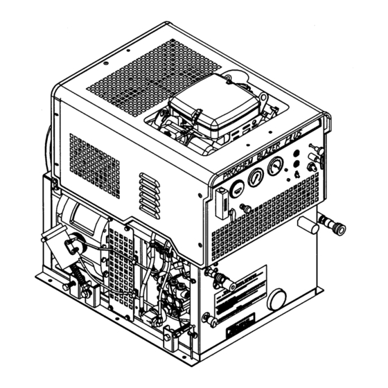
- Page 1 Cleaning Unit Mobile Operating Instructions (ENG) MODELS: BLAZER PLUS Read instructions before operating the machine. 980073 11/26/03...
-
Page 2: Machine Data Log/Overview
Phone Number: _________________________________________________________________________________________ Welcome…and congratulations on your purchase of the BLAZER PLUS Mobile Cleaning Unit. This instruction manual is a guide for operating and servicing your PROCHEM unit. Read this manual completely before installing or operating this unit. This unit offers you personal convenience. All of your instrumentation and controls have been positioned to give you easy access for operation and daily maintenance. -
Page 3: Table Of Contents
TABLE OF CONTENTS Machine Data Log/Overview......1 MAINTENANCE & SERVICE Table of Contents ...........2 Maintenance HOW TO USE THIS MANUAL Maintenance Schedule......4-1 Engine............4-2 Vacuum Pump......... 4-3 How to use this Manual........1-1 Water Pump..........4-4 Strainer Basket (Waste Tank) ....4-4 SAFETY Bypass Manifold ........ -
Page 4: Table Of Contents
TABLE OF CONTENTS PARTS LIST Front Panel.........5-1 Framework .........5-3 Engine ..........5-5 Vacuum Pump ........5-9 Water Pump........5-11 Chemical Pump........5-15 Bypass Manifold.........5-19 Bypass Solenoid ........5-21 Water Inlet..........5-23 Water Box ..........5-25 Vacuum Exhaust Heat Exchanger ..5-27 Vacuum Heat Exchanger....5-29 Waste Tank ........5-31 Automatic Pumpout......5-33 Hose Accessories ......5-37 Wand-Tri-Jet ........5-39 Wand-Dual-Jet........5-41... -
Page 5: How To Use This Manual
HOW TO USE THIS MANUAL The SAFETY section contains important information This manual contains the following sections: regarding hazard or unsafe practices of the machine. Levels of hazards is identified that could HOW TO USE THIS MANUAL result in product or personal injury, or severe injury SAFETY resulting in death. -
Page 6: Safety Instructions
IMPORTANT SAFETY INSTRUCTIONS When using this machine, basic precaution must always be followed, including the following: READ ALL INSTRUCTIONS BEFORE USING THIS MACHINE. These symbols mean WARNING or CAUTION. Failure to follow warnings and cautions could result in fatality, personal injury to yourself and/or others, or property damage. - Page 7 DO NOT leave the vehicle engine running while operating this unit. Dangerous Acid, Explosive Gases! Batteries contain sulfuric acid. To prevent acid burns, avoid contact with skin, eyes and clothing. Batteries produce explosive hydrogen gas while being charged. To prevent a fire or explosion, charge batteries only in well ventilated areas.
-
Page 8: Hazard Intensity Level
Order Part #48-941212 to get a complete set of decals (safety and instrumentation) for your BLAZER PLUS cleaning unit. The following decals must be placed in a prominent spot on the vehicle that your unit is to be installed in where access is given to operate the unit. See next page for suggested locations for these decal. - Page 9 HAZARD INTENSITY LEVEL The decals should be placed in a prominent spot on the vehicle where access is given to operate the unit. The illustrations above suggest the location and placement of the decals. When placing the decals, be sure the area is clean of any dirt and possible wax build-up.
-
Page 10: Technical Specifications
192 inch/lbs 16 foot/lbs JET SIZING: Prochem recommends floor tool tip sizing not exceed a total of “.04”. Using larger jet sizes on your BLAZER PLUS may reduce cleaning temperatures. Example: Dual jet wand uses two 11002 jets. (110° spray angle w/ 02 orifice) -
Page 11: Receiving Your Unit
15. Winterizing loop hose. Part #10-805380. ACCEPTANCE OF SHIPMENT 16. Upholstery tool and stair tool. Every part of your PROCHEM BLAZER PLUS 17. Extra wands. cleaning unit was carefully checked, tested, and inspected before it left our manufacturing plant. Upon 18. -
Page 12: Installation Requirements
6. We highly recommend using a galvanized drip tray under the console (Part #56-501607). 7. If using a trailer, the BLAZER PLUS console should be positioned so that it balances properly with respect to the axle. Ten percent (10%) of the overall unit weight (without accessories or water) should be on the tongue. - Page 13 3-1/2 grains, we highly recommend a suitable water The PROCHEM BLAZER PLUS, due to its chemical softener be installed. If using a water softener, it must injection pump design, can be used with a variety of...
-
Page 14: Water Pumping System
OPERATION WATER PUMPING SYSTEM A small amount of hot water constantly bleeds through the bypass manifold, which contains a small orifice, to the water box. See Figures 1 and 2. A temperature switch on the heat exchanger outlet Cold water enters the console through the water will shut down the engine if the water temperature inlet connection located on the lower front panel. - Page 15 OPERATION The vacuum exhaust heat exchanger utilizes The primary heat exchanger is an engine exhaust vacuum pump exhaust as it is leaves the vacuum chamber containing a stainless steel heating coil. pump. The warm air flows through a radiator-type Water flows through the coil and is heated by the heat exchanger prior to discharging out to the engine exhaust as it leaves the engine.
- Page 16 OPERATION FIGURE 1 BLAZER 980073 09/16/02...
- Page 17 OPERATION FIGURE 2 BLAZER 980073 09/16/02...
-
Page 18: Vacuum System
OPERATION VACUUM SYSTEM A level sensor switch located near the top of the Vacuum flow is initiated by the vacuum pump, with waste tank will shut the unit down before the waste air and water being drawn into the vacuum inlet at tank reaches its full capacity. -
Page 19: Chemical System
OPERATION Next, the chemical pump injects the chemical CHEMICAL PUMPING SYSTEM through a check valve to the 3-way selector valve on the control panel. This valve may turn the chemical The chemical is drawn from the chemical container flow ON, OFF, or PRIME the chemical pump. through a strainer into the flow meter. -
Page 20: Water Supply Connection
OPERATION FILLING AUXILIARY WATER TANK Operate this unit and equipment only in a well- Your cleaning unit may be equipped with an auxiliary ventilated area. Exhaust fumes contain carbon water tank mounted underneath the console. To fill monoxide which is an odorless and deadly the auxiliary water tank: poison that can cause severe injury or fatality. - Page 21 OPERATION WATER PRESSURE GAUGE VACUUM GAUGE HOURMETER MAIN CIRCUIT BREAKER PUMP-OUT CIRCUIT BREAKER CHOKE CONTROL THROTTLE ON/OFF FLOWMETER IGNITION SWITCH CHEMICAL PRIMING VALVE CHEMICAL PUMP-OUT METERING SWITCH VALVE SOLUTION OUTLET PRESSURE ENGINE REGULATOR EXHAUST OUTLET WATER INLET CONDENSED OPERATING INSTRUCTIONS VACUUM INLET ON WASTE...
-
Page 22: Vacuum Hose
5 minutes with vacuum blocked off. Allow 5 JET SIZING minutes maximum to warm up. Prochem recommends floor tool tip sizing not PRIMING THE CHEMICAL PUMP exceed a total of “04”. Using larger jet sizes on your BLAZER PLUS may reduce cleaning temperatures. -
Page 23: Waste Pump
OPERATION WASTE PUMP 2. Normally, chemical is applied on the push stroke of the wand when cleaning, and vacuuming is done on the pull stroke. For heavily soiled 1. If your unit is equipped with an automatic waste carpets the wand may be used in a scrubbing pump, connect one end of a garden hose to the manner, applying chemical in both push and pull pump-out connection on the console and the... -
Page 24: Shutdown & Daily Maintenance
3. Position the throttle control to approximately 3/4 of the way out, but no less than 1/2 out. NOTE: When replacing this filter, we recommend using the stainless steel PROCHEM filter (Part 4. Disconnect the vacuum hoses from the unit. #14-806518) only. This will prevent rust and corrosion from entering the vacuum system. - Page 25 OPERATION ADDING ANTI–FREEZE TO YOUR 7. Shut-down the unit. Attach the winterizing loop hose with attachment, Part #10-805380, to the UNIT: solution outlet connection and the water inlet connection. Restart the unit. 1. Shut off the water supply. Disconnect the water inlet hose from the front of your console.
-
Page 26: Removing Anti-Freeze
OPERATION 7. Place the chemical prime hose into the REMOVING ANTI–FREEZE FROM THE approved container. Submerge the chemical UNIT inlet hose in water. Turn the chemical valve to the PRIME position until clear water comes 1. Connect one end of the loop hose to the solution through the prime hose, and then remove the outlet connection. -
Page 27: Maintenance
MAINTENANCE SERVICE SCHEDULE Engine Daily Check engine oil level.*** Fill no proper level. Vacuum pump Daily Spray WD-40 in lubrication cup at front of console for 5 seconds. Water pump Daily Check oil level.** Fill to proper level. Vacuum inlet filter (in waste tank) Daily* Clean filter, inspect, replace if damaged. -
Page 28: Maintenance Schedule
Use high quality detergent oil of API (American planned preventative maintenance program will Petroleum Institute) service class SF or SG. assure that your PROCHEM BLAZER PLUS has Select the viscosity based on the air optimum performance, a long operating life, and a temperature at the time of operation as shown in minimal amount of "down"... -
Page 29: Vacuum Pump
NOTE: AEON PD (Part # 05-008039) is the oil which 3. Drain, flush and replace oil every 1500 Prochem puts in the vacuum pump at the factory. hours or yearly, whichever comes first. Topping off or adding petroleum oil to synthetic oil Change oil more frequently if inspection so is NOT recommended. -
Page 30: Water Pump
Grasping filter by the screen may collapse or ruin the filter. NOTE: When replacing this filter, we recommend using a stainless steel PROCHEM filter (#14-806518) only. This will prevent rust and corrosion from entering the vacuum system. -
Page 31: Drive Belts, Pulleys And Hubs
MAINTENANCE DRIVE BELTS, PULLEYS, & HUBS Place a straight-edge across the top of belt. There should be no more than 1/2" deflection in the center of the belt, halfway 1. Check pulley set screws and/or hub cap screws after between the pulleys. If there is too much the first 25 hours and then again at 100 hours. -
Page 32: Chemical Pump, Chemical
MAINTENANCE Y–STRAINER (OUTLET) NITROGEN ACCUMULATOR Inspect the Y-strainer after the first week of running Check the nitrogen pre-charge at least once a year. the unit by unscrewing the screen and remove any Recharge the accumulator and replace the bladder, accumulated debris. Inspect the strainer again at 2 when needed. -
Page 33: Battery
MAINTENANCE BATTERY ENGINE EXHAUST HEAT EXCHANGER Dangerous Acid, Explosive Gases! If an engine is not properly maintained, the Batteries contain sulfuric acid. To prevent acid exhaust gases may deposit carbon on the burns, avoid contact with skin, eyes and clothing. outside of the heat exchanger coil and affect the Batteries produce explosive hydrogen gas while cleaning solution temperature. -
Page 34: General Service Adjustments
MAINTENANCE VACUUM EXHAUST HEAT EXCHANGER VACUUM PUMP DRIVE BELTS Removing and cleaning the vacuum exhaust pre- To tighten the vacuum pump belts: heater core is recommended as needed or if the unit was operated with the vacuum inlet filter damaged, 1. -
Page 35: Bypass Manifold
MAINTENANCE BYPASS MANIFOLD 4. Clean the poppet and spring, inspect for wear or damage, replace as needed. Clean the bypass strainer and orifice weekly, using 5. Re-assemble the check valve. Start the seat by the following guidelines: hand, tighten using a 5/16" Allen wrench. DO NOT over-tighten seat. -
Page 36: Packing Nut Adjustment
MAINTENANCE PACKING NUT ADJUSTMENT FOR We recommend that you lubricate the pressure regulator o-ring every 50 hours, or whenever CHEMICAL METERING AND required. If you do not, the stem may become CHEMICAL SELECTOR VALVES seized due to inadequate lubrication. If this occurs: Examine the packing nut on the metering and a) Shut-down the unit. -
Page 37: Waste Tank To Console Connection
3. Connect the long section of 2-7/8" I.D. (for Before disconnecting the negative (-) ground Blazer Plus) or 2” I.D. (for Blazer) internal cable, make sure all switches are OFF. If ON, a vacuum hose to the vacuum outlet tube on the... - Page 38 MAINTENANCE WASTE TANK TO CONSOLE CONNECTION FIGURE 3 SPECIAL INSTRUCTIONS: 1. Cut hoses to fit, if necessary. 2. When cutting hoses, make certain that the cutting blade is facing away from your hands, fingers, or any other part of your body to avoid injury.
-
Page 39: Auxiliary Water Tank Connection
MAINTENANCE AUXILIARY WATER TANK CONNECTION 2. Connect the demand pump cord to the 2-pole connector on the console (located on the left side of the console near the vacuum pump.) Your cleaning unit may be equipped with an auxiliary water tank mounted underneath the console. The figure below illustrates how the demand pump When using the auxiliary water tank as your works with the auxiliary water tank and how it... -
Page 40: Troubleshooting
MAINTENANCE In addition, prior to proceeding, you can save TROUBLESHOOTING time by checking that: DO NOT service this unit while it is running. The 1. The water supply is ON. high-speed mechanical parts as well as high temperature components may result in severe 2. - Page 41 MAINTENANCE PROBLEM CAUSE SOLUTION Water supply is turned off or the float Turn the water supply on or up. Check valve is stuck or improperly adjusted. for kinks in the water supply hose. NOTE: This may also cause the water Examine the float valve and adjust or pressure switch to shut the unit down.
- Page 42 MAINTENANCE PROBLEM CAUSE SOLUTION Examine the tubing between the vacuum Vacuum gauge is giving an improper relief valve and the vacuum gauge and reading. remove any blockage. Vacuum hose(s) is damaged, Inspect all lines, remove accumulated causing a suction leak. debris Waste tank gasket not sealing Inspect the gasket.
- Page 43 MAINTENANCE PROBLEM CAUSE SOLUTION After inspecting the unit to determine the Main circuit breaker on the control cause of the tripped circuit breaker, press panel has been tripped. the reset button. Clean, tighten, or replace the battery Loose or corroded battery. terminals.
- Page 44 Engine RPM is low. Replace, if necessary. Soak coil section at a radiator shop. Boil Engine exhaust heat exchanger is tank or soak in PROCHEM Industrial carbon-coated on outside of coil. cleaner. Damaged or plugged radiator core Remove and inspect cores. Replace, if in vacuum exhaust heat exchanger.
-
Page 45: Front Panel
FRONT PANEL 13,14,15,16 24,26 CONDENSED OPERATING INSTRUCTIONS 26,27 BLAZER 980073 09/16/02... - Page 46 87162 WASHER, 1/4 SPLIT LOCK 56-502120 ASSY, LWR FR PNL BLZR 48-941197 DECAL, CONDENSED INTRUCT NOT SHOWN 48-941195 DECAL, HOOD PROCHEM TM NOT SHOWN 48-941212 DECAL, WARN & INTRUCT NOT SHOWN 48-941391 DECAL, PNL BLZR NOT SHOWN BLAZER 980073 09/16/02...
-
Page 47: Framework
FRAMEWORK BLAZER 980073 09/16/02... - Page 48 PAD, VIBR CONTR PNL MT 61-951194 ASSY, DIPSTICK & CABLE 50-501988 CLIP, DIPSTICK 61-951446 ASSY, HOOD INCLUDES 17-20 00-000400 SCR, 1/4-20 X 1/2” THRUSHD PHIL 27-100221 TRIM, FLEX 48-941195 DECAL, HOOD PROCHEM 50-501851 HOOD, BLAZER 58-700023 PAD, 1/4 TURN VIBR BLAZER 980073 09/16/02...
-
Page 49: Engine
ENGINE BLAZER 980073 09/16/02... - Page 50 ENGINE SERIAL NO. PART NO. DESCRIPTION NOTES: FROM 61-951450 ENGINE 42-902005 B&S CARTRIDGE AIR CLNR 394-018 42-902006 ELEMENT (OUTER), AIR CLEANER 40-902147 ENG, B&S 18HP VTWIN OHV 52-501935 PULLEY, ENGINE 87083 WASHER, 5/16 SPLIT LOCK PLTD 70258 SWITCH, MXB SAFETY 44-802313 BELT, AX36 57031...
- Page 51 ENGINE TO NEGATIVE (-) BATTERY TERMINAL TO POSITIVE (+) BATTERY TERMINAL TO BULKHEAD ADAPTER ON VEHICLE FLOOR BLAZER 980073 09/16/02...
- Page 52 ENGINE SERIAL NO. PART NO. DESCRIPTION NOTES: FROM 42-902176 B&S MOTOR, START 64-950060 CABLE, BAT X 8” BLK 02-000066 FLATWASHER, 1/4 87162 WASHER, 1/4 SPLIT LOCK PLTD 70270 SCR, 1/4-20 X 3/4 HHCS PLTD 35-901002 SOLENOID, STARTER 87083 WASHER, 5/16 SPLIT LOCK PLTD 64-950499 CABLE, BAT X 61”...
-
Page 53: Vacuum Pump
VACUUM PUMP TO WASTE TANK TO VACUUM GREASE MUFFLER FITTING TO VACUUM GAUGE TO OIL CUP BLAZER 980073 09/16/02... -
Page 54: Water Pump
WATER PUMP SERIAL NO. PART NO. DESCRIPTION NOTES: FROM 70266 SCR, 3/8-16 X 1” HHCS GR5 PLTD 70357 SCR, 1/2-13 X 3 FULL THREADS 00-000340 SCR, MACH 5/16-18 X 1” GR8 02-000057 FLATWASHER, 1/2 HEAVY 87171 WASHER, 3/8 FLAT 87163 WASHER, 3/8 SPLIT LOCK 05-008039 OIL, AEON PD... - Page 55 WATER PUMP TO WATER BOX TO PRESSURE MANIFOLD TO FRONT ENGINE PULLEY TO CHEMICAL PRIME VALVE TO TOP OF FLOWMETER BLAZER 980073 09/16/02 5-11...
- Page 56 WATER PUMP SERIAL NO. PART NO. DESCRIPTION NOTES: FROM 00-000277 SCR, MACH 6MM X 14MM 00-000340 SCR, MACH 5/16X18 X 1” GR8 00-000472 SCR, 1/2-13 X 5 GR2 57111 NUT, 3/8-16 HEX 87162 WASHER, 1/4 SPLIT LOCK 02-000057 FLATWASHER, 1/2” HEAVY 02-000066 FLATWASHER, 1/4 87171...
- Page 57 WATER PUMP BLAZER 980073 09/16/02 5-13...
- Page 58 WATER PUMP SERIAL NO. PART NO. DESCRIPTION NOTES: FROM 42-809238 CAP, OIL FILTER 42-809239 O-RING, OIL FILL CAP 42-809249 WASHER, KEYHOLE M18 42-809381 SLINGER, BARRIER 42-809394 O-RING, BEARING CVR 42-809401 COVER, CRANKCASE 42-809402 O-FING, CRANK CVR 42-809403 MANIFOLD, HEAD 42-809404 PLUG, VALVE 42-809405 RETAINER, SEAL...
- Page 59 CHEMICAL SYSTEM SOLUTION OUTLET FROM WATER PUMP TO CEHMICAL RESERVOIR BLAZER 980073 09/16/02 5-15...
- Page 60 CHEMICAL SYSTEM SERIAL NO. PART NO. DESCRIPTION NOTES: FROM 18-808513 FLOW METER 18FP 87165 WASHER, #10 SPLIT LOCK 00-000065 SCR, 10-32 X 3/8” PNHD 12-800093 FTTG, BRB 1/8P X 5/16H 03-000065 CLAMP, HOSE #4 SPOTTER SST 09-805421 HOSE, BRAID 5/16 X 54” 14-806506 SCREEN, 1/8FP 12-800040...
- Page 61 PRESSURE MANIFOLD TO PRESSURE GAUGE TO EXHAUST HEAT EXCHANGER TO BYPASS MANIFOLD TO VACUUM HEAT EXCHANGER BLAZER 980073 09/16/02 5-17...
- Page 62 PRESSURE MANIFOLD SERIAL NO. PART NO. DESCRIPTION NOTES: FROM 00-000210 SCR, 1/4-20 X 3/4 SOCHD 87162 WASHER, 1/4 SPLIT LOCK 10-805311 HOSE, 3/16X10.5 (1/4FT BS) 10-805372 HOSE, 3/16 X 21-3/4 10-805426 HOSE, 3/16X12 (1/4FT BS) 56015 NIPPLE, 1/4 HEX 11-800069 PLUG, 1/2 SOCHD BR 11-800090 CONN, 3/8FP X 1/4P BR...
-
Page 63: Bypass Manifold
BYPASS MANIFOLD TO WATER TO Y-STRAINER/CHECK VALVE 7,11 BLAZER 980073 09/16/02 5-19... - Page 64 BYPASS MANIFOLD SERIAL NO. PART NO. DESCRIPTION NOTES: FROM 70270 SCR, 1/4-20 X 3/4 HHCS PLTD 00-000132 SCR, 1/4-20 X 1-1/2 HXHD 87162 WASHER, 1/4 SPLIT LOCK 02-000066 FLATWASHER, 1/4 12-800040 ELL, 1/8P X 1/4T BR 12-800261 ELL, 1/8P X 1/4T X 45 DEG 15-808111 ASSY, BYPASS MANIFOLD 56-502254...
-
Page 65: Bypass Solenoid
BYPASS SOLENOID TO WASTE TANK TO BYPASS MANIFOLD BLAZER 980073 09/16/02 5-21... - Page 66 BYPASS MANIFOLD SERIAL NO. PART NO. DESCRIPTION NOTES: FROM 00-000065 SCR, 10-32 X 3/8” PNHD 70550 SCR, 3/8-16 X 2.5 HHCS GR5 PLT 87165 WASHER, #10 SPLIT LOCK 87162 WASHER, 1/4 SPLIT LOCK 02-000066 FLATWASHER, 1/4 10-805288 HOSE, HP 1/2 X 84-1/4 10-805382 HOSE, HP 3/16 X 16 11-800039...
-
Page 67: Water Inlet
WATER INLET TO WATER BOX BLAZER 980073 09/16/02 5-23... - Page 68 WATER INLET SERIAL NO. PART NO. DESCRIPTION NOTES: FROM 00-000210 SCR, 1/4-20 X 3/4” SOCHD 87162 WASHER, 1/4 SPLIT LOCK 03-000113 CLAMP, HOSE #12 SST 09-805105 HOSE, WATER 3/4 X 41” 11-800354 NIP, 1/2 X 3/8 HEX BR 12-800278 FTTG, BRB 1/2P X 3/4H BR 13-806008 DSC, 3/8F X 3/8FP 56-500522...
-
Page 69: Water Box
WATER BOX TO WATER INLET TO VACUUM HEAT EXCHANGER TO WASTE TANK BYPASS MANIFOLD TO WATER PUMP BLAZER 980073 09/16/02 5-25... - Page 70 WATER BOX SERIAL NO. PART NO. DESCRIPTION NOTES: FROM 00-000335 SCR, 1/4-20 X 8 HXHD 57006 NUT, 1/4-20 HEX 87162 WASHER, 1/4 SPLIT LOCK 02-000066 FLATWASHER, 1/4 03-000065 CLAMP, HOSE #4 SST 03-000113 HOSE, #12 SST 03-000246 CLAMP, HOSE #8 SST 09-805040 HOSE,BRD 5/16 X 32 09-805061...
- Page 71 VACUUM EXHAUST HEAT EXCHANGER TO VACUUM PUMP TO WATER BOX TO PRESSURE REGULATOR MANIFOLD BLAZER 980073 09/16/02 5-27...
-
Page 72: Vacuum Exhaust Heat Exchanger
VACUUM EXHAUST HEAT EXCHANGER SERIAL NO. PART NO. DESCRIPTION NOTES: FROM 70270 SCR, 1/4-20 X 3/4 HHCS PLTD 70105 SCR, 1/4-20 X 1.75 HHCS PLTD 87162 WASHER, 1/4 SPLIT LOCK 02-000066 FLATWASHER, 1/4 03-000112 CLAMP, HOSE #48 03-000149 CLAMP, CABLE 1-1/4 ID 5/16 BLT 03-000246 CLAMP, HOSE #8 SST 09-805330... - Page 73 EXHAUST HEAT EXCHANGER 20,26 21,22,23 TO PRESSURE REGULATLOR MANIFOLD CLAMP TO TAB ON BASE TO CHECK VALVE MANIFOLD BLAZER 980073 09/16/02 5-29...
- Page 74 EXHAUST HEAT EXCHANGER SERIAL NO. PART NO. DESCRIPTION NOTES: FROM 00-000078 SCR, 1/4-20 X 1” HXHD GRD8 00-000315 SCR, CAP 5/16-18 X 7/8 SOCHD 57031 NUT, 5/16-18 HEX 87162 WASHER, 1/4 SPLIT LOCK 87083 WASHER, 5/16 SPLIT LOCK PLTD 02-000066 FLATWASHER, 1/4 03-000086 CLAMP, MFLR 1-1/4...
-
Page 75: Waste Tank
WASTE TANK 23, 31 WATER TO CONSOLE GROUND 13, 14 TO STARTER SOLENOID FLOAT SWITCH REPLACEMENT PARTS BLAZER 980073 09/16/02 5-31... - Page 76 WASTE TANK SERIAL NO. PART NO. DESCRIPTION NOTES: FROM 00-000078 SCR, 1/4-20 X 1” HXHD GRD8 00-000167 SCR, 1/4-20 X 6” HXHD 67006 RIVET, 3/16 OD X 5/8 AL 57006 NUT, 1/4-20 HEX 87162 WASHER, 1/4 SPLIT LOCK 02-000066 FLATWASHER, 1/4 03-000242 CLAMP, CABLE 3/4ID 1/4BLT 31016...
-
Page 77: Automatic Pumpout
AUTOMATIC PUMPOUT TO WASTE TANK 9,12,15 BLAZER 980073 09/16/02 5-33... - Page 78 AUTOMATIC PUMPOUT SERIAL NO. PART NO. DESCRIPTION NOTES: FROM 70105 SCR, 1/4-20 X 1.75 HHCS PLTD 00-000132 SCR, 1/4-20 X 1-1/2 HXHD 57006 NUT, 1/4-20 HEX 87162 WASHER, 1/4 SPLIT LOCK PLTD 02-000066 FLATWASHER, 1/4 03-000176 CLAMP, HOSE #16 09-805591 HOSE, WATER PUMP 1”...
- Page 79 AUTOMATIC PUMPOUT TO MOTOR BLAZER 980073 09/16/02 5-35...
- Page 80 AUTOMATIC PUMPOUT SERIAL NO. PART NO. DESCRIPTION NOTES: FROM 00-000210 SCR, 1/4-20 X 3/4 SOCHD 00-000311 SCR, 1/4-20 X 1/2 SHCS SS 00-000312 SCR, CAP 1/4 X 1 SOCHD 00-000399 SCR, CAP 1/4 X 1 3/8 SOC 00-000241 SCR, CAP 10-32 X 2 SOCHD SS 57245 NUT, 1/4-20 HEX NYLOCK SS 87162...
-
Page 81: Hose Accessories
HOSE ACCESSORIES BLAZER 980073 07/05/03 5-37... - Page 82 HOSE ACCESSORIES SERIAL NO. PART NO. DESCRIPTION NOTES: FROM 12-800078 FITTING, BRB 2H BS PVC 08-805147 CUFF, 2” 10-805060 HOSE, VAC 2”X50’ W/ CUFFS & HOSE 56015 NIPPLE, 1/4 HEX 22015 COUPLER, 1/4 QD 56012 NIPPLE, 1/4 FPT QD 10-805108 HOSE, HP 1/4 X 50FT W/QD &...
-
Page 83: Wand-Tri-Jet
WAND - TRI-JET 9, 10 19, 19A, 19B 20, 21, 22 BLAZER 980073 07/05/03 5-39... - Page 84 WAND - TRI-JET SERIAL NO. PART NO. DESCRIPTION NOTES: FROM 89233 WAND, TJW (9502) PC COMPLETE 89232 WAND, TJW, (95015) CUBXL COMPLETE 89234 WAND, TJW, (9503) PC COMPLETE 56012 NIPPLE, 1/4 FPT QD 17-503010 CONN, 1/4P X 11/16-16M 17-803006 WASHER, NYLON 14-806512 STRAINER, JET 50MESH 17-803036...
-
Page 85: Wand-Dual-Jet
WAND-DUAL-JET 13-15 BLAZER 980073 07/05/03 5-41... - Page 86 WAND - TRI-JET SERIAL NO. PART NO. DESCRIPTION NOTES: FROM 89233 WAND, TJW (9502) PC COMPLETE 89232 WAND, TJW, (95015) CUBXL COMPLETE 89234 WAND, TJW, (9503) PC COMPLETE 56012 NIPPLE, 1/4 FPT QD 17-503010 CONN, 1/4P X 11/16-16M 17-803006 WASHER, NYLON 14-806512 STRAINER, JET 50MESH 17-803036...
-
Page 87: Stair Tool
STAIR TOOL 1, 1A 5, 5A 9, 10 15, 15A BLAZER 980073 07/05/03 5-43... - Page 88 STAIR TOOL SERIAL NO. PART NO. DESCRIPTION NOTES: FROM 78519 TL, STAIR, LNG, TM DJ (80015) COMPLETE 78521 TL, STAIR, SHT, TM (80015) COMPLETE 56-501715 WAND & HEAD, STAIR TL 56-501907 WAND & HEAD, SHRT STAIR TL 52-501576 BODY, WD HDL PORT 52-501577 HOLD DOWN, WD HDL PORT 04-000053...
-
Page 89: Upholstery Tool
UPHOLSTERY TOOL BLAZER 980073 07/05/03 5-45... - Page 90 UPHOLSTERY TOOL SERIAL NO. PART NO. DESCRIPTION NOTES: FROM 60-650422 COMPLETE 09-805131 HOSE, VAC 1-1/4X10’ BLU 08-805243 CUFF, SWIV 1-1/4HX1-1/4T 10-805347 HOSE, 3/16X119-1/2 (1/8PX1/4FT) 13-806023 DSC, 1/8FC1/8FP SST 58-500639 UPHOLSTERY TL TRIGGER 00-000310 SCR, CAP 4-40 X7/32 SHCS SS 04-000282 SPRING, VAC ADJ BUTT 52-501624 BUTTON, VAC ADJ...
-
Page 91: Shelf Assembly
SHELF ASSEMBLY OVERALL DIMESNION: 41-1/2" TALL 50-1/8" WIDE 57" WIDE (WITH TOOL HOLDERS) 7-7/8" DEEP DIMESIONAL DATA 50 1/8 BLAZER 980073 07/05/03 5-47... - Page 92 PANEL, SHLF END 50-501749 WASHER, NYLON 56-501920 DRAWER, SHELF GRAY 46-802506 LATCH, ADJ GRIP 50-501755 HOLDER, UP TO HOSE 50-501754 HOLDER, UPHST TL 48-941152 DECAL, PROCHEM INCLUDES PARTS 6,7 & 66-945424 KIT, ADJ BRKT. MOUNTING HARDWARE BLAZER 980073 07/05/03 5-48...
-
Page 93: Water Tank, Dual With Demand Pump
WATER TANK, DUAL WITH DEMAND PUMP TO DEMAND PUMP OVERALL DIMNSION: 32-1/2" TALL 62-5/8" WIDE 15-1/2" DEEP BLAZER 980073 07/05/03 5-49... -
Page 94: Demand Pump
WATER TANK, DUAL WITH DEMAND PUMP SERIAL NO. PART NO. DESCRIPTION NOTES: FROM 66-945260 TANK, DUAL SADDLE W/DMD PUMP COMPLETE 66-945265 SINGLE SADDLE TANK W/DMND PMP COMPLETE 50-501774 HOLD DOWN, SADDLE TANK GRAY 87171 WASHER, 3/8 FLAT 87163 WASHER 3/8 SPLIT LOCK 00-000072 SCR, 3/8-16 X 2’... - Page 95 WATER TANK - DEMAND PUMP BLAZER 980073 07/05/03 5-51...
- Page 96 WATER TANK - DEMAND PUMP SERIAL NO. PART NO. DESCRIPTION NOTES: FROM 70305 SCR, 5/16-18 X 3/4 HHCS GR5 PL TDL 87083 WASHER, 5/16 SPLIT LOCK PLTD 02-000143 WASHER, 5/16 FLAT 03-000113 CLAMP, HOSE #12 SST 09-805278 HOSE, WATER 3/4 X 3” 09-805357 HOSE, WATER .75 X 5.5 09-805446...
-
Page 97: Hose Reel
HOSE REEL OVERALL 47" TALL 44-1/2" DEEP 5-53 BLAZER 980073 07/05/03... - Page 98 HOSE REEL SERIAL NO. PART NO. DESCRIPTION NOTES: FROM 65-950393 HOSE REEL, HIGH PROFILE PC 56-501962 REEL, VACUUM HOSE GRAY 03-000124 CLAMP, MFLR 1-3/4 52-501685 BUSHING, HOSE REEL 56-501960 BASE, HOSE RL (250’) 56-502207 BRKT, LOCKOUT HOSE REEL 61-950854 LATCH ASSEMBLY 02-000066 FLATWASHER, 1/4 87162...
-
Page 99: Water Box With Auxiliary Water Tank
WATER BOX WITH AUXILIARY WATER TANK 2, 7 BLAZER 980073 07/05/03 5-55... - Page 100 WATER BOX WITH AUXILIARY WATER TANK SERIAL NO. PART NO. DESCRIPTION NOTES: FROM 70302 SCR, 5/16-18 X 1” HHCS GR5 PLTD NP 00-000072 SCR, 3/8-16 X 2” HXHD 70266 SCR, 3/8-16 X 1” HHCS GR5 PLTD DL 57006 NUT, 1/4-20 HEX 57119 NUT, 3/8-16 HEX NYLOCK 87083...
-
Page 101: Waste Tank With Auxiliary Water Tank
WASTE TANK WITH AUXILIARY WATER TANK 24,32 13,14 BLAZER 980073 07/05/03 5-57... - Page 102 WASTE TANK WITH AUXILIARY WATER TANK SERIAL NO. PART NO. DESCRIPTION NOTES: FROM 00-000078 SCR, 1/4-20 X 1” HXHD GRD8 00-000167 SCR, 1/4-20 X 6” HXHD 67006 RIVET, 3/16 OD X 5/8 AL 57006 NUT, 1/4-20 HEX 02-000038 WASHER, 1/4 SPLIT LOCK 02-000066 FLATWASHER, 1/4 03-000242...
-
Page 103: Wiring Diagram
WIRING DIAGRAM BLAZER 980073 11/26/03 5-59... -
Page 104: Warranty
Your PROCHEM unit is designed to give you years of reliable service. However, if a problem should arise after the warranty period, follow the troubleshooting procedures in the Operation and Service Manual. If you are still unable to determine the cause and solution to the problem, contact your nearest PROCHEM Service Center for details of the services available.
Need help?
Do you have a question about the BLAZER PLUS and is the answer not in the manual?
Questions and answers