
Subscribe to Our Youtube Channel
Related Manuals for Frico ICW Series


Summary of Contents for Frico ICW Series
- Page 1 ICW15-30 ICS15-30 ICB8-12 ..6 ..22 ..30 ..38 ..14 ..46 ..54 ..62 ..70...
- Page 2 ICW/ICS/ICB ICW/ICB Type ICW15 ICW20 ICW30 1107 ICB8 ICB10 ICB12 Type ICS15 ICS20 1070 ICS30...
- Page 3 ICW/ICS/ICB Accessories ICPP20 ICPB ICAP ICUB ICAB Type E-nr [SE] EL-nr [NO] ICPP20 L: 2 m ICPB 85 701 55 L: 1,5 m ICAP15 ICAP20 85 701 56 L: 2 m ICUB 85 701 57 ICAB 85 701 58...
- Page 4 ICW/ICS/ICB Wiring diagrams IC ICW/ICS Output selector Thermostat Output selector Thermostat...
-
Page 5: Technical Specifications
ICW/ICS/ICB Technical specifications Carboninfra ICW with wide heat distribution, installation height 1.8 – 2,5 m Type E-nr (SE) EL-nr (NO) Heat Voltage Amperage Max. filament Weight output temperature [°C] [kg] ICW15 85 701 50 1500 230V~ 1200 +/-100 85 701 51 2000 230V~ 1200 +/-100... - Page 6 ICW/ICS/ICB Assembly and operation instructions General Instructions Read these instructions carefully before installation and use. Keep this manual for future reference. The product may only be used as set out in the assembly and operating instructions. The guarantee is only valid if the product is used in the manner intended and in accordance with the instructions.
-
Page 7: Constituent Parts
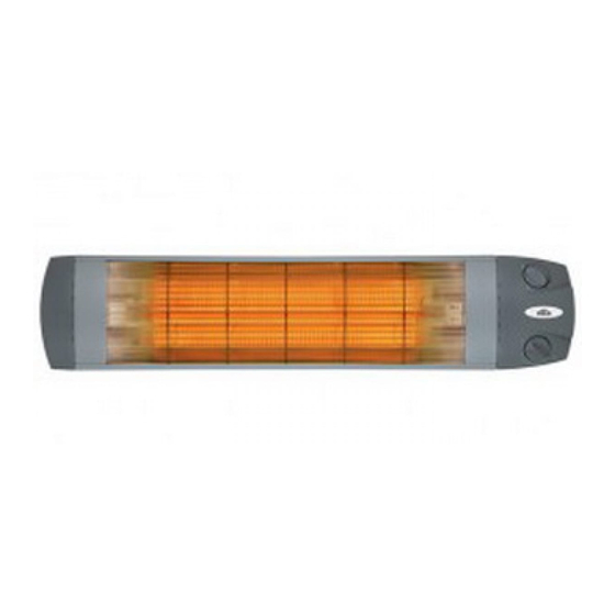
ICW/ICS/ICB Constituent parts Control Output selector Reflector Wide angle 80° Upper element Double on, 50% power IR-carbon- Lower element element on, 50% power Medium wave Both element Ventilating on, 100% power body Front grid metal Thermostat Control room thermostat +5 – +35 °C +/- 1 °C Max thermostat Reflector setting... - Page 8 ICW/ICS/ICB Bracket Rotating to horizontal or vertical position on wall or stand Rip for horizontal Rip for position vertical position Rotating from The heater must Rotating from horizontal to vertical be off and the plug vertical to horizontal position, 90°. pulled from the position, 90°.
- Page 9 ICW/ICS/ICB Mounting Wall or ceiling mounting with the bracket 74 mm ø8 mm Screw DIN 7505 D 5 x 60 Plug D 8 PE 8 x 40 Wall or ceiling mounting with the bracket and aluminium profile ICAP 250 mm After assembly and after the radiation angle is set, tighten the screws.
-
Page 10: Electric Installation
ICW/ICS/ICB Electric installation Cable and plug Cover must be used. ICW/ICS15-20: 3x1,0 mm ICB8-12: 3x1,0 mm ICW/ICS30: 3x1,5 mm Should only be replaced by a qualified electrician. Fixed installation The installation, which should be preceded by an omnipolar switch with a contact separation of at least 3 mm, should only be wired by a competent electrician and in accordance with the latest edition of IEE wiring regulations. - Page 11 ICW/ICS/ICB Minimum mounting distance ICW15-30 och ICS15-30 Wall mounting of ICW15-30 and ICS15-30 ICW/ICS15-20: min 30 cm, Min 10 cm ICW/ICS30: min 50 cm 40 cm Adjustable radiant angle 50 cm min 1,8 m Min 1,8 m from floor Horizontal mounting Vertical mounting Ceiling mounting of ICW15-30 and ICS15-30 Adjustable radiant...
- Page 12 ICW/ICS/ICB Minimum mounting distance ICB8-12 Wall mounting of ICB8-12 Min 10 cm ICB8-12: min 30 cm 40 cm Adjustable radiant angle 30 cm min 0,4 m Min 0,4 m from floor Horizontal mounting Vertical mounting Ceiling mounting of ICB8-12 Adjustable radiant 30 cm angle 30 cm...
- Page 13 ICW/ICS/ICB Maintenance Safety Note! When using for the first time or when • During operation the surfaces of the unit starting up after a long period of disuse, a are hot! small amount of smoke and a slight odour • The unit must not be fully or partially may occur temporarily, which is completely covered with inflammable materials, as normal.
- Page 14 Main offi ce Frico AB Tel: +46 31 336 86 00 Box 102 Fax: +46 31 26 28 25 SE-433 22 Partille mailbox@frico.se Sweden www.frico.se For latest updated information and information about your local contact: www.frico.se...
Need help?
Do you have a question about the ICW Series and is the answer not in the manual?
Questions and answers