Table of Contents
Advertisement
Quick Links
MegaRAID
RAID Controller
Quick Installation Guide
Thank you for purchasing the MegaRAID Serial ATA (SATA)
300-8XLP (PCI-X low profile) RAID controller. Please take a
few minutes to read this quick installation guide before you
install the controller. If you need more information about any
topic covered in this guide, refer to the other documents on
your MegaRAID Universal Software Suite CD.
Note:
The MegaRAID SATA 300-8XLP RAID Controller
supports SATA I and SATA II.
You can use the intelligent Battery Backup Unit 01
(LSIiBBU01) with the MegaRAID SATA 300-8XLP. For more
information about this battery, refer to the MegaRAID Battery
Backup Unit User's Guide on the MegaRAID Universal
Software Suite CD.
M e g a R A I D S A T A 3 0 0 - 8 X L P I N S T A L L A T I O N
Back up your data before you change your
!
system configuration. Otherwise, you might lose
CAUTION
data.
Step 1
Unpack the MegaRAID SATA 300-8XLP RAID
Controller
Unpack the controller in a static-free environment.
Remove it from the antistatic bag and inspect it
for damage.
If the controller appears to be damaged, or if the
MegaRAID Universal Software Suite CD is
missing, contact LSI Logic or your MegaRAID
OEM support representative.
The CD contains utility programs, device drivers
for various operating systems, and the following
documentation:
®
SATA 300-8XLP
• MegaRAID SATA 300 Storage Adapters
User's Guide
• MegaRAID Configuration Software User's
Guide
• MegaRAID Device Driver Installation User's
Guide
• Software license agreement
Step 2
Prepare the Computer
Turn off the computer and unplug the power
cord(s) from the back of the power supply.
Remove the cover from the computer.
Before you install the controller, make sure that
!
the computer is disconnected from the power and
CAUTION
from any networks.
Step 3
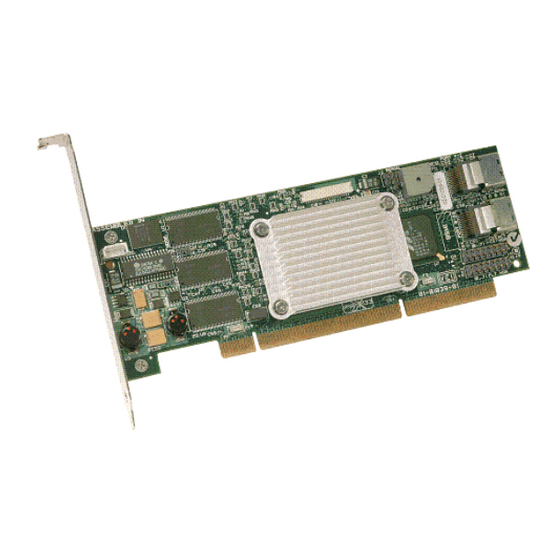
Review the Jumpers and Connectors
Figure 1
shows the location of the jumpers and
the connectors on the MegaRAID SATA
300-8XLP. The jumpers are set at the factory,
and you usually do not need to change them.
Figure 1 MegaRAID SATA 300-8XLP Card Layout
J4
U6
J7
P1
®
J2
J3
J1
Port 4–7
J5
J6
Port 0–3
J8
J9
J10
Advertisement
Table of Contents

Related Manuals for LSI MegaRAID SATA 300-8XLP


Summary of Contents for LSI MegaRAID SATA 300-8XLP
- Page 1 You can use the intelligent Battery Backup Unit 01 Figure 1 MegaRAID SATA 300-8XLP Card Layout (LSIiBBU01) with the MegaRAID SATA 300-8XLP. For more information about this battery, refer to the MegaRAID Battery Backup Unit User’s Guide on the MegaRAID Universal Software Suite CD.
- Page 2 Step 4 Install the MegaRAID SATA 300-8XLP status of this jumper. Insert the MegaRAID SATA 300-8XLP in a PCI-X No jumper: BIOS is enabled. This is slot on the mainboard, as shown in Figure the default.
- Page 3 LSI Logic, the LSI Logic logo design, and MegaRAID are registered trademarks of does the purchase, lease, or use of a product or service from LSI Logic convey a LSI Logic Corporation. All other brand and product names may be trademarks of license under any patent rights, copyrights, trademark rights, or any other of the their respective companies.
Need help?
Do you have a question about the MegaRAID SATA 300-8XLP and is the answer not in the manual?
Questions and answers