Dynojet POWER COMMANDER V Installation Instructions
2009 suzuki ltz400
Hide thumbs
Also See for POWER COMMANDER V:
- Installation instructions and owner's manuals (9 pages) ,
- Installation instructions manual (9 pages) ,
- Installation manual (9 pages)
Advertisement
2009 Suzuki LTZ400
I n s t a l l a t i o n I n s t r u c t i o n s
PLEASE READ ALL DIRECTIONS BEFORE STARTING INSTALLATION
20-002 www.powercommander.com
2191 Mendenhall Drive North Las Vegas, NV 89081 (800) 992-4993 www.powercommander.com
PARTS LIST
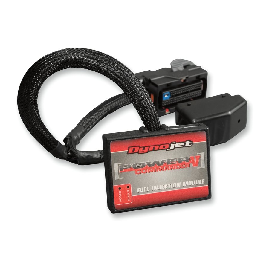
1
Power Commander
1
USB Cable
1
CD-ROM
1
Installation Guide
2
Power Commander Decals
2
Dynojet Decals
THE IGNITION MUST BE TURNED
OFF BEFORE INSTALLATION!
YOU CAN ALSO DOWNLOAD THE
POWER COMMANDER SOFTWARE AND
LATEST MAPS FROM OUR WEB SITE AT:
www.powercommander.com
2009 Suzuki LTZ400 PCV - 1
Advertisement
Table of Contents

Subscribe to Our Youtube Channel
Related Manuals for Dynojet POWER COMMANDER V


Summary of Contents for Dynojet POWER COMMANDER V
- Page 1 I n s t a l l a t i o n I n s t r u c t i o n s Installation Guide Power Commander Decals Dynojet Decals THE IGNITION MUST BE TURNED OFF BEFORE INSTALLATION! YOU CAN ALSO DOWNLOAD THE...
- Page 2 Crank- wire into the hole of the PCV until is stops and then instructed to do so by Dynojet. It is used to tighten the screw. Make sure to reinstall the rubber transfer crank trigger data from one module to plug.
- Page 3 FIG.A Remove the seat and fuel tank. The install can be done without completely removing the fuel tank but the rear of the tank will at least need to be raised up. Lay the PCV unit near the tool kit temporarily and route the harness down the right side of the quad.
- Page 4 FIG.D Locate the Throttle Position Sensor connector (Fig. D). This connector is located on the left side of the throtttle body to the inside of the frame. Follow the TPS harness up to where it meets the main wiring harness. FIG.E Using the supplied Posi-tap connect the GREY wire of the PCV harness to the YELLOW wire...
Need help?
Do you have a question about the POWER COMMANDER V and is the answer not in the manual?
Questions and answers