
Related Manuals for GORMAN-RUPP PUMPS PA4A60-4045T FT4


Summary of Contents for GORMAN-RUPP PUMPS PA4A60-4045T FT4
- Page 1 OM-07165-01 May 1, 2018 INSTALLATION, OPERATION, AND MAINTENANCE MANUAL WITH PARTS LIST PA SERIESr PUMP MODEL PA4A60-4045T FT4 GORMAN‐RUPP PUMPS www.grpumps.com 2015 Gorman‐Rupp Pumps Printed in U.S.A.
- Page 2 Register your new Gorman‐Rupp pump online at www.grpumps.com Valid serial number and e‐mail address required. The engine exhaust from this product contains chemicals known to the State of California to cause cancer, birth defects or other reproductive harm. RECORD YOUR PUMP MODEL AND SERIAL NUMBER Please record your pump model and serial number in the spaces provided below.
-
Page 3: Table Of Contents
TABLE OF CONTENTS INTRODUCTION ..........PAGE I - 1 SAFETY ‐... - Page 4 TABLE OF CONTENTS (continued) Engine Fuel Filter ............PAGE C - 4 Engine Oil .
-
Page 5: Introduction
PA SERIES OM-07165 INTRODUCTION Thank You for purchasing a Gorman‐Rupp pump. HAZARD AND INSTRUCTION Read this manual carefully to learn how to safely DEFINITIONS install and operate your pump. Failure to do so could result in personal injury or damage to the The following are used to alert maintenance per... -
Page 6: Safety - Section A
PA SERIES OM-07165 SAFETY ‐ SECTION A This information applies to Prime Aire the positive battery cable before per Series pumps. Refer to the manual ac forming any maintenance. Failure to do companying the engine or power so may result in serious personal injury. source before attempting to begin oper... - Page 7 OM-07165 PA SERIES certain that the pump and all piping or fingers or tools, causing severe injury to hose connections are tight, properly personnel. supported and secure before operation. Make sure the pump is level. Lower jack Do not operate the pump against a stands and chock the wheels, if so closed discharge valve.
-
Page 8: Installation - Section B
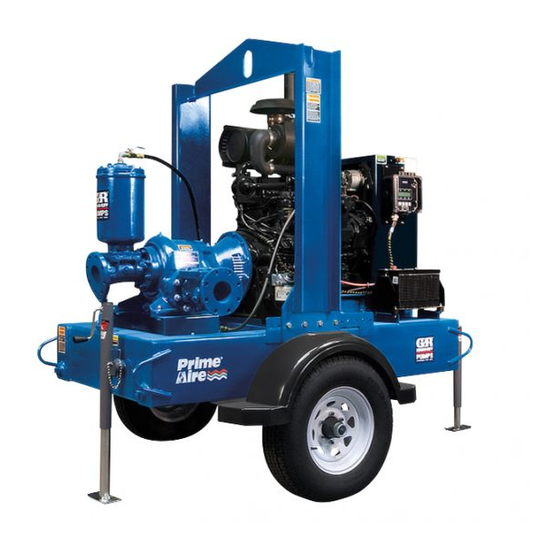
[ 1124,0 ] 23.85 [ 605,7 ] 51.00 [ 1295,4 ] Figure 1. Pump Model PA4A60-4045T FT4 PREINSTALLATION INSPECTION a. Inspect the pump for cracks, dents, damaged threads, and other obvious damage. The pump assembly was inspected and tested be... -
Page 9: Battery Installation
OM-07165 PA SERIES c. Carefully read all tags, decals, and markings POSITIONING PUMP on the pump assembly, and perform all duties indicated. Note that the pump shaft rotates in the required direction. Lifting Only operate this pump in the direction in Death or serious personal injury and dicated by the arrow on the pump body damage to the pump or components... -
Page 10: Suction And Discharge Piping
PA SERIES OM-07165 to secure them when filled with liquid and under pressure. Gauges If the pump has been mounted on a mov able base, do not attempt to operate the The pump is drilled and tapped for installing dis pump unless the unit is level. -
Page 11: Sealing
OM-07165 PA SERIES Sealing air to escape from the liquid before it is drawn into the suction inlet. Since even a slight leak will affect priming, head, If two suction lines are installed in a single sump, and capacity, especially when operating with a the flow paths may interact, reducing the efficiency high suction lift, all connections in the suction line of one or both pumps. -
Page 12: Discharge Lines
PA SERIES OM-07165 Figure 2. Recommended Minimum Suction Line Submergence vs. Velocity DISCHARGE LINES Siphoning If the application involves a high discharge head, gradually close the discharge Do not terminate the discharge line at a level lower than that of the liquid being pumped unless a si throttling valve before stopping the pump. -
Page 13: Float Switch Installation
OM-07165 PA SERIES Float Switch Installation pipe is available, attach the float switch cable to the standpipe in the sump at the approxi mate desired liquid level. The Float Switch autostart system employs either a single or double float switch, where a bulb raises or lowers (floats) with the liquid level, thus activating b. - Page 14 PA SERIES OM-07165 that the liquid in the priming chamber never fully Next, install a drain line between the pump drain freezes. and the wet well or sump. This line must remain submerged in the liquid below the pump down lev The second method involves configuring the el of the liquid level control device;...
-
Page 15: Operation - Section C
OM-07165 PA SERIES OPERATION - SECTION C OPERATION Review all SAFETY information in Section A. Make sure the pump is level. Lower jack Follow the instructions on all tags, labels and stands and chock the wheels, if so decals attached to the pump. equipped. -
Page 16: Operation In Extreme Heat
OM-07165 PA SERIES and fittings tight to maintain maximum pump effi ciency. Pump Vacuum Check Never tamper with the governor to gain more power. The governor establishes Read the vacuum gauge with the pump primed safe operating limits that should not be and at operation speed. -
Page 17: Stopping
OM-07165 PA SERIES vacuum suction gauge readings regularly to detect strainer blockage. Never introduce air or steam pressure into the Never disconnect any of the safety shut pump casing or piping to remove a blockage. This down features; this will void the warran could result in personal injury or damage to the ty and could result in serious damage to equipment. - Page 18 OM-07165 PA SERIES Engine Fuel Filter and priming hopper to prevent damage from freez ing. Also, clean out any solids by flushing with a Consult the manual accompanying the engine, hose. Operate the pump for approximately one and change the fuel filter periodically as indicated. minute;...
- Page 19 OM-07165 PA SERIES TROUBLESHOOTING - SECTION D Review all SAFETY information in Section A. 5. Close the suction and discharge valves. 6. Vent the pump slowly and cau tiously. 7. Drain the pump. Before attempting to open or service the pump: 1.
- Page 20 OM-07165 PA SERIES TROUBLE POSSIBLE CAUSE PROBABLE REMEDY Check strainer and clean if neces Strainer clogged. PUMP STOPS OR FAILS TO DELIVER sary. RATED FLOW OR Check and clean check valve. Discharge check valve clogged. PRESSURE (cont.) Suction intake not submerged at Check installation and correct proper level or sump too small.
- Page 21 OM-07165 PA SERIES TROUBLE POSSIBLE CAUSE PROBABLE REMEDY BEARINGS RUN Bearing temperature is high, but Check bearing temperature regu TOO HOT within limits. larly to monitor any increase. Low or incorrect lubricant. Check for proper type and level of lubricant. Suction and discharge lines not prop...
- Page 22 OM-07165 PA SERIES Preventive Maintenance Schedule Service Interval* Item Daily Weekly Monthly Semi‐ Annually Annually General Condition (Temperature, Unusual Noises or Vibrations, Cracks, Leaks, Loose Hardware, Etc.) Pump Performance (Gauges, Speed, Flow) Bearing Lubrication Seal Lubrication (And Packing Adjustment, If So Equipped) V‐Belts (If So Equipped) Air Release Valve Plunger Rod (If So Equipped) Front Impeller Clearance (Wear Plate)
- Page 23 PUMP MAINTENANCE AND REPAIR - SECTION E MAINTENANCE AND REPAIR OF THE WEARING PARTS OF THE PUMP WILL MAINTAIN PEAK OPERATING PERFORMANCE. STANDARD PERFORMANCE FOR PUMP MODEL PA4A60-4045T FT4 Based on 70 F (21 C) clear water at sea level Contact the Gorman‐Rupp Company to verify per...
- Page 24 OM-07165 PA SERIES PARTS PAGE ILLUSTRATION Figure 1. Pump Model PA4A60-4045T FT4 PAGE E - 2 MAINTENANCE & REPAIR...
- Page 25 OM-07165 PA SERIES Pump Model PA4A60-4045T FT4 PARTS LIST (From S/N 1702446 Up) ITEM PART PART NAME NUMBER PUMP END ASSEMBLY 46133-518 POWER UNIT KIT 46143-206 BATTERY SEE OPTIONS PUMP MOUNTING KIT 48157-107 NOT SHOWN: G‐R DECAL GR-06 PRIME AIRE DECAL...
- Page 26 OM-07165 PA SERIES ILLUSTRATION Figure 2. Power Unit Kit PAGE E - 4 MAINTENANCE & REPAIR...
- Page 27 OM-07165 PA SERIES PARTS LIST Power Unit Kit ITEM PART PART NAME NUMBER BASE/FUEL TANK ASSEMBLY 41553-053 24150 JOHN DEERE 4045T FT4 ENGINE 29224-472 CONTROL PANEL INSTALLATION KIT 48122-563 LIFTING BAIL KIT 48274-811 LOCK WASHER J10 15991 HEX NUT D10 15991 FLAT WASHER K10 15991 HEX HEAD CAP SCREW...
- Page 28 OM-07165 PA SERIES ILLUSTRATION DETAIL A Figure 3. Power Unit Kit (cont'd) PAGE E - 6 MAINTENANCE & REPAIR...
- Page 29 OM-07165 PA SERIES PARTS LIST Power Unit Kit ITEM PART PART NAME NUMBER BASE/FUEL TANK ASSEMBLY 41553-053 24150 JOHN DEERE 4045T FT4 ENGINE 29224-472 CONTROL PANEL INSTALLATION KIT 48122-563 LIFTING BAIL KIT 48274-811 LOCK WASHER J10 15991 HEX NUT D10 15991 FLAT WASHER K10 15991 HEX HEAD CAP SCREW...
- Page 30 OM-07165 PA SERIES ILLUSTRATION Figure 4. Pump End Assembly PAGE E - 8 MAINTENANCE & REPAIR...
- Page 31 OM-07165 PA SERIES Pump End Assembly PARTS LIST ITEM PART PART NAME NUMBER PUMP ASSEMBLY 46133-517 FLANGE GASKET 1676G 18000 STUD C1011 15991 HEX NUT D10 15991 LOCK WASHER J10 15991 SPOOL 38644-802 10000 CHECK VALVE KIT 48274-003 -FLANGE GASKET 25113-034 -CHECK VALVE 26642-124...
- Page 32 OM-07165 PA SERIES ILLUSTRATION Figure 5. Pump Sub Assembly PAGE E - 10 MAINTENANCE & REPAIR...
- Page 33 OM-07165 PA SERIES PARTS LIST Pump Sub Assembly ITEM PART PART NAME NUMBER PUMP CASING SEE NOTE BELOW WEAR PLATE ASSY 10532B 15990 REPAIR ROTATING ASSY 44163-594 LOCK WASHER J06 15991 HEX NUT D06 15991 O‐RING 25154-273 O‐RING S1674 SHIM SET 13130 17040 LOCK WASHER J08 15991...
- Page 34 OM-07165 PA SERIES ILLUSTRATION Figure 6. Repair Rotating Assembly PAGE E - 12 MAINTENANCE & REPAIR...
- Page 35 OM-07165 PA SERIES PARTS LIST Repair Rotating Assembly ITEM PART PART NAME NUMBER IMPELLER 10528 11010 IMP ADJ SHIM SET 37J 17090 CART SEAL ASSY 46513-151 SEAL PLATE 38272-234 10010 GASKET 10959G 20000 OIL SEAL S1352 OIL SEAL S1352 OIL SEAL S1352 LOCK WASHER J08 15991...
- Page 36 OM-07165 PA SERIES ILLUSTRATION Figure 7. Priming Chamber Kit ITEM PART PART NAME NUMBER PRIMING CHAMBER ASSY 46112-709 PIPE BUSHING AP1608 15070 STREET ELBOW RS08 11999 BALL VALVE 26631-052 STUD C0809 15991 HEX NUT D08 15991 LOCK WASHER J08 15991 GASKET 38687-053 19060 BAFFLE...
- Page 37 OM-07165 PA SERIES ILLUSTRATION Figure 8. Priming Chamber Assembly PARTS LIST ITEM PART PART NAME NUMBER PRIMING VALVE 26664-007 -ORIFICE BUTTON 26688-021 HEX HD CAPSCREW B0806 15991 LOCKWASHER J08 15991 PRIMING VALVE GASKET 38683-657 19060 PRIMING CHAMBER 38343-020 10000 STRAINER ASSY 46641-222 17000 INDICATES PARTS RECOMMENDED FOR STOCK MAINTENANCE &...
- Page 38 OM-07165 PA SERIES ILLUSTRATION 0.00 IN. Figure 9. Drive Assembly ITEM PART PART NAME NUMBER COUPLING KIT 48112-005 -BUSHING 24131-496 -COUPLING ASSEMBLY 24391-105 LOCK WASHER 21171-536 SOCKET HEAD CAPSCREW BD0606-1/2 15991 SOCKET HEAD CAPSCREW 22644-220 HEX HD CAPSCREW B0605 15991 HEX HD CAPSCREW 22645-164 HEX HD CAPSCREW...
- Page 39 OM-07165 PA SERIES PUMP AND SEAL DISASSEMBLY any procedures not addressed in this manual are performed only after estab AND REASSEMBLY lishing that neither personal safety nor pump integrity are compromised by Review all SAFETY information in Section A. such practices. Follow the instructions on all tags, label and de...
- Page 40 OM-07165 PA SERIES ot pin. This will allow the linkage to be raised high enough to access the orifice button. Remove the hex nut and lock washer securing the orifice button to the linkage bar and unscrew the Use Only Genuine Gorman-Rupp re orifice button from the linkage bar.
- Page 41 OM-07165 PA SERIES gage the hardware (4 and 5) securing it to the fly Turn wheel. Counterclockwise Remove any leveling shims used under the casing mounting feet. Tie and tag the shims for ease of reassembly. Lathe Dog Arm Move the pump end to a clean, well equipped shop area for further disassembly.
- Page 42 OM-07165 PA SERIES Remove the impeller adjusting shims (2); tie and Disengage the hardware (16 and 17) and remove tag the shims, or measure and record their thick the drive flange (18), gasket (19) and oil seal (6B). ness for ease of reassembly. Press the oil seal from the bearing cap.
- Page 43 OM-07165 PA SERIES tation is rough or the bearing balls are discolored, face is just flush with the counterbored surface to replace the bearings. ward the inside of the bearing housing. Inspect for and remove any sealant shavings that might be re The bearing tolerances provide a tight press fit moved from the O.D.
- Page 44 OM-07165 PA SERIES It is recommended that a sleeve be positioned NOTE against the inboard oil seal to prevent the lip of the The flexible portion of the coupling must be proper oil seal from rolling as the shaft and bearings are ly positioned on the shaft.
- Page 45 OM-07165 PA SERIES tion of the coupling with a non‐petroleum based precautions printed on solvent contain lubricant such as vegetable oil or glycerin, or a sili ers. con‐based lubricant such as “WD40” or equivalent. Clean the seal cavity and shaft with a cloth soaked Do not use petroleum‐based lubricants, or any oth...
- Page 46 OM-07165 PA SERIES NOTE A firm resistance will be felt as the impeller presses the stationary seat into the seal plate bore. This seal is not designed for operation at temperatures above 160 F (71 C). Do not As the stationary seat becomes fully seated, the use at higher operating temperatures.
- Page 47 OM-07165 PA SERIES Handle the seal parts with extreme care to prevent damage. Be careful not to contaminate precision finished faces; even fingerprints on the faces can shorten seal life. If necessary, clean the faces with a The shaft and impeller threads must be non‐oil based solvent and a clean, lint‐free tissue.
- Page 48 OM-07165 PA SERIES ter the impeller scrapes, add approximately .010 linkage bar on the float bottoms against the inch (0,25 mm) of shims to each shim set. threads on the orifice button. When adjustment is complete, install and tighten the lock washer and After the face clearance has been set, tighten the hex nut securing the orifice button.
- Page 49 OM-07165 PA SERIES Under normal conditions, drain the bearing hous ture condensation. This is especially im ing once each year and refill with clean oil. Change portant in areas where variable hot and the oil more frequently if the pump is operated con cold temperatures are common.
- Page 50 For Warranty Information, Please Visit www.grpumps.com/warranty or call: U.S.: 419-755-1280 Canada: 519-631-2870 International: +1-419-755-1352 GORMAN‐RUPP PUMPS...
Need help?
Do you have a question about the PA4A60-4045T FT4 and is the answer not in the manual?
Questions and answers