Table of Contents
Advertisement
Quick Links
Advertisement
Table of Contents

Subscribe to Our Youtube Channel
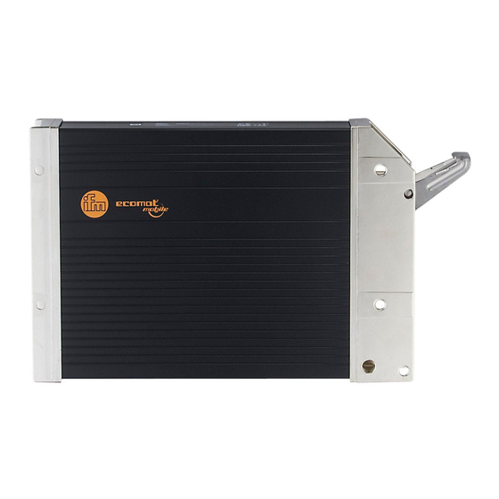
Summary of Contents for IFM Electronic CR0505
- Page 1 Mounting and installation instructions ClassicController R 360 CR0505...
- Page 2 The terminals may only be supplied with the signals indicated in the technical data or on the unit label and only the approved accessories of ifm electronic gmbh may be connected. The unit can be operated within a wide temperature range according to the technical specification indicated below.
-
Page 3: Table Of Contents
(www.ifm.com). ➔ System manual R 360; English (order no. EC2041) Request ➔ Data sheet direct ➔ CR0505 ➔ Additional data Internet The user is responsible for the safe functioning of the application programs which he creates himself. If necessary, he must additionally obtain an approval according to the corresponding national regulations by the corresponding testing and supervisory organisations. - Page 4 CR0505 LASSIC ONTROLLER 3. Installation 3.1 Fastening Fix the controller to a flat surface using 4 M5 screws. ±2 Tightening torque: 8 Use screws with a low head to avoid that the connector is damaged when placed and locked.. Example button head...
-
Page 5: Mounting
CR0505 LASSIC ONTROLLER 3.3 Mounting surface The housing must not be exposed to any torsional forces or mechanical stress. Use compensating elements if there is no flat mounting surface available. 3.4 Heat dissipation Ensure sufficient heat dissipation as the internal heating of the electronics is conducted away via the housing.. -
Page 6: Electrical Connection
CR0505 LASSIC ONTROLLER 4. Electrical connection 4.1 Wiring Wiring see technical data. Only connect the connector pins as shown in the pin layout. Unspecified connector pins remain unconnected.. Connect all supply cables and GND terminals. 4.2 Ground connection To ensure the protection of the device against electrical interference and the safe func- tion of the device, the housing must be connected to the ground of the vehicle. -
Page 7: Maintenance, Repair And Disposal
The disposal must be carried out accord- ing to the corresponding national environmental regulations. 6. Approvals/standards The EC declaration of conformity and approvals can be found at: www.ifm.com ➔ Data sheet search ➔ CR0505 ➔ More information PAGE... -
Page 8: Technical Data (Data Sheets 1
= IEC address for analogue input %IX0.xx = IEC address for binary input %QX0.xx = IEC address for binary output ifm electronic gmbh • Friedrichstraße 1 • 45128 Essen We reserve the right to make technical alterations without prior notice. CR0505 / page 1 18.09.2015... -
Page 9: Operating Status (Status Led)
4 outputs each Physical memory Flash: 2 MByte RAM: 256 kByte Remanent memory: 32 kByte Memory allocation See system manual www.ifm.com → Data sheet search → CR0505 → More information Status indication three-colour LED (R/G/B) Operating states (Status-LED) LED colour Status Description –... -
Page 10: Characteristics Of The Inputs/Outputs
5...25 V; e.g. ifm NAMUR sensors NT5001...NN5002 wiring see page 5 ifm electronic gmbh • Friedrichstraße 1 • 45128 Essen We reserve the right to make technical alterations without prior notice. CR0505 / page 3 18.09.2015... -
Page 11: Wiring
= IEC address for analogue input %IX0.xx = IEC address for binary input %QX0.xx = IEC address for binary output ifm electronic gmbh • Friedrichstraße 1 • 45128 Essen We reserve the right to make technical alterations without prior notice. CR0505 / page 4 18.09.2015... - Page 12 • / – Note the double pin connection of inputs/outputs. *) only positive sensor signals with diagnostic capability ifm electronic gmbh • Friedrichstraße 1 • 45128 Essen We reserve the right to make technical alterations without prior notice. CR0505 / page 5 18.09.2015...


Need help?
Do you have a question about the CR0505 and is the answer not in the manual?
Questions and answers