Advertisement
Quick Links
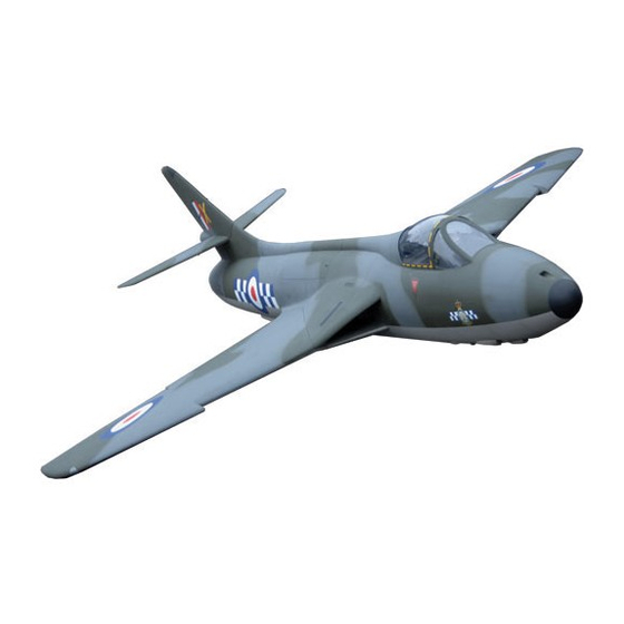
Hawker Hunter
The Flying Legends Hawker Hunter MkVI is a model designed and developed for experienced modellers and pilots.
These instructions are written with the experienced modeller in mind. They are not intended to be a step-by-step guide, but
highlight a few of the areas of construction to supplement your own modelling experience.
Flying Legends Hawker Hunter
Wingspan:
1730mm (68")
Length:
2360mm (93")
Radio:
8 Channel Minimum (8/9 Servos)
Weight:
12-13Kg (26.5 - 28.5Lbs)
Turbine:
80 - 120 Newton Thrust
Instruction Manual
Congratulations on your purchase of the
Flying Legends Hawker Hunter!
241 Green Street,
Enfield,
Middlesex,
EN3 7SJ,
United Kingdom.
Part Number:
Q-FL150
1
Advertisement

Related Manuals for Ripmax Hawker Hunter


Summary of Contents for Ripmax Hawker Hunter
-
Page 1: Instruction Manual
Flying Legends Hawker Hunter! The Flying Legends Hawker Hunter MkVI is a model designed and developed for experienced modellers and pilots. These instructions are written with the experienced modeller in mind. They are not intended to be a step-by-step guide, but highlight a few of the areas of construction to supplement your own modelling experience. -
Page 3: Optional Parts
Based on the original scale outline developed by world famous scale modeller Mick Reeves, the Flying Legends Hawker Hunter Mk IV comprises a fully moulded airframe, which has been completely finished at the factory. Due to this it is vitally important that the components parts are protected during the assembly process to avoid cosmetic damage to the surface finish. - Page 4 Section: Wing Assembly Step 1 Mount the aileron and flap servos to the supplied mounts as shown, ensuring that one pair of servos is opposite handed so as to fit the other wing. Note that servo grommets are not used, as the low vibration level of turbines makes them redundant, and the solid mounting assists precise control.
- Page 5 Step 5 Once the glue has fully cured fit the aileron servo with self tapping screws as shown and make up the pushrod and install. Note that for security the servo extension lead should be taped to the servo lead when they are plugged together. Step 6 Once the aileron servo has been centred and pushrod length adjusted to bring the control surface to neutral the...
- Page 6 Section: Tail Assembly Step 9 Glue the hinges into the rudder and allow to cure, then fit the rudder to the fin, using small pieces of thin plastic around the hinges to avoid gluing the rudder solidly to the fin! The plastic can be torn away once the glue has cured. Use either high quality slow curing epoxy or glue such as Hysol for this highly critical application.
- Page 7 Step 13 Carefully glue the horn into place using Hysol or similar glue for utmost security – masking tape can be used around the mounting to avoid excess glue getting onto the control surface. Once the glue has fully cured make up the pushrod and install as shown.
- Page 8 Section: Fuselage Assembly Step 15 Install your nosewheel steering servo as shown, and fit the steering linkage, ensuring that the nosewheel is perfectly straight with the servo centred. Use a drop of threadlocking compound on the servo mounting screws and fit keepers or short lengths of silicone tubing to the clevises for security.
- Page 9 Step 19 The canopy is supplied with the forward cross brace intact to avoid any chance of distortion during transit – if the optional scale cockpit is to be installed this cross brace needs to be carefully cut away as shown, if the scale cockpit is not being installed then the brace can be left in place as preferred.
- Page 10 Step 23 Fit the fin/rudder, connecting the rudder extension lead to the servo lead at the same time – secure the connection with wrap of tape or similar. Note that the carbon mounting rods fit down through the tailplane and into the mountings in the fuselage.
- Page 11 Step 27 Bolt the front and rear sections of the fuselage together using the four M4 bolts and washers supplied, then run the servo extension leads around the forward fuselage joint former, and then forward to the nose. Install the tailpipe into the fuselage and mount the two front support tabs to either the forward of the two fuselage joint formers if using a Non-Bypass installation, or to the turbine mounts if...
- Page 12 Step 31 To reduce as far as possible the amount of noseweight required we recommend installing all heavy equipment as far forward as is possible. An example of a possible layout is shown, with the ECU and Receiver battery pack being fitted above and below the front part of the forward equipment plate, with retract, door and brake servos and valves just behind, and receiver and sequencer at the rear.
- Page 13 Step 35 Air fill valves, switch and charge socket can be mounted as shown using scraps of ply, and leaving room for the scale cockpit. Step 36 If preferred, the underside bulges, nicknamed “Sabrina’s” can be fitted – these were installed on many Hunters to catch the links when the cannons were fired.
- Page 14 Section: Final Assembly Step 37 With the model completed it is vital to go through thorough checks of every part, as it is all too easy to forget to do up a screw tightly, or neglect to safety wire fuel tubing. Any jet requires very careful assembly and maintenance if it is to be safe and reliable, and the Hunter deserves this care and attention.
- Page 15 Section: Flying the Hawker Hunter Step 40 For first flights we recommend the use of a large and open flying site with a good length of runway, not because the model is hard to fly, but in the event of a minor problem or turbine flameout, having plenty of runway available can make the difference between a safe landing and a wrecked model.
- Page 16 In no case shall Ripmax’s liability exceed the original cost of the purchased kit. In that Ripmax has no control over the final use, no liability shall be assumed or accepted for any damage resulting from the use of the product by the user.
Need help?
Do you have a question about the Hawker Hunter and is the answer not in the manual?
Questions and answers