
Related Manuals for SMA SUNNY BOY3000TL-US


Summary of Contents for SMA SUNNY BOY3000TL-US
- Page 1 PV Inverter SUNNY BOY 3000TL-US / 4000TL-US / 5000TL-US Installation Manual SB3-5TLUS22-IA-en-10 | IA-SB3-5TLUS-22 | Version 1.0...
- Page 3 All such warranties are expressly disclaimed. Neither SMA America, LLC nor its distributors or dealers nor SMA Solar Technology Canada Inc. nor its distributors or dealers shall be liable for any indirect, incidental, or consequential damages under any circumstances.
-
Page 4: Important Safety Instructions
A warning describes a hazard to equipment or personnel. It calls attention to a procedure or practice, which, if not correctly performed or adhered to, could result in damage to or destruction of part or all of the SMA equipment and/or other equipment connected to the SMA equipment or personal injury. Symbol... - Page 5 SMA America, LLC Important Safety Instructions Warnings on this product The following symbols are used as product markings with the following meanings. Symbol Description Warning regarding dangerous voltage The product works with high voltages. All work on the product must only be performed as described in the documentation of the product.
- Page 6 The product contains no user-serviceable parts. For all repair and maintenance, always return the unit to an authorized SMA Service Center. Before installing or using the product, read all of the instructions, cautions, and warnings in this manual.
-
Page 7: Table Of Contents
SMA America, LLC Table of Contents Table of Contents 1 Information on this Document......11 2 Safety . - Page 8 Table of Contents SMA America, LLC 6.2 Overview of the Connection Area ......37 6.2.1 Connection Area of the Inverter.
- Page 9 SMA America, LLC Table of Contents 10.2 Packing the Inverter ........81 10.3 Disposing of the Inverter .
- Page 10 Table of Contents SMA America, LLC SB3-5TLUS22-IA-en-10 Installation Manual...
-
Page 11: Information On This Document
SMA America, LLC 1 Information on this Document 1 Information on this Document Validity This document is valid for the following device types as of firmware version HP V02.05.00.R, KP V02.50.55.R: • Sunny Boy 3000TL-US (SB 3000TL-US-22) • Sunny Boy 4000TL-US (SB 4000TL-US-22) •... - Page 12 1 Information on this Document SMA America, LLC Nomenclature Complete designation Designation in this document PV plant PV Plant SMA America Production, LLC SMA Solar Technology Canada Inc. Sunny Boy Inverter, product Abbreviations Abbreviation Designation Explanation Alternating Current ‒ Direct Current ‒...
-
Page 13: Safety
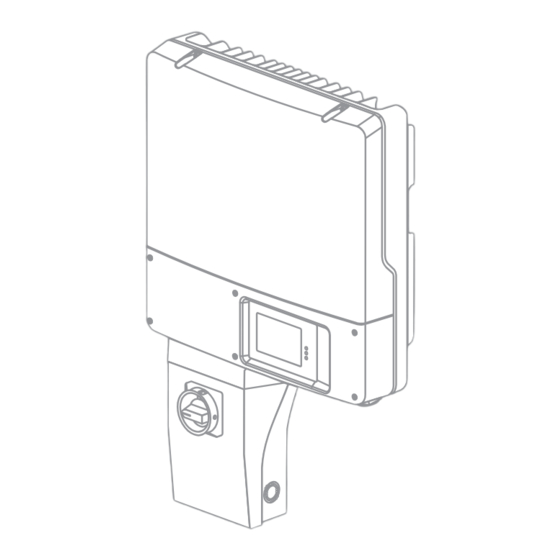
SMA America, LLC 2 Safety 2 Safety 2.1 Intended Use The Sunny Boy is a transformerless PV inverter which converts the direct current of a PV array into grid-compliant alternating current and feeds it into the power distribution grid. Figure 1:... -
Page 14: Skills Of Qualified Persons
1,400 nF. For safety reasons, it is forbidden to modify the product or install components that are not explicitly recommended for this product or distributed by SMA. All components must remain within their permitted operating ranges at all times. -
Page 15: Safety Precautions
SMA America, LLC 2 Safety 2.3 Safety Precautions Danger to life from electric shock due to high voltages in the inverter High voltages that can cause fatal electric shocks are present in the live components of the inverter. • Any work on the inverter must be carried out by qualified persons only. -
Page 16: Scope Of Delivery
3 Scope of Delivery SMA America, LLC 3 Scope of Delivery Check the scope of delivery for completeness and any externally visible damage. Contact your specialty retailer if the scope of delivery is incomplete or damaged. Figure 3: Components included in the scope of delivery... -
Page 17: Product Description
SMA America, LLC 4 Product Description 4 Product Description 4.1 Sunny Boy The Sunny Boy is a transformerless PV inverter which converts the direct current of a PV array into grid-compliant alternating current and feeds it into the power distribution grid. -
Page 18: Symbols On The Inverter
4 Product Description SMA America, LLC The Sunny Boy is a multi-string inverter that has two input areas, A and B, each of which having its own MPP tracker. This permanently determines the maximum power point and controls the voltage on the PV modules accordingly. -
Page 19: Dc Disconnect
SMA America, LLC 4 Product Description 4.2 DC Disconnect The DC Disconnect is a DC switch-disconnector which safely disconnects the PV array from the inverter. Figure 5: DC Disconnect design Item Designation Lug for grounding the DC Disconnect enclosure Enclosure opening... -
Page 20: Type Labels
Device-specific characteristics ‒ You will require the information on the type label to use the inverter safely and when seeking customer support from the SMA Service Line. The type label must be permanently affixed to the inverter. SB3-5TLUS22-IA-en-10 Installation Manual... -
Page 21: Dc Disconnect
DC Disconnect serial number You will require the information on the type label to use the DC Disconnect safely and when seeking customer support from the SMA Service Line. The type label must be permanently affixed to the DC Disconnect. -
Page 22: Symbols On The Type Labels
4 Product Description SMA America, LLC 4.3.3 Symbols on the Type Labels Symbol Designation Explanation Danger to life due to high The product operates at high voltages. voltages All work on the inverter must be carried out by qualified persons only. -
Page 23: Display
SMA America, LLC 4 Product Description 4.4 Display The display shows the current operating data of the inverter (e.g., current power, daily energy, total energy) as well as events or error messages. The power and energy are displayed as bars in the diagram. - Page 24 NetID, the configured country data set and display language. Telephone receiver Indicates a fault that cannot be rectified on site • Contact the SMA Service Line Wrench Indicates a fault that can be rectified on site ® Connection quality...
-
Page 25: Zigbee
SMA inverters and the SolarGuard Gateway. The inverter can therefore transmit data to the SolarGuard gateway, where it can subsequently be read out online via the SolarGuard Internet portal. -
Page 26: Communication Interface
Webconnect function). This communication interface enables the inverter to communicate with special SMA communication products or other inverters (for information on supported products, see www.SMA-Solar.com). The interface can be retrofitted, installed at the factory if specified in the order, or included in the regular scope of delivery. -
Page 27: Sd Card Slot
SMA America, LLC 4 Product Description 4.9 SD Card Slot The inverter is equipped with an SD card slot. You can use the SD card when required to update the inverter firmware. 4.10 Anti-Islanding Protection The inverter has an active safety algorithm to protect against islanding. A stand-alone grid occurs when the power distribution grid is switched off and the inverter attempts to continue to feed in to the power distribution grid. -
Page 28: Mounting
5 Mounting SMA America, LLC 5 Mounting 5.1 Selecting the Mounting Location Requirements for the mounting location: Danger to life due to fire or explosion Despite careful construction, electrical devices can cause fires. • Do not mount the inverter in areas where highly flammable materials are stored. - Page 29 SMA America, LLC 5 Mounting Dimensions for mounting: Figure 9: Wall mounting bracket dimensions Installation Manual SB3-5TLUS22-IA-en-10...
- Page 30 5 Mounting SMA America, LLC Observe recommended clearances: Figure 10: Recommended clearances • Observe recommended clearances to the walls as well as to other inverters or objects. Thus, you will prevent the inverter's power output from being reduced due to excessive temperatures.
-
Page 31: Mounting The Wall Mounting Bracket
SMA America, LLC 5 Mounting Observe permitted mounting position: Figure 11: Permitted and prohibited mounting positions • Mount the inverter in a permitted mounting position with the display at eye level. This ensures that there can be no ingress of moisture into the inverter and you can read out display messages and LED signals without any difficulty. - Page 32 5 Mounting SMA America, LLC 1. Screw the DC Disconnect retainer onto the inverter wall mounting bracket using the screws and washers supplied. In doing so, tighten the two upper screws (M5x12) from the rear and the lower (M5x8) from the front.
-
Page 33: Mounting The Inverter And Dc Disconnect
SMA America, LLC 5 Mounting 5.3 Mounting the Inverter and DC Disconnect Risk of injury when lifting and from the inverter falling The inverter is heavy (see Section 11 "Technical Data", page 82). Risk of injury exists through incorrect lifting and through the inverter falling during transport or when hanging in the wall mounting bracket. - Page 34 5 Mounting SMA America, LLC 6. Place the DC Disconnect into the retainer from the front. In doing so, lead the lug over the ridge in the Position the DC Disconnect inverter. 7. Attach the DC Disconnect with anchorage bracket...
-
Page 35: Attaching The Anti-Theft Device
SMA America, LLC 5 Mounting 5.4 Attaching the Anti-Theft Device You can protect the inverter from theft with a padlock. The padlock locks the inverter to the wall mounting bracket. The padlock must meet the following requirements: ☐ The material must be rust-proof. -
Page 36: Electrical Connection
6 Electrical Connection SMA America, LLC 6 Electrical Connection 6.1 Safety during Electrical Connection Danger to life from electric shock due to high voltages High voltages are present in the DC cables and later during operations in the conductive components of the inverter. These can cause fatal electric shocks. -
Page 37: Overview Of The Connection Area
SMA America, LLC 6 Electrical Connection 6.2 Overview of the Connection Area 6.2.1 Connection Area of the Inverter Figure 13: Connection area inside the inverter Item Designation Explanation Cable gland For leading the connection cable between the DC Disconnect and inverter... -
Page 38: Connection Area Of The Dc Disconnect
6 Electrical Connection SMA America, LLC Item Designation Explanation Enclosure opening ( ⁄ in. (19 mm)) For the conduit fitting used to insert the optional connecting cable of an emergency power module Enclosure opening For the cable gland used to insert the optional... -
Page 39: Ac Connection
SMA America, LLC 6 Electrical Connection Item Designation Explanation Screw terminals For the connection of the PV strings (input A+) Screw terminals For the connection of the PV strings (input B‒) Screw terminals For the connection of the PV strings (input A‒) 6.3 AC Connection... -
Page 40: Connecting The Inverter To The Power Distribution Grid
6 Electrical Connection SMA America, LLC Switch-disconnector and cable protection: Damage to the inverter by using screw-type fuses as switch-disconnectors Screw-type fuses do not have load disconnection properties and may damage the inverter if disconnected under load. • Do not use screw-type fuses as switch-disconnectors. - Page 41 SMA America, LLC 6 Electrical Connection 6. Lead the conduit with the AC cables through the enclosure opening into the inverter and screw the conduit fitting tight. 7. Strip the insulation of L1, L2, N and the equipment grounding conductor each by in.
- Page 42 6 Electrical Connection SMA America, LLC 10. Ensure that the conductors are securely in place in the terminals. 11. Move the clamping bracket over the protective ground conductor, positioning the protective ground conductor on the left as you do so.
-
Page 43: Dc Connection
SMA America, LLC 6 Electrical Connection 6.4 DC Connection 6.4.1 Safety During DC Connection Danger to life due to high voltages on DC conductors Risk of death or serious injury due to electric shock from touching a DC conductor. • Do not touch the DC conductors. -
Page 44: Connecting The Pv Array
6 Electrical Connection SMA America, LLC Additionally required mounting material (not included in the scope of delivery): ☐ Number of rainproof or waterproof conduit fittings required ( ⁄ in. (19 mm)) ☐ Number of rigid conduits required ( ⁄ in. (19 mm)) ☐... - Page 45 SMA America, LLC 6 Electrical Connection Damage to the DC Disconnect due to enlarged knockout holes Enlarged knockout holes enable moisture to penetrate the DC Disconnect which could damage electronic components in the DC Disconnect. • Do not enlarge the knockout holes.
- Page 46 6 Electrical Connection SMA America, LLC 11. Check the PV array for ground faults (see Section 9.5 "Checking the PV Plant for a Ground Fault", page 76). 12. Connect the first string to the terminal blocks for input A: • Connect the DC+ cable to the screw terminal + (torque: 15 in-lb (1.7 Nm)).
- Page 47 SMA America, LLC 6 Electrical Connection 18. Screw the DC Disconnect lid into place (torque: 44 in-lb. (5 Nm)). Closing the DC Disconnect 19. Screw the DC Disconnect rotary switch onto the lid hand-tight. Rotary switch in position Installation Manual...
-
Page 48: Connecting The Emergency Power Module
6 Electrical Connection SMA America, LLC 6.5 Connecting the Emergency Power Module Connection principle Additionally required mounting material (not included in the scope of delivery): ☐ Switch to activate the emergency power socket-outlet designed for at least 120 V (AC) and 10 A ☐... - Page 49 SMA America, LLC 6 Electrical Connection 1. When the inverter is in operation, disconnect it (see Section 8). 2. Loosen the screw on the display and flip the display up until it clicks into place. Do not kink the adjacent cable when doing so.
- Page 50 6 Electrical Connection SMA America, LLC 8. Connect the grounding cable to the same terminal as the protective grounding conductor from the inverter. 9. Secure the conduit fitting from the inside using the counter nut. 10. Connect the insulated conductors that are connected to the gray terminals on the emergency power module to the socket-outlet.
-
Page 51: Connecting The Zigbee ® Antenna
SMA America, LLC 6 Electrical Connection ® 6.6 Connecting the Zigbee Antenna • Turn the antenna into the screw connection on the inverter hand-tight. Installation Manual SB3-5TLUS22-IA-en-10... -
Page 52: Commissioning
7 Commissioning SMA America, LLC 7 Commissioning 7.1 Making Settings via the Rotary Switches 7.1.1 Overview of the Rotary Switches The inverter can be configured for different countries and for use in backup and off-grid systems via 2 rotary switches. The rotary switches can also be used to change the display language. - Page 53 SMA America, LLC 7 Commissioning Possible settings of the rotary switches Here, you will find a list of possible rotary switch positions and which country data sets and display languages are behind each position. Each country data set contains various operating parameters, which can be individually set according to each country data set.
-
Page 54: Changing The Country Data Set And The Display Language
* The country data set is automatically blocked after 10 feed-in hours. You can then only change the country data set by inputting the personal access code you received from SMA on a communication device. 7.1.2 Changing the Country Data Set and the Display Language If the default country data set of the inverter does not apply to your country, then you must change the country data set and the display language. -
Page 55: Changing The Display Language
SMA America, LLC 7 Commissioning 7.1.3 Changing the Display Language You can change the display language independently of the country data set. This ensures that the country data set remains unchanged. Hint: If you simply remove the jumper, the display language automatically changes to English. -
Page 56: Commissioning The Inverter
7 Commissioning SMA America, LLC 7.2 Commissioning the Inverter Requirements: ☐ The AC miniature circuit-breaker must be correctly rated. ☐ The inverter must be correctly mounted and closed. ☐ The DC Disconnect must be correctly mounted and closed. ☐ All cables must be correctly connected. -
Page 57: Changing The Country Data Set Using A Communication Product
☐ The responsible grid operator must approve changes of grid-relevant parameters. ☐ An SMA Grid Guard code for changing the grid-relevant parameters must be available (for application for the SMA Grid Guard code, see certificate "Application for a Personal Access Code"... -
Page 58: Disconnecting The Inverter From Voltage Sources
8 Disconnecting the Inverter from Voltage Sources SMA America, LLC 8 Disconnecting the Inverter from Voltage Sources Danger to life due to high voltages in the inverter Death or serious injury due to electric shock • Only open the inverter in the order described here. - Page 59 SMA America, LLC 8 Disconnecting the Inverter from Voltage Sources • Ensure that no voltage is present between L 1 and N. • Ensure that no voltage is present between L 1 and the equipment grounding conductor. • Ensure that no voltage is present between L2 and N.
-
Page 60: Disconnecting The Dc Disconnect From Voltage Sources
8 Disconnecting the Inverter from Voltage Sources SMA America, LLC 8.1 Disconnecting the DC Disconnect from Voltage Sources 1. Turn the rotary switch of the DC Disconnect to Off. 2. Wait until the LEDs and the display have gone out. -
Page 61: Troubleshooting
SMA America, LLC 9 Troubleshooting 9 Troubleshooting 9.1 LED Signals The LEDs indicate the operating state of the inverter. Status Explanation Green Is lit Operation If an event occurs, the event message is shown in the display (see Section 9.2). -
Page 62: Event Messages
The AFCI self-test was successful The inverter has successfully performed the electric arc detection self-test. Grid Guard code valid The SMA Grid Guard code entered is valid. Protected parameters have now been unblocked and you can adjust the parameters. The parameters will be automatically locked again after 10 feed-in hours. -
Page 63: Error Messages
If the line voltage is permanently in the permissible range and this message is still displayed, contact the SMA Service Line. Installation Manual SB3-5TLUS22-IA-en-10... - Page 64 If the line voltage is permanently in the permissible range and this message is still displayed, contact the SMA Service Line. SB3-5TLUS22-IA-en-10 Installation Manual...
- Page 65 If the line voltage is permanently in the permissible range and this message is still displayed, contact the SMA Service Line. 401 to 404 Grid fault The inverter is no longer in grid-parallel operation.
- Page 66 If the grid operator approves, discuss any changes to the operating parameters with the SMA Service Line. Waiting for grid There is no line voltage at the inverter's AC voltage output.
- Page 67 • If the DC voltage is above the maximum input voltage of the inverter, ensure that the PV array has been correctly rated or contact the PV array installer. • If this message is repeated frequently, contact the SMA Service Line. Installation Manual SB3-5TLUS22-IA-en-10...
- Page 68 9 Troubleshooting SMA America, LLC Event number Display message Cause and corrective measures 3501 Insulation resist. The inverter has detected a ground fault in the PV array. Check generator Corrective measures: • Check the PV plant for ground faults (see Section 9.5).
- Page 69 6001 to 6009 Self diagnosis The cause must be determined by the SMA Service Line. Interference device Corrective measures: • Contact the SMA Service Line. 6101 to 6112 Self diagnosis The cause must be determined by the SMA Service Line. Interference device Corrective measures: •...
- Page 70 Self diagnosis The cause must be determined by the SMA Service Line. Overload Corrective measures: • Contact the SMA Service Line. 6701 to 6702 Comm. disturbed A fault has occurred in the internal communication of the inverter. The inverter continues feeding power into the grid.
- Page 71 Parameters cannot be set via the SD card. The failed inverter continues feeding power into the grid. Corrective measures: • Check the parameters for valid values. • Ensure change rights via SMA Grid Guard code. 7106 Update file defective The update file is defective. The update failed.
- Page 72 Corrective measures: • Clean the fans • Replace the fans. 7701 to 7712 Self diagnosis The cause must be determined by the SMA Service Line. Interference device Corrective measures: • Contact the SMA Service Line. SB3-5TLUS22-IA-en-10 Installation Manual...
- Page 73 8101 to 8104 Comm. disturbed The cause must be determined by the SMA Service Line. Corrective measures: • Contact the SMA Service Line. 8204 AFCI self-test failed The cause must be determined by the SMA Service Line. Corrective measures: •...
- Page 74 ‒25°C. • If the ambient temperature is above ‒25°C, contact the SMA Service Line. 9002 Grid Guard code The SMA Grid Guard code entered is incorrect. invalid The parameters are still protected and cannot be changed. Corrective measures: • Enter the correct SMA Grid Guard code.
- Page 75 • Check setting of the rotary switches(see Section 7.1.2 "Changing the Country Data Set and the Display Language", page 54). • Enter the SMA Grid Guard code. • Ensure that sufficient DC voltage is available (green LED lit or flashing). Installation Manual...
-
Page 76: Cleaning The Inverter
9 Troubleshooting SMA America, LLC 9.4 Cleaning the Inverter • Damage to the display due to the use of cleaning agents • If the inverter is dirty, clean the enclosure lid, the display, and the LEDs using only clean water and a cloth. - Page 77 The example shows a ground fault between the second and third PV modules. 4. Eliminate the ground fault. 5. Commission the inverter (see Section 7.2). 6. If there is no ground fault and the message continues to be displayed, contact the SMA Service Line. Installation Manual...
-
Page 78: Replacing Dc Varistors
In regions where storms or other DC overvoltages frequently occur, the DC varistors lose their functionality if the PV plant is not equipped with additional overvoltage protection. In such cases, SMA recommends replacing DC varistors with new ones after an operating period of 10 years in order to ensure that the functionality of the DC varistors remains at a constant level. - Page 79 SMA America, LLC 9 Troubleshooting 5. Ensure that the wires of the varistors are secure in the terminal. 6. Remove the insertion tool from the contacts of the terminal block. 7. Push the DC Disconnect lid diagonally under the upper edge of the enclosure and press the lid Closing the DC Disconnect down.
-
Page 80: Decommissioning
10 Decommissioning SMA America, LLC 10 Decommissioning 10.1 Disassembling the Inverter 1. Disconnect the inverter and the DC-Disconnect (see Section 8). 2. Remove the AC cable from the inverter. 3. If the emergency power module is connected, remove the cable from the inverter. -
Page 81: Packing The Inverter
• Dispose of the inverter in accordance with the locally applicable disposal regulations for electronic waste. Return the inverter to SMA at your own expense (see Section 14 "Contact", page 91). When doing so, label the packaging with the information "FOR DISPOSAL". -
Page 82: Technical Data
11 Technical Data SMA America, LLC 11 Technical Data 11.1 DC/AC 11.1.1 Sunny Boy 3000TL-US DC Input Maximum DC power at cos φ = 1 3,200 W Maximum input voltage 600 V MPP voltage range 175 V to 480 V... -
Page 83: Sunny Boy 4000Tl-Us
SMA America, LLC 11 Technical Data Efficiency Maximum efficiency, η 97.1% CEC efficiency, η 97.0% 11.1.2 Sunny Boy 4000TL-US DC Input Maximum DC power at cos φ = 1 4,200 W Maximum input voltage 600 V MPP voltage range 175 V to 480 V... -
Page 84: Sunny Boy 5000Tl-Us
11 Technical Data SMA America, LLC Efficiency Maximum efficiency, η 97.2% CEC efficiency, η 97.0% 11.1.3 Sunny Boy 5000TL-US DC Input Maximum DC power at cos φ = 1 5,300 W Maximum input voltage 600 V MPP voltage range 175 V to 480 V... -
Page 85: General Data
SMA America, LLC 11 Technical Data Feed-in phases Connection phases Efficiency Maximum efficiency, η 97.1% CEC efficiency, η 97.0% 11.2 General Data Width x height x depth, inverter in. x 20 in. x 7 (490 mm x 519 mm x 185 mm) Width x height x depth, DC-Disconnect in. -
Page 86: Protective Devices
DC disconnection device DC Disconnect DC overvoltage protection Varistors AC short-circuit current capability Current control Grid monitoring SMA Grid Guard X Maximum permissible fuse protection 30 A Ground-fault monitoring Insulation monitoring: R ≥ 600 kΩ All-pole sensitive residual-current monitoring unit... -
Page 87: Features
SMA America, LLC 11 Technical Data 11.6 Features DC connection Screw terminal AC connection Spring clamp terminal Display LC graphic display ® Zigbee optional RS485, galvanically isolated optional Fan retrofit kit optional Emergency Power Module optional* * only available ex-works 11.7 DC Disconnect... -
Page 88: Grounding Systems
11 Technical Data SMA America, LLC 11.9 Grounding Systems 208 Delta: 120 WYE Suitable 240: 120 Split Phase Suitable 11.10 Data Storage Capacity Daily energy yield 63 days Daily yields 30 years Event messages for users 250 events Event messages for installers... -
Page 89: Accessories
SMA America, LLC 12 Accessories 12 Accessories You will find relevant accessories and spare parts for your product in the following overview. If needed, you can order these from SMA or your specialty retailer. Designation Brief Description SMA order number DC replacement varistors Set with 4 varistors incl. -
Page 90: Compliance Information
• Connect the equipment into an outlet on a circuit different from that to which the receiver is connected. • Consult the dealer or an experienced radio/TV technician for help. • The user is cautioned that changes or modifications not expressly approved by SMA America, Inc. could void the user’s authority to operate this equipment. IC Compliance This device complies with Industry of Canada licence-exempt RSS standard(s) and contains Model XBee Radio, IC: 9440B-SCOM31. -
Page 91: Contact
SMA America, LLC 14 Contact 14 Contact If you have technical problems concerning our products, contact the SMA Service Line. We need the following data in order to provide you with the necessary assistance: • Inverter device type • Inverter serial number •... - Page 92 SMA Solar Technology www.SMA-Solar.com SMA America, LLC www.SMA-America.com...
Need help?
Do you have a question about the SUNNY BOY3000TL-US and is the answer not in the manual?
Questions and answers
My Sunny Boy 3000TL-US inverter has an 801 error code that the "fuse" may need to be replaced. I cannot locate the fuse. Please advise. THANKS!