
Related Manuals for Cypress Semiconductor CY8CKIT-062S2-43012


Summary of Contents for Cypress Semiconductor CY8CKIT-062S2-43012
- Page 1 CY8CKIT-062S2-43012 PSoC 62S2 Wi-Fi BT Pioneer Kit Guide Doc. # 002-28109 Rev. *E Cypress Semiconductor 198 Champion Court San Jose, CA 95134-1709 www.cypress.com...
- Page 2 Copyrights Copyrights © Cypress Semiconductor Corporation, 2019–2020. This document is the property of Cypress Semiconductor Corporation and its subsidiaries (“Cypress”). This document, including any software or firmware included or referenced in this document (“Software”), is owned by Cypress under the intellectual property laws and treaties of the United States and other countries worldwide.
-
Page 3: Table Of Contents
3.3.2 ETM Trace Header..................46 3.3.3 microSD Card Detect Multiplexing ..............46 3.3.4 microSD Card SPI Multiplexing..............47 3.3.5 U.FL (UMCC) Connector for External Antenna ..........47 3.3.6 U.FL (UMCC) Connector for Antenna Diversity..........47 CY8CKIT-062S2-43012 PSoC 62S2 Wi-Fi BT Pioneer Kit Guide, Doc. # 002-28109 Rev. *E... - Page 4 Contents Bill of Materials ......................48 Frequently Asked Questions..................48 Revision History CY8CKIT-062S2-43012 PSoC 62S2 Wi-Fi BT Pioneer Kit Guide, Doc. # 002-28109 Rev. *E...
-
Page 5: Safety And Regulatory Compliance Information
Contact support@cypress.com for details. The CY8CKIT-062S2-43012, as shipped from the factory, has been verified to meet with the requirements of CE as a Class A product. PSoC 62S2 Wi-Fi BT Pioneer Boards contain electrostatic discharge (ESD)- sensitive devices. - Page 6 Handling Boards CY8CKIT-062S2-43012 PSoC 62S2 Wi-Fi BT Pioneer Kit is sensitive to ESD. Hold the board only by its edges. After removing the board from its box, place it on a grounded, static-free surface. Use a conductive foam pad, if available.
- Page 7 Regulatory Statements and Product Labeling United States (FCC) The CY8CKIT-062S2-43012 contains Type1LV modular transmitter that complies with Part 15 of the Federal Communications Commission (FCC) Rules. The FCC ID for this device is VPYLBEE59B1LV. Operation is subject to the following two conditions: This device may not cause harmful interference ■...
-
Page 8: Introduction
Introduction Thank you for your interest in the CY8CKIT-062S2-43012 PSoC 62S2 Wi-Fi BT Pioneer Kit. The PSoC 62S2 Wi-Fi BT Pioneer Kit enables you to evaluate and develop your applications using the PSoC 62 Series MCU (hereafter called “PSoC 6 MCU”) and CYW43012 WICED Wi-Fi/BT combo device. -
Page 9: Kit Contents
Introduction Kit Contents The CY8CKIT-062S2-43012 PSoC 62S2 Wi-Fi BT Pioneer Kit has the following contents, as shown Figure 1-1. PSoC 62S2 Wi-Fi BT Pioneer Board ■ USB Type-A to Micro-B cable ■ Four jumper wires (4 inches each) ■ Two jumper wires (5 inches each) ■... -
Page 10: Getting Started
Two user LEDs, an RGB LED, two user buttons, and a reset button for PSoC 6 MCU ■ A potentiometer ■ One Mode selection button and one Status LED for KitProg3 ■ A microSD Card holder ■ CY8CKIT-062S2-43012 PSoC 62S2 Wi-Fi BT Pioneer Kit Guide, Doc. # 002-28109 Rev. *E... - Page 11 IO1 (J22.2) P0[4] User button with GPIO on non-Arduino – Hibernate wakeup header (J21.9) capability P0[5] RGB green LED GPIO on non-Arduino – (LED5) header (J24.3) CY8CKIT-062S2-43012 PSoC 62S2 Wi-Fi BT Pioneer Kit Guide, Doc. # 002-28109 Rev. *E...
- Page 12 TCK/SWD SWCLK P7[0] ETM Clock – – P7[1] CapSense CINTA – – P7[2] CapSense CINTB – – P7[3] RGB blue LED GPIO on non-Arduino – (LED5) header (J24.5) CY8CKIT-062S2-43012 PSoC 62S2 Wi-Fi BT Pioneer Kit Guide, Doc. # 002-28109 Rev. *E...
- Page 13 Populate R127 to connect to ETM Trace header. P9[2] Extended Arduino ETM TRACEDATA[1] Remove R123 to disconnect from J2 A10 (J2.6) header. Populate R128 to connect to ETM Trace header. CY8CKIT-062S2-43012 PSoC 62S2 Wi-Fi BT Pioneer Kit Guide, Doc. # 002-28109 Rev. *E...
- Page 14 P12[5] microSD card CLK – Remove R166 to disconnect from microSD card connector. P12[6] ECO Crystal XIN – – P12[7] ECO Crystal XOUT – – CY8CKIT-062S2-43012 PSoC 62S2 Wi-Fi BT Pioneer Kit Guide, Doc. # 002-28109 Rev. *E...
- Page 15 I2S serial data out – – BT_I2S_DI I2S serial data in – – BT_IO_2 Bluetooth general- – – purpose I/Os BT_IO_3 Bluetooth general- – – purpose I/Os CY8CKIT-062S2-43012 PSoC 62S2 Wi-Fi BT Pioneer Kit Guide, Doc. # 002-28109 Rev. *E...
-
Page 16: Additional Learning Resources
Click the File icon and then click Open. Times New Roman Displays an equation: 2 + 2 = 4 Text in gray boxes Describes cautions or unique functionality of the product. CY8CKIT-062S2-43012 PSoC 62S2 Wi-Fi BT Pioneer Kit Guide, Doc. # 002-28109 Rev. *E... -
Page 17: Acronyms
Quad Serial Peripheral Interface Successive Approximation Register SDHC Secure Digital Host Controller SDIO Secure Digital Input Output SMIF Serial Memory Interface Serial Peripheral Interface SRAM Serial Random Access Memory CY8CKIT-062S2-43012 PSoC 62S2 Wi-Fi BT Pioneer Kit Guide, Doc. # 002-28109 Rev. *E... - Page 18 Introduction Table 1-3. Acronyms Used in this Document (continued) Acronym Definition Serial Wire Debug UART Universal Asynchronous Receiver Transmitter Universal Serial Bus Watch Crystal Oscillator CY8CKIT-062S2-43012 PSoC 62S2 Wi-Fi BT Pioneer Kit Guide, Doc. # 002-28109 Rev. *E...
-
Page 19: Kit Operation
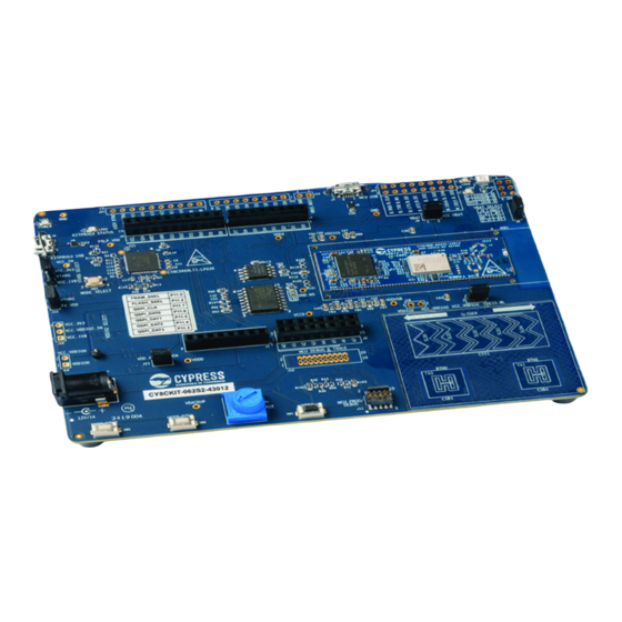
BREG Power Modes High Speed I/O Matrix, Smart I/O, Boundary Scan Active/Sleep 2x Smart IO LowePowerActive/Sleep DeepSleep 98x GPIO Enh, 6x GPIO OVT Hibernate IO Subsystem Backup CY8CKIT-062S2-43012 PSoC 62S2 Wi-Fi BT Pioneer Kit Guide, Doc. # 002-28109 Rev. *E... - Page 20 The PSoC 62S2 Wi-Fi BT Pioneer Kit comes with the PSoC 62S2 Wi-Fi BT Pioneer Board. Figure 2-3 Figure 2-4 show the markup of the Pioneer Board. Figure 2-3. PSoC 62S2 Wi-Fi BT Pioneer Board - Top View 33 16 15 16 CY8CKIT-062S2-43012 PSoC 62S2 Wi-Fi BT Pioneer Kit Guide, Doc. # 002-28109 Rev. *E...
- Page 21 These buttons also provides a wake-up source from low-power modes of the device. In addition, this button can be used to activate the regulator control output from PSoC 6 MCU. CY8CKIT-062S2-43012 PSoC 62S2 Wi-Fi BT Pioneer Kit Guide, Doc. # 002-28109 Rev. *E...
- Page 22 CYW43012 VBAT power domain. 27. CYW43012 VBAT power selection jumper (J9): This jumper is used to select the CYW43012 VBAT supply voltage between 1.8 V, 3.3 V and 3.6 V. CY8CKIT-062S2-43012 PSoC 62S2 Wi-Fi BT Pioneer Kit Guide, Doc. # 002-28109 Rev. *E...
- Page 23 36. microSD Card holder (J20): Provide SDHC interface with microSD cards with the option to detect the presence of the card. Hardware Functional Description on page 30 for details on various hardware blocks. CY8CKIT-062S2-43012 PSoC 62S2 Wi-Fi BT Pioneer Kit Guide, Doc. # 002-28109 Rev. *E...
-
Page 24: Kitprog3: On-Board Programmer/Debugger
2. In the ModusToolbox IDE, import the desired code example (application) into a new workspace. a. Click on New Application from Quick Panel. Figure 2-6. Create New Application CY8CKIT-062S2-43012 PSoC 62S2 Wi-Fi BT Pioneer Kit Guide, Doc. # 002-28109 Rev. *E... - Page 25 Kit Operation b. Select the CY8CKIT-062S2-43012 in the Choose Hardware Target window and click Next, as shown in Figure 2-7. Figure 2-7. New Application Creation: Choose Target Hardware c. Select the application in Starter Application window and click Next, as shown in Figure 2-8.
- Page 26 <App_Name> Debug (KitProg3) configuration as shown in Figure 2-11. For a detailed explanation on how to debug using ModusToolbox, see KBA224621. Figure 2-11. Debugging in ModusToolbox CY8CKIT-062S2-43012 PSoC 62S2 Wi-Fi BT Pioneer Kit Guide, Doc. # 002-28109 Rev. *E...
- Page 27 6. Press the Enter key again. Confirm that the kit LED resumes blinking at 1 Hz. The message displayed on the terminal is updated to “LED blinking resumed”. You can repeat steps 5 and 6 indefinitely. CY8CKIT-062S2-43012 PSoC 62S2 Wi-Fi BT Pioneer Kit Guide, Doc. # 002-28109 Rev. *E...
-
Page 28: Usb-Uart Bridge
Figure 2-14 shows. Figure 2-14. UART Connection between KitProg3 and CYW43012 For more details on the KitProg3 USB-UART functionality, see the KitProg3 User Guide. CY8CKIT-062S2-43012 PSoC 62S2 Wi-Fi BT Pioneer Kit Guide, Doc. # 002-28109 Rev. *E... -
Page 29: Usb-I2C Bridge
KitProg3 USB-I2C functionality, see the KitProg3 User Guide. Figure 2-15. I2C Connection between KitProg3 and PSoC 6 MCU P6_VDD KitProg3 PSoC 6 MCU R133 R134 4.7K 4.7K KP_I2C_SDA P6[1] KP_I2C_SCL P6[0] CY8CKIT-062S2-43012 PSoC 62S2 Wi-Fi BT Pioneer Kit Guide, Doc. # 002-28109 Rev. *E... -
Page 30: Hardware
VDDIO0 VREF VDDIO0 VDDIO2 6.3V VCCD VDDIO2 VCCD VDD_NS VDD_NS 6.3V VDDUSB VSS0 VDDUSB VSS1 VSS2 VBACKUP VBUCK VCCD VSS3 VSS4 VBACKUP VSS5 0 OHM CY 8C624ABZI-S2D44 CY8CKIT-062S2-43012 PSoC 62S2 Wi-Fi BT Pioneer Kit Guide, Doc. # 002-28109 Rev. *E... - Page 31 Decoupling Capacitors VDDD VDDIO0 VDDIO1 VDDIO2 VBACKUP 10uF 0.1uF 0.1uF 0.1uF 0.1uF 0.1uF 6.3V 6.3V 6.3V 6.3V VDDA VDDUSB VDD_NS 10uF 0.1uF 0.1uF 0.1uF 10uF 0.1uF 6.3V 6.3V CY8CKIT-062S2-43012 PSoC 62S2 Wi-Fi BT Pioneer Kit Guide, Doc. # 002-28109 Rev. *E...
- Page 32 GND72 VDDOUT_VDDIO GND73 GND94 VOUT_3P3 GND95 GND96 VOUT_3P3 GND97 GND98 GND1 GND99 GND2 GND100 GND3 GND101 GND6 GND102 GND11 GND103 GND15 GND104 GND19 GND105 GND20 GND106 LBEE59B1LV CY8CKIT-062S2-43012 PSoC 62S2 Wi-Fi BT Pioneer Kit Guide, Doc. # 002-28109 Rev. *E...
- Page 33 Make sure NO stub for SDIO_CMD net 6.3V SIT1533AI-H4-DCC-32.768E 32.768KHz Antenna Diversity Switch VOUT_3P3 0.1uF ANT0 8.2pF OUT1 RF_SW_IN ANT1_ANT2 OUT2 A-1JB RF_SW_CTRL_8 VCTL RTC7608 8.2pF SON6H_0.35mm CY8CKIT-062S2-43012 PSoC 62S2 Wi-Fi BT Pioneer Kit Guide, Doc. # 002-28109 Rev. *E...
- Page 34 WL_IO_2 BT_IO_2 BT_GPIO_3 BT_IO_3 WL_JTAG_TCK BT_GPIO_4 WL_JTAG_TCK BT_IO_4 WL_JTAG_TMS BT_GPIO_5 WL_JTAG_TMS BT_IO_5 WL_JTAG_TRST_L WL_JTAG_TRST_L WL_JTAG_TDI WL_JTAG_TDI RFU_1 WL_JTAG_TDO WL_JTAG_TDO RFU_2 WL_JTAG_SEL WL_JTAG_SEL LPO_IN EXT_LPO Carrier Module Footprint CY8CKIT-062S2-43012 PSoC 62S2 Wi-Fi BT Pioneer Kit Guide, Doc. # 002-28109 Rev. *E...
-
Page 35: Psoc 5Lp-Based Kitprog3 (U2)
KP_I2C_SCL P1[3] P12[0] P5LP1_4 P1[4] P3[7] KP_GPIO_1 P1[5] P3[6] P5LP_VDD VDDIO1 VDDIO3 P5LP_VDD P5LP_VDD P5LP_VCCD KP_GPIO_0 UART_1_RTS USB_V_SENSE UART_1_TX VTARG_MEAS UART_1_RX KP_USB_DP KP_USB_DM Del-Sig Bypass Capacitor UART_2_RX CY8CKIT-062S2-43012 PSoC 62S2 Wi-Fi BT Pioneer Kit Guide, Doc. # 002-28109 Rev. *E... -
Page 36: Serial Interconnection Between Psoc 5Lp And Psoc 6 Mcu
0 OHM UART_1_RTS UART_1_TX ARD_D0 R115 0 OHM 74LVC1T45DW-7 No Load 0.1uF 0.1uF 0 OHM VCCA VCCB B_UART_1_CTS ARD_D2 B_UART_1_CTS UART_1_CTS 0 OHM B_UART_1_RTS ARD_D3 100K 74LVC1T45DW-7 CY8CKIT-062S2-43012 PSoC 62S2 Wi-Fi BT Pioneer Kit Guide, Doc. # 002-28109 Rev. *E... -
Page 37: Serial Interconnection Between Psoc 5Lp And Cyw43012
10118194-0001LF TP23 KP_VBUS P6_VBUS 100K 100K 10nF RCLAMP0854P.TCT 10nF RCLAMP0854P.TCT 0.1uF 0.1uF Power Supply 'OR'ing USB_Hold VCC_IN USB_Hold JMP1 PMEG3020BEP JMP2 KP_VBUS PMEG3020BEP P6_VBUS PMEG3020BEP No Load CY8CKIT-062S2-43012 PSoC 62S2 Wi-Fi BT Pioneer Kit Guide, Doc. # 002-28109 Rev. *E... - Page 38 0 OHM output will be 2.5V. No Load VCC_1V8 1.8V Voltage Regulator VCC_IN 4.7uH 1.8V 600mA 10nF 10uF 0.1uF 47pF 40.2K 22uF 10uF 0.1uF PMEG3020BEP AOZ1280CI B_KP_PMIC_EN 32.4K CY8CKIT-062S2-43012 PSoC 62S2 Wi-Fi BT Pioneer Kit Guide, Doc. # 002-28109 Rev. *E...
- Page 39 3.3V. Figure 3-8 shows the schematics of the voltage selection circuits. Figure 3-8. Voltage Selection VDDIO0 Voltage Selection VCC_3V3 VCC_VDDIO0 VCC_1V8 0 OHM 0 OHM No Load CY8CKIT-062S2-43012 PSoC 62S2 Wi-Fi BT Pioneer Kit Guide, Doc. # 002-28109 Rev. *E...
-
Page 40: I/O Headers
These headers provide connectivity to PSoC 6 MCU GPIOs that are not connected to the Arduino- compatible headers. Majority of these pins are multiplexed with onboard peripherals and are not connected to PSoC 6 MCU by default. CY8CKIT-062S2-43012 PSoC 62S2 Wi-Fi BT Pioneer Kit Guide, Doc. # 002-28109 Rev. *E... -
Page 41: Capsense Circuit
CapSense Shield HATCH CS_CAP_SH CSB1 0 OHM CS_BTN_0 HATCH R173 0 OHM No Load CS_RX_TX CapSense Slider CSB2 CSS1 CS_SLD_0 CS_BTN_1 CS_SLD_1 CS_SLD_2 CS_SLD_3 CS_SLD_4 Slider CS_RX_TX CY8CKIT-062S2-43012 PSoC 62S2 Wi-Fi BT Pioneer Kit Guide, Doc. # 002-28109 Rev. *E... -
Page 42: Leds
ORANGE O_LED_L VDDIO0 LED9 100 OHM R_LED_L Power LED VCC_3V3 390 OHM LED1 Y ELLOW NX3020NAKW,115 P6_VDD_BUF KitProg3 Status LED 100K P5LP1_4 750 OHM LED2 Y ELLOW CY8CKIT-062S2-43012 PSoC 62S2 Wi-Fi BT Pioneer Kit Guide, Doc. # 002-28109 Rev. *E... -
Page 43: Push Buttons
R107 0 OHM No Load FLASH_SS_L FLASH_INT_L No Load R138 0 OHM FLASH_INT_L No Load VCC_VDDIO0 VCC_FLASH VCC_IO_FLASH VCC_FLASH 0 OHM VCC_IO_FLASH 0.1uF 0.1uF 0 OHM TP20 CY8CKIT-062S2-43012 PSoC 62S2 Wi-Fi BT Pioneer Kit Guide, Doc. # 002-28109 Rev. *E... -
Page 44: Cypress Quad Spi F-Ram
SD_DAT1 No Load Note: Load R165, R167 and R169 and remove R162, R163, R164, R166 and R168 to change from SDHC to SPI interface to microSD card CY8CKIT-062S2-43012 PSoC 62S2 Wi-Fi BT Pioneer Kit Guide, Doc. # 002-28109 Rev. *E... -
Page 45: Psoc 6 Usb Section
P6_VDD. Remove jumper J25 to disconnect power from the potentiometer when measuring P6_VDD current. Figure 3-18. Schematics of Potentiometer VDD_POT Potentiometer HDR2 VDDA VDD_POT 3386P-1-103TLF 0 OHM ARD_A6 R170 0 OHM No Load 0.1uF CY8CKIT-062S2-43012 PSoC 62S2 Wi-Fi BT Pioneer Kit Guide, Doc. # 002-28109 Rev. *E... -
Page 46: Psoc 62S2 Wi-Fi Bt Pioneer Kit Rework
R160 which connects it to an I/O header. Figure 3-21. microSD Card Detect Multiplexing Card Detect Multiplexing R159 0 OHM ARD_D12 No Load PAD_SD_CD_L R161 0 OHM SD_CD_L R160 0 OHM IO16 No Load CY8CKIT-062S2-43012 PSoC 62S2 Wi-Fi BT Pioneer Kit Guide, Doc. # 002-28109 Rev. *E... -
Page 47: Microsd Card Spi Multiplexing
RF switch by populating C47 and J2 on CY8CMOD-062S2-43012. Figure 3-24. U.FL (UMCC) Connector for Antenna Diversity Antenna Diversity Switch VOUT_3P3 0.1uF ANT0 8.2pF OUT1 RF_SW_IN ANT1_ANT2 OUT2 A-1JB RF_SW_CTRL_8 VCTL RTC7608 8.2pF SON6H_0.35mm CY8CKIT-062S2-43012 PSoC 62S2 Wi-Fi BT Pioneer Kit Guide, Doc. # 002-28109 Rev. *E... - Page 48 Refer to the BOM files in the webpage. Frequently Asked Questions 1. How does CY8CKIT-062S2-43012 handle a voltage connection when multiple power sources are plugged in? There are three different options to power the baseboard; KitProg3 Micro-B USB connector (J6), PSoC 6 Micro-B USB connector (J7), and External DC supply via VIN connector (J5).
- Page 49 J11 and J12 Note: If R130 is loaded and external power is used, make sure to remove jumper shunt from J14 to prevent reverse voltage to on-board regulator CY8CKIT-062S2-43012 PSoC 62S2 Wi-Fi BT Pioneer Kit Guide, Doc. # 002-28109 Rev. *E...
- Page 50 “KitProg3: On-Board Programmer/Debugger” on page Updated “Programming and Debugging using ModusToolbox” on page Updated “Using the OOB Example – PSoC 6 MCU: Hello World” on page Updated description. CY8CKIT-062S2-43012 PSoC 62S2 Wi-Fi BT Pioneer Kit Guide, Doc. # 002-28109 Rev. *E...
- Page 51 “CY8CMOD-062S2-43012 (MOD1)” on page Updated Figure 3-1. 6795725 02/11/2020 Updated Hardware chapter on page Updated “Hardware Functional Description” on page Updated “CY8CMOD-062S2-43012 (MOD1)” on page Updated hyperlinks. Updated Figure 3-1. CY8CKIT-062S2-43012 PSoC 62S2 Wi-Fi BT Pioneer Kit Guide, Doc. # 002-28109 Rev. *E...
Need help?
Do you have a question about the CY8CKIT-062S2-43012 and is the answer not in the manual?
Questions and answers