
Related Manuals for Cypress Semiconductor CY8CKIT-042


Summary of Contents for Cypress Semiconductor CY8CKIT-042
- Page 1 CY8CKIT-042 ® PSoC 4 Pioneer Kit Guide Doc. # 001-86371 Rev. *I Cypress Semiconductor 198 Champion Court San Jose, CA 95134-1709 www.cypress.com...
- Page 2 Copyrights Copyrights © Cypress Semiconductor Corporation, 2013-2018. This document is the property of Cypress Semiconductor Corporation and its subsidiaries, including Spansion LLC ("Cypress"). This document, including any software or firmware included or refer- enced in this document ("Software"), is owned by Cypress under the intellectual property laws and treaties of the United States and other countries worldwide.
-
Page 3: Table Of Contents
4.3.5 Arduino Compatible Headers (J1, J2, J3, J4, and J12 - unpopulated)...36 4.3.6 Digilent Pmod Compatible Header (J5 - unpopulated)........38 4.3.7 PSoC 5LP GPIO Header (J8) ................39 4.3.8 CapSense Slider ....................40 4.3.9 Pioneer Board LEDs ..................41 4.3.10 Push Buttons....................42 CY8CKIT-042 PSoC® 4 Pioneer Kit Guide, Doc. # 001-86371 Rev. *I... - Page 4 Use of Zero-ohm Resistors and No Load ..............124 Error in Firmware/Status Indication in Status LED ..........124 Bill of Materials (BOM) .....................125 Regulatory Compliance Information ................127 Migrating projects across different Pioneer series kits ..........128 Revision History CY8CKIT-042 PSoC® 4 Pioneer Kit Guide, Doc. # 001-86371 Rev. *I...
-
Page 5: Safety Information
If such interference is detected, suitable mitigating measures should be taken. The CY8CKIT-042 as shipped from the factory has been verified to meet with requirements of CE as a Class A product. - Page 6 Handling Boards CY8CKIT-042 boards are sensitive to ESD. Hold the board only by its edges. After removing the board from its box, place it on a grounded, static free surface. Use a conductive foam pad if available.
-
Page 7: Introduction
Kit Contents The PSoC 4 Pioneer kit contains: PSoC 4 Pioneer board ■ Quick Start Guide ■ USB Standard-A to Mini-B cable ■ Six jumper wires ■ CY8CKIT-042 PSoC® 4 Pioneer Kit Guide, Doc. # 001-86371 Rev. *I... - Page 8 Introduction Figure 1-1. Kit Contents Inspect the contents of the kit; if you find any part missing, contact your nearest Cypress sales office for help: www.cypress.com/support. CY8CKIT-042 PSoC® 4 Pioneer Kit Guide, Doc. # 001-86371 Rev. *I...
-
Page 9: Psoc Creator
PSoC 5LP, USB-UART functionality, and USB-I2C functionality of PSoC 5LP. Appendix on page 116 provides the schematics, pin assignment, use of zero-ohm resistors, ■ troubleshooting, and the bill of materials (BOM). CY8CKIT-042 PSoC® 4 Pioneer Kit Guide, Doc. # 001-86371 Rev. *I... -
Page 10: Additional Learning Resources
(KBA): Provide design and application tips from experts on the ■ devices/kits. For instance, KBA93541, explains how to use CY8CKIT-049 to program another PSoC 4. For a list of trainings on PSoC Creator, visit www.cypress.com/training. ■ CY8CKIT-042 PSoC® 4 Pioneer Kit Guide, Doc. # 001-86371 Rev. *I... -
Page 11: Psoc Creator
4. Explore the library of 100+ Components 5. Access Component datasheets Figure 1-2. PSoC Creator Features Visit PSoC Creator training page for video tutorials on learning and using PSoC Creator. CY8CKIT-042 PSoC® 4 Pioneer Kit Guide, Doc. # 001-86371 Rev. *I... -
Page 12: Psoc Creator Code Examples
PSoC Creator. Component Datasheets: Right-click a Component and select Open Datasheet. Visit the ■ PSoC 4 Component Datasheets page for a list of all PSoC 4 Component datasheets. CY8CKIT-042 PSoC® 4 Pioneer Kit Guide, Doc. # 001-86371 Rev. *I... -
Page 13: Technical Support
Click the File icon and then click Open. Displays an equation: Times New Roman 2 + 2 = 4 Text in gray boxes Describes cautions or unique functionality of the product. CY8CKIT-042 PSoC® 4 Pioneer Kit Guide, Doc. # 001-86371 Rev. *I... -
Page 14: Software Installation
5) are installed on your computer. c. CY8CKIT-042 DVD ISO: This file is a complete package, stored in a DVD-ROM image format, which you can use to create a DVD or extract using an ISO extraction program such as ®... - Page 15 2-1. Figure 2-1. Kit Installer Screen 4. Select the directory in which you want to install the files related to the CY8CKIT-042 PSoC 4 Pioneer Kit. Choose the directory and click Next. 5. The CY8CKIT-042 PSoC 4 Pioneer Kit installer automatically installs the required software, if it is not present on your computer.
-
Page 16: Uninstall Software
2. Go to Start > Control Panel > Programs and Features for Windows 7 or Add/Remove Programs for Windows XP and select the Uninstall button. CY8CKIT-042 PSoC® 4 Pioneer Kit Guide, Doc. # 001-86371 Rev. *I... -
Page 17: Kit Operation
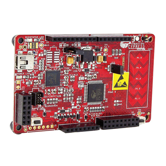
CapSense VIN (J11) Slider PSoC 4 Additional Program Header (J6) PSoC 5LP I/O Header (J8) PSoC 4 Reset Button Arduino Digilent Pmod PSoC 5LP Arduino PSoC 4 User Compatible Compatible Programmer Compatible 44 TQFP Button I/O Header I/O Header (J5) and I/O Header (J1) (J2) Debugger CY8CKIT-042 PSoC® 4 Pioneer Kit Guide, Doc. # 001-86371 Rev. *I... -
Page 18: Pioneer Kit Usb Connection
Composite device USB Input Device USB-I C bridge, KitProg command interface KitProg Programmer and debugger KitProg USB-UART USB-UART bridge, which appears as the COM# port Figure 3-2. KitProg Driver Installation CY8CKIT-042 PSoC® 4 Pioneer Kit Guide, Doc. # 001-86371 Rev. *I... -
Page 19: Programming And Debugging Psoc 4
Figure 3-4 for this implementation. Figure 3-4. SWD Programming PSoC 4 Using PSoC 5LP SWDCLK P2[1] P3[3] Mini P15[6] SWDIO PSoC 5LP PSoC 4 P2[0] P3[2] P15[7] Reset P2[4] XRES CY8CKIT-042 PSoC® 4 Pioneer Kit Guide, Doc. # 001-86371 Rev. *I... - Page 20 USB (VBUS) or by an external source such as an Arduino shield. If the board is already powered from another source, plugging in the USB programmer does not damage the board. CY8CKIT-042 PSoC® 4 Pioneer Kit Guide, Doc. # 001-86371 Rev. *I...
-
Page 21: Using Cy8Ckit-002 Miniprog3 Programmer And Debugger
Note: The CY8CKIT-002 MiniProg3 is not part of the PSoC 4 Pioneer Kit contents. It can be purchased from the Cypress Online Store. Figure 3-7. PSoC 4 Programming/Debugging Using MiniProg3 CY8CKIT-042 PSoC® 4 Pioneer Kit Guide, Doc. # 001-86371 Rev. *I... -
Page 22: Usb-Uart Bridge
PSoC 5LP and PSoC 4. In this example, the PSoC 4 UART has been routed to the J4 header; the user must connect the wires between the PSoC 5LP RX and TX lines available on header J8. CY8CKIT-042 PSoC® 4 Pioneer Kit Guide, Doc. # 001-86371 Rev. *I... - Page 23 1200, 2400, 4800, 9600, 19200, 38400, 57600, and 115200 Data Bits Parity None Stop Bits Flow Control None File transfer protocols Xmodem, 1K Xmodem, Ymodem, Kermit, and Zmodem (only speeds greater supported than 2400 baud). CY8CKIT-042 PSoC® 4 Pioneer Kit Guide, Doc. # 001-86371 Rev. *I...
-
Page 24: Usb-I2C Bridge
SPI/RX8 Ports in the BCP. Figure 3-10. Bridge Control Panel To use the USB_I2C functionality, select the KitProg/<serial_number> in the BCP. On successful connection, the Connected and Powered tabs turn green. CY8CKIT-042 PSoC® 4 Pioneer Kit Guide, Doc. # 001-86371 Rev. *I... -
Page 25: Updating The Onboard Programmer Firmware
Open PSoC Programmer from Start > All Programs > Cypress > PSoC Programmer<version>. When PSoC Programmer opens, a WARNING! window pops up saying that the programmer is currently out of date. Figure 3-12. Firmware Update Warning CY8CKIT-042 PSoC® 4 Pioneer Kit Guide, Doc. # 001-86371 Rev. *I... - Page 26 Click the Utilities tab and click the Upgrade Firmware button. On successful upgrade, the Action and Results window displays the firmware update message with the KitProg version. Figure 3-14. Firmware Updated in PSoC Programmer CY8CKIT-042 PSoC® 4 Pioneer Kit Guide, Doc. # 001-86371 Rev. *I...
-
Page 27: Hardware
CapSense VIN (J11) Slider PSoC 4 Additional Program Header (J6) PSoC 5LP I/O Header (J8) PSoC 4 Reset Button Arduino Digilent Pmod PSoC 5LP Arduino PSoC 4 User Compatible Compatible Programmer Compatible 44 TQFP Button I/O Header I/O Header (J5) and I/O Header (J1) Debugger (J2) CY8CKIT-042 PSoC® 4 Pioneer Kit Guide, Doc. # 001-86371 Rev. *I... - Page 28 I/O Header (J4) A3/P2_3 P1_5 Compatible P0_7/D2 I/O Header (J2) A4/P2_4 P1_4 P0_5/D1 A5/P2_5 P1_3 P0_4/D0 P0_0 P0_1 P1_2 P1_0 P1_1 PSoC 4 Pioneer Kit Digilent Pmod Arduino UNO CY8CKIT-042 PSoC® 4 Pioneer Kit Guide, Doc. # 001-86371 Rev. *I...
-
Page 29: Theory Of Operation
The input voltage is regulated by a low drop-out (LDO) regulator to 3.3 V. You can select between VBUS (5 V) and 3.3 V by suitably plugging the jumper onto the voltage selection header VDD. CY8CKIT-042 PSoC® 4 Pioneer Kit Guide, Doc. # 001-86371 Rev. *I... -
Page 30: Functional Description
Drive modes, strengths, and slew rates are programmable ❐ PSoC Creator design environment ■ Integrated development environment (IDE) provides schematic design entry and build (with ❐ analog and digital automatic routing) CY8CKIT-042 PSoC® 4 Pioneer Kit Guide, Doc. # 001-86371 Rev. *I... -
Page 31: Psoc 5Lp
20 to 24 programmable logic device (PLD) based universal digital blocks (UDBs) ❐ Full CAN 2.0b 16 RX, 8 TX buffers ❐ Full-Speed (FS) USB 2.0 12 Mbps using internal oscillator ❐ CY8CKIT-042 PSoC® 4 Pioneer Kit Guide, Doc. # 001-86371 Rev. *I... - Page 32 Internal PLL clock generation up to 67 MHz ❐ 32.768-kHz watch crystal oscillator ❐ Low-power internal oscillator at 1, 33, and 100 kHz ❐ For more, see the CY8C58LPxx family datasheet. CY8CKIT-042 PSoC® 4 Pioneer Kit Guide, Doc. # 001-86371 Rev. *I...
-
Page 33: Power Supply System
Note: The 5-V domain is directly powered by the USB (VBUS). For this reason, this domain is unregulated. Figure 4-4. Power Supply Block Diagram with Protection Circuits I/O Header 3.3V MOSFET based Protection Ckt PSoC 4 PSoC 5LP P4 10pin P5LP 10pin P5LP I/O Protection Debug Debug Header CY8CKIT-042 PSoC® 4 Pioneer Kit Guide, Doc. # 001-86371 Rev. *I... - Page 34 Remove jumper J13. Connect the positive terminal of voltage supply to the positive terminal of ❐ the ammeter and the negative terminal of the ammeter to the lower pin of J13. Figure 4-6 shows the required connections. CY8CKIT-042 PSoC® 4 Pioneer Kit Guide, Doc. # 001-86371 Rev. *I...
-
Page 35: Programming Interface
The kit allows programming and debugging of the PSoC 4 in two modes: Using the Onboard PSoC 5LP Programmer and Debugger ■ Using CY8CKIT-002 MiniProg3 Programmer and Debugger ■ CY8CKIT-042 PSoC® 4 Pioneer Kit Guide, Doc. # 001-86371 Rev. *I... -
Page 36: Arduino Compatible Headers (J1, J2, J3, J4, And J12 - Unpopulated)
Similarly, the PSoC 4 pin P1[0] is connected to both pin 17 of the J2 header and pin 7 of the J4 header. Therefore, when using P0[0] or P1[0] from either the J2 or J4 header, there should not be any external signal connected to the other header. CY8CKIT-042 PSoC® 4 Pioneer Kit Guide, Doc. # 001-86371 Rev. *I... - Page 37 PSoC 4 are brought to this header. The port 1 pins additionally connect to the onboard CapSense slider through 560- resistors. When the CapSense feature is not used, remove these resistors to ensure a better performance with these pins. CY8CKIT-042 PSoC® 4 Pioneer Kit Guide, Doc. # 001-86371 Rev. *I...
-
Page 38: Digilent Pmod Compatible Header (J5 - Unpopulated)
Pmod daughter cards. Refer to the “No Load Components” section of A.6 Bill of Materials (BOM) on page 125 for the header part number. Figure 4-10. Pmod Connection CY8CKIT-042 PSoC® 4 Pioneer Kit Guide, Doc. # 001-86371 Rev. *I... -
Page 39: Psoc 5Lp Gpio Header (J8)
Table on page 120 for pin details. Figure 4-12. PSoC 5LP GPIO Header (J8) P5LP_VDD P5LP1_2 P5LP0_0 P5LP0_1 P5LP3_4 P5LP3_5 P5LP3_6 P5LP3_7 P5LP12_6 P5LP12_7 P5LP3_0 6x2 RECPT PSoC 5LP GPIO Extension Header CY8CKIT-042 PSoC® 4 Pioneer Kit Guide, Doc. # 001-86371 Rev. *I... -
Page 40: Capsense Slider
NO LOAD Resistor P4_2 R44 ZERO R20 R21 P0_1 Shield 2200 pF NO LOAD R45 ZERO CSS1 CAPSENSE TUNING CIRCUITRY Shield Setting Default Loaded For CSD CapSense Slider 5 Seg CY8CKIT-042 PSoC® 4 Pioneer Kit Guide, Doc. # 001-86371 Rev. *I... -
Page 41: Pioneer Board Leds
Figure 4-16. Status LED and Power LED P5LP_VDD R3 560 ohm P5LP3_1 0805 0805 330 ohm Status LED Green Power LED Figure 4-17. RGB LED 2.2K 1.5K P1_6 P0_2 P4_VDD 1.5K P0_3 RGB LED CY8CKIT-042 PSoC® 4 Pioneer Kit Guide, Doc. # 001-86371 Rev. *I... -
Page 42: Push Buttons
Note: The PSoC 4 Reset pin (XRES) has an internal pull-up resistor. However, an external pull-up resistor R10 is connected to the PSoC 4 Reset pin on the kit, which is optional and required only in a noisy system. CY8CKIT-042 PSoC® 4 Pioneer Kit Guide, Doc. # 001-86371 Rev. *I... -
Page 43: Code Examples
Follow these steps to open and program code examples: 1. Launch PSoC Creator from Start > All Programs > Cypress > PSoC Creator<version> > PSoC Creator <version>. 2. On the Start page, click CY8CKIT-042 under Start > Kits. A list of code examples appears, as shown in Figure 5-1. - Page 44 6. If the device is yet to be acquired, the Select Debug Target window will appear. Select KitProg/ <serial_number> and click Port Acquire, as shown in Figure 5-4. Figure 5-4. Acquire Device from PSoC Creator CY8CKIT-042 PSoC® 4 Pioneer Kit Guide, Doc. # 001-86371 Rev. *I...
- Page 45 Now, click the Connect button. Figure 5-5. Connect Device from PSoC Creator 8. Click OK to exit the window and start programming. Figure 5-6. Program Device from PSoC Creator CY8CKIT-042 PSoC® 4 Pioneer Kit Guide, Doc. # 001-86371 Rev. *I...
-
Page 46: Using The Micrium® Μc/Probe® Projects
µC/Probe, you can test your embedded design effortlessly, with a few mouse clicks. Cypress provides pre-designed µC/Probe project (workspace) files for CapSense and PWM code examples associated with the CY8CKIT-042 kit. These projects can be found in the kit installation directory in the following folder: <Install_Directory>\Cypress\CY8CKIT-042 PSoC 4 Pioneer Kit\1.0\uCProbe... -
Page 47: Blinking Led
Open Blinking LED.cydwr in the Workspace Explorer and select the suitable pin. Table 5-1. Pin Connection Pin Name Port Name Pin_BlueLED P0_3 (Blue) Figure 5-9. Pin Selection for Blinking LED Project CY8CKIT-042 PSoC® 4 Pioneer Kit Guide, Doc. # 001-86371 Rev. *I... -
Page 48: Flow Chart
LED. Change the period and compare value in the PWM component, as shown in Figure 5-11. Rebuild and reprogram the device to vary the frequency and duty cycle. Figure 5-11. PWM Component Configuration Window CY8CKIT-042 PSoC® 4 Pioneer Kit Guide, Doc. # 001-86371 Rev. *I... -
Page 49: Pwm
Open PWM.cydwr in the Workspace Explorer and select the suitable pins. Table 5-2. Pin Connections Pin Name Port Name Pin_RedLED P1_6 (Red) Pin_GreenLED P0_2 (Green) Pin_BlueLED P0_3 (Blue) Figure 5-13. Pin Selection for PWM Project CY8CKIT-042 PSoC® 4 Pioneer Kit Guide, Doc. # 001-86371 Rev. *I... -
Page 50: Flow Chart
Build and program the code example, and reset the device. Observe the RGB LED cycles through the following color pattern: violet > indigo > blue > green > yellow > orange > red (VIBGYOR) CY8CKIT-042 PSoC® 4 Pioneer Kit Guide, Doc. # 001-86371 Rev. *I... -
Page 51: Deep Sleep
SWD in the System tab of the .cydwr file, as shown in Figure 5-17. Disabling the debug port dis- ables the ability to debug the code example through SWD. CY8CKIT-042 PSoC® 4 Pioneer Kit Guide, Doc. # 001-86371 Rev. *I... - Page 52 Code Examples Figure 5-17. Enable Debug Select CY8CKIT-042 PSoC® 4 Pioneer Kit Guide, Doc. # 001-86371 Rev. *I...
-
Page 53: Flow Chart
Deep-Sleep mode and enter Active mode. The device goes back to Deep-Sleep mode after one second. Note: When the device is in Deep-Sleep mode, the programmer must reacquire the device before programming can start. CY8CKIT-042 PSoC® 4 Pioneer Kit Guide, Doc. # 001-86371 Rev. *I... -
Page 54: Capsense
In this code example, the brightness of the green and red LEDs are varied, based on the position of the user’s finger on the CapSense slider. Figure 5-19. PSoC Creator Schematic Design of CapSense Code Example Note: The EzI2C component is not used when tuning is disabled. CY8CKIT-042 PSoC® 4 Pioneer Kit Guide, Doc. # 001-86371 Rev. *I... - Page 55 Pin_RedLED P1_6 (Red) EZI2C_1:scl P3_0 (SCL) EZI2C_1:sda P3_1 (SDA) Note: The I2C communication lines are not used when tuning is disabled. Figure 5-20. Pin Selection for CapSense Code Example CY8CKIT-042 PSoC® 4 Pioneer Kit Guide, Doc. # 001-86371 Rev. *I...
- Page 56 CapSense slider. When the finger is on segment 5 (P1[5]) of the slider, the green LED is brighter than the red LED; when the finger is on segment 1 (P1[1]) of the slider, the red LED is brighter than the green LED. CY8CKIT-042 PSoC® 4 Pioneer Kit Guide, Doc. # 001-86371 Rev. *I...
-
Page 57: Capsense (With Tuning)
No specific hardware connections are required for this code example because all connections are hard-wired on the board. Open CapSense.cydwr in the Workspace Explorer and select the suitable pins. Table 5-4 Figure 5-20 for the CapSense project pin connections. CY8CKIT-042 PSoC® 4 Pioneer Kit Guide, Doc. # 001-86371 Rev. *I... - Page 58 1. Go to the project's TopDesign.cysch file. Figure 5-23. Top Design File 2. To open the tuner, right-click on the CapSense_CSD component in PSoC Creator and click Launch Tuner. CY8CKIT-042 PSoC® 4 Pioneer Kit Guide, Doc. # 001-86371 Rev. *I...
- Page 59 Code Examples Figure 5-24. Launch Tuner CY8CKIT-042 PSoC® 4 Pioneer Kit Guide, Doc. # 001-86371 Rev. *I...
- Page 60 3. The Tuner GUI opens. Click Configuration to open the configuration window. Figure 5-25. Tuner GUI 4. Set the I2C communication parameters, as shown in the following figure. Figure 5-26. I2C Communication 5. Click OK to apply the settings. CY8CKIT-042 PSoC® 4 Pioneer Kit Guide, Doc. # 001-86371 Rev. *I...
- Page 61 Code Examples 5.6.2.5 Verify Output 1. To start the scanning and communication process, click Start. Figure 5-27. Start Communication CY8CKIT-042 PSoC® 4 Pioneer Kit Guide, Doc. # 001-86371 Rev. *I...
- Page 62 On/Off status for each sensor are represented as a graph. Click the Graphing Properties tab on the bottom-right to select the slider element for which the CapSense results are to be shown in the Graphing tab. CY8CKIT-042 PSoC® 4 Pioneer Kit Guide, Doc. # 001-86371 Rev. *I...
- Page 63 Code Examples 4. Select the sensor parameters to observe, as shown in the following figure. The graph of the selected parameters is shown. Figure 5-29. Sensor Parameter Graph CY8CKIT-042 PSoC® 4 Pioneer Kit Guide, Doc. # 001-86371 Rev. *I...
- Page 64 Code Examples 5. Touch a sensor or slider element and see the increase in raw counts. Figure 5-30. Raw Count Increase CY8CKIT-042 PSoC® 4 Pioneer Kit Guide, Doc. # 001-86371 Rev. *I...
-
Page 65: Advanced Topics
Users who have a Windows operating system that does not have HyperTerminal can use an alternate terminal software such as PuTTY. 1. Create a new CY8CKIT-042 (PSoC 4200) Kit project in PSoC Creator, as shown in the following figures. Select a specific location for your project and name the project as desired. You must select the appropriate target hardware (kit) for this project. - Page 66 Advanced Topics Figure 6-2. Select Empty Schematic Option Figure 6-3. Create Project CY8CKIT-042 PSoC® 4 Pioneer Kit Guide, Doc. # 001-86371 Rev. *I...
- Page 67 3. To configure the UART, double-click or right-click on the UART component and select Configure. Figure 6-5. Open UART Configuration Window 4. Change the component name from UART_1 to UART. CY8CKIT-042 PSoC® 4 Pioneer Kit Guide, Doc. # 001-86371 Rev. *I...
- Page 68 Advanced Topics 5. Configure the UART as shown in the following figures. Figure 6-6. UART Configuration Window Figure 6-7. UART Basic Configuration Window CY8CKIT-042 PSoC® 4 Pioneer Kit Guide, Doc. # 001-86371 Rev. *I...
- Page 69 6. Click Apply and then OK to save the changes made to UART configuration. 7. Select P0[4] for UART RX and P0[5] for UART TX in the Pins tab of <Project.cydwr>. Figure 6-9. Pin Selection CY8CKIT-042 PSoC® 4 Pioneer Kit Guide, Doc. # 001-86371 Rev. *I...
- Page 70 = UART_UartGetChar(); if(0u != ch) /* Send the data through UART. This functions is blocking and waits until there is an entry into the TX FIFO. */ UART_UartPutChar(ch); CY8CKIT-042 PSoC® 4 Pioneer Kit Guide, Doc. # 001-86371 Rev. *I...
- Page 71 UART component. An SCB implementation of UART will route the RX and TX pins to either one of the following subsets: (P0[4], P0[5]) or (P3[0],P3[1]) or (P4[0],P4[1]). CY8CKIT-042 PSoC® 4 Pioneer Kit Guide, Doc. # 001-86371 Rev. *I...
- Page 72 1. Connect USB Mini B to J10. The kit enumerates as a KitProg USB-UART and is available under the Device Manager, Ports (COM & LPT). A communication port is assigned to the KitProg USB-UART. Figure 6-12. KitProg USB-UART in Device Manager CY8CKIT-042 PSoC® 4 Pioneer Kit Guide, Doc. # 001-86371 Rev. *I...
- Page 73 2. Open HyperTerminal and select File > New Connection and enter a name for the new connec- tion and click OK. For PuTTY, double-click the putty icon and select Serial under Connection. Figure 6-13. Open New Connection HyperTerminal PuTTY CY8CKIT-042 PSoC® 4 Pioneer Kit Guide, Doc. # 001-86371 Rev. *I...
- Page 74 USB-UART) in Connect using and click OK. In PuTTY enter the COMX in Serial line to connect to. This code example uses COM12. Figure 6-14. Select Communication Port HyperTerminal PuTTY CY8CKIT-042 PSoC® 4 Pioneer Kit Guide, Doc. # 001-86371 Rev. *I...
- Page 75 Click Session and select Serial under Connection type. Serial line shows the communication port (COM12) and Speed shows the baud rate selected. Click Open to start the communication. Figure 6-15. Configure the Communication Port HyperTerminal PuTTY CY8CKIT-042 PSoC® 4 Pioneer Kit Guide, Doc. # 001-86371 Rev. *I...
- Page 76 HyperTerminal. In PuTTY, enable the Force on under Terminal > Line discipline options to display the typed characters on the PuTTY. Figure 6-17. Enabling Echo of Typed Characters in HyperTerminal CY8CKIT-042 PSoC® 4 Pioneer Kit Guide, Doc. # 001-86371 Rev. *I...
- Page 77 Figure 6-18. Enabling Echo of Typed Characters in PuTTY 6. The COM terminal software displays both the typed data and the looped back data from the PSoC 4 UART. Figure 6-19. Data Displayed on HyperTerminal CY8CKIT-042 PSoC® 4 Pioneer Kit Guide, Doc. # 001-86371 Rev. *I...
- Page 78 Advanced Topics Figure 6-20. Data Displayed on PuTTY CY8CKIT-042 PSoC® 4 Pioneer Kit Guide, Doc. # 001-86371 Rev. *I...
-
Page 79: Using Psoc 5Lp As Usb-I2C Bridge
The following steps describe how to use the USB-I2C bridge, which can communicate between the BCP and the PSoC 4. 1. Create a new CY8CKIT-042 (PSoC 4200) Kit project in PSoC Creator, as shown in the following figures. Select a specific location for your project and name the project as desired. You must select the appropriate target hardware (kit) for this project. - Page 80 Advanced Topics Figure 6-22. Select Empty Schematic Option Figure 6-23. Create Project CY8CKIT-042 PSoC® 4 Pioneer Kit Guide, Doc. # 001-86371 Rev. *I...
- Page 81 Figure 6-24. I2C Component in Component Catalog 3. To configure the I2C component, double-click or right-click on the I2C component and select Configure. Figure 6-25. Open I2C Configuration Window CY8CKIT-042 PSoC® 4 Pioneer Kit Guide, Doc. # 001-86371 Rev. *I...
- Page 82 Advanced Topics 4. Change the component name from I2C_1 to I2C. 5. Configure the I2C with the following settings. Figure 6-26. I2C Configuration Tab Figure 6-27. I2C Basic Tab CY8CKIT-042 PSoC® 4 Pioneer Kit Guide, Doc. # 001-86371 Rev. *I...
- Page 83 /* I2C write buffer */ uint8 rdBuf[10]; /* I2C read buffer */ uint8 indexCntr; uint32 byteCnt; /* Enable the Global Interrupt */ CyGlobalIntEnable; /* Start I2C Slave operation */ I2C_Start(); CY8CKIT-042 PSoC® 4 Pioneer Kit Guide, Doc. # 001-86371 Rev. *I...
- Page 84 != (I2C_I2CSlaveStatus() & I2C_I2C_SSTAT_RD_CMPLT)) /* Clear the read buffer pointer so that the next read operations starts from index 0 */ I2C_I2CSlaveClearReadBuf(); /* Clear the read status bits */ I2C_I2CSlaveClearReadStatus(); CY8CKIT-042 PSoC® 4 Pioneer Kit Guide, Doc. # 001-86371 Rev. *I...
- Page 85 9. Open Protocol Configuration from the Tools menu and select the appropriate I2C Speed. Make sure the I2C speed is the same as the one configured in the I2C component. Click OK to close the window. CY8CKIT-042 PSoC® 4 Pioneer Kit Guide, Doc. # 001-86371 Rev. *I...
- Page 86 A '+' indication after each byte indicates that the transaction was successful and a '–' indicates that the transaction was a failure. Figure 6-32. Entering Commands in BCP CY8CKIT-042 PSoC® 4 Pioneer Kit Guide, Doc. # 001-86371 Rev. *I...
- Page 87 Figure 6-34. Read Data Bytes from the BCP Note: Refer Help Contents under Help in BCP or press [F1] for details of I2C commands. CY8CKIT-042 PSoC® 4 Pioneer Kit Guide, Doc. # 001-86371 Rev. *I...
-
Page 88: Developing Applications For Psoc 5Lp
The bootloader hex file is available in the kit files or can be downloaded from the webpage. The hex files are included in the following kit installer directory: <Install_Directory>\CY8CKIT-042 PSoC 4 Pioneer Kit\ <version>\Firmware\Programmer\KitProg_Bootloader Figure 6-36. KitProg Bootloader Hex File Location CY8CKIT-042 PSoC® 4 Pioneer Kit Guide, Doc. # 001-86371 Rev. *I... - Page 89 Type > Bootloadable. Beginning with PSoC Creator 3.2, the Application Type option is removed from the New Project window and the Build Settings menu. PSoC Creator 3.2 and later versions automatically recognize the application type from the TopDesign schematic. CY8CKIT-042 PSoC® 4 Pioneer Kit Guide, Doc. # 001-86371 Rev. *I...
- Page 90 3. Choose Empty schematic in the Select project template dialog, as shown in Figure 6-39. Click Next. Figure 6-39. Choose Empty Schematic 4. In the Create Project dialog, choose the workspace name, location, and project name (Figure 6-40). Click Finish. CY8CKIT-042 PSoC® 4 Pioneer Kit Guide, Doc. # 001-86371 Rev. *I...
- Page 91 Figure 6-40. Create Project Dialog 5. Navigate to the Schematic view and drag and drop a bootloadable component on the top design. Figure 6-41. Bootloadable Component in Component Catalog CY8CKIT-042 PSoC® 4 Pioneer Kit Guide, Doc. # 001-86371 Rev. *I...
- Page 92 Browse button. Select the KitProg_Bootloader.hex and KitProg_Bootloader.elf files; click Open. Figure 6-42. Configuration Window of Bootloadable Component Figure 6-43. Selecting KitProg Bootloader Hex File CY8CKIT-042 PSoC® 4 Pioneer Kit Guide, Doc. # 001-86371 Rev. *I...
- Page 93 4. Develop your custom project. 5. The NVL setting of the Bootloadable project and the KitProg_Bootloader project must be the same. The KitProg_Bootloader.cydwr system settings is shown in the following figure. CY8CKIT-042 PSoC® 4 Pioneer Kit Guide, Doc. # 001-86371 Rev. *I...
- Page 94 100 ms, the PSoC 5LP enters into bootloader. The PSoC 5LP also enters into bootloader when the power supply jumper for the PSoC 4 (J13) is removed and subsequently the USB Mini-B connector is plugged into header J10. CY8CKIT-042 PSoC® 4 Pioneer Kit Guide, Doc. # 001-86371 Rev. *I...
- Page 95 10.In the Bootloader Host tool, click the Open File button to browse to the location of the bootload- able file (*.cyacd). Figure 6-49. Opening Bootloadable File from Bootloader Host Tool CY8CKIT-042 PSoC® 4 Pioneer Kit Guide, Doc. # 001-86371 Rev. *I...
- Page 96 4. The status LED does not function unless used by the custom project. ® For additional information on bootloaders, refer to Cypress application note, AN73503 - PSoC HID Bootloader. CY8CKIT-042 PSoC® 4 Pioneer Kit Guide, Doc. # 001-86371 Rev. *I...
-
Page 97: Building A Normal Project For Psoc 5Lp
6.3.2 Building a Normal Project for PSoC 5LP A normal project is a completely new project created for the PSoC 5LP device on the CY8CKIT-042. Here the entire flash of the PSoC 5LP is programmed, overwriting all bootloader and programming code. - Page 98 Advanced Topics Figure 6-52. Select Device 3. Choose Empty schematic in the Select project template dialog, as shown in Figure 6-53. Click Next. Figure 6-53. Choose Empty Schematic CY8CKIT-042 PSoC® 4 Pioneer Kit Guide, Doc. # 001-86371 Rev. *I...
- Page 99 4. When a normal project is programmed onto the PSoC 5LP, the initial capability of the PSoC 5LP to act as a programmer, USB-UART bridge, or USB-I2C bridge in not available. 5. The status LED does not function unless used by the custom project. CY8CKIT-042 PSoC® 4 Pioneer Kit Guide, Doc. # 001-86371 Rev. *I...
-
Page 100: Psoc 5Lp Factory Program Restore Instructions
Advanced Topics PSoC 5LP Factory Program Restore Instructions The CY8CKIT-042 PSoC 4 Pioneer Kit features a PSoC 5LP device that comes factory-programmed as the onboard programmer and debugger for the PSoC 4 device. In addition to creating applications for the PSoC 4 device, you can also create custom applications for the PSoC 5LP device on this kit. - Page 101 4. Switch to the Utilities tab in PSoC Programmer and press the Upgrade Firmware button. Unplug all other PSoC programmers (such as MiniProg3 and DVKProg) from the PC before pressing the Upgrade Firmware button. Figure 6-56. Upgrade Firmware CY8CKIT-042 PSoC® 4 Pioneer Kit Guide, Doc. # 001-86371 Rev. *I...
- Page 102 Figure 6-57. Firmware Update Complete 6. The factory program is now successfully restored on the PSoC 5LP. It can be used as the pro- grammer/debugger for the PSoC 4 device. CY8CKIT-042 PSoC® 4 Pioneer Kit Guide, Doc. # 001-86371 Rev. *I...
- Page 103 1. Launch the Bootloader Host tool from Start > Cypress > PSoC Creator. 2. Using the File > Open menu, load the Kit Prog.cyacd file, which is installed with the kit software. The default location for this file is: <Install_Directory>\CY8CKIT-042 PSoC 4 Pioneer Kit\<version>\Firmware\Programmer\KitProg\KitProg.cyacd Figure 6-58.
- Page 104 5. Click the Program button (or menu item Actions > Program) to restore the factory-program by bootloading it onto the PSoC 5LP. 6. After programming has completed, the following message appears: “Programming Finished Suc- cessfully”. CY8CKIT-042 PSoC® 4 Pioneer Kit Guide, Doc. # 001-86371 Rev. *I...
-
Page 105: Psoc 5Lp Is Programmed With A Standard Application
1. Launch PSoC Programmer 3.27.1 or later from Start > Cypress > PSoC Programmer. 2. Use the File > Open menu to load the KitProg.hex factory program hex file, which is shipped with the kit. The default location for this file is: <Install_Directory>\CY8CKIT-042 PSoC 4 Pioneer Kit\<version>\Firmware\Programmer\KitProg 3. - Page 106 If the board is not powered over USB, select the Power Cycle programming mode. Figure 6-61. Select MiniProg3 5. When ready, press the Program button (or File > Program) to program the PSoC 5LP device. CY8CKIT-042 PSoC® 4 Pioneer Kit Guide, Doc. # 001-86371 Rev. *I...
-
Page 107: Using Μc/Probe Tool
Manual. To learn more about the µC/Probe, visit: micrium.com/tools/ucprobe/overview/. In Micrium µC/Probe, the Cypress KitProg is being supported as a means of communication to the target device connected to PC. CY8CKIT-042 PSoC® 4 Pioneer Kit Guide, Doc. # 001-86371 Rev. *I... -
Page 108: Capsense Code Example
CapSense Code Example To visualize the output of CapSense project using µC/Probe tool, follow the steps given below: 1. Program the CapSense code example on CY8CKIT-042 by following steps 1–8 in chapter 5. 2. Download and install µC/Probe tool from https://www.micrium.com/download/ucprobe-win-... - Page 109 5. Next, add a RGB Palette from Writable Controls in Toolbox on to the Datascreen1. Figure 6-65. Adding RGB Palette Control 6. The DataScreen1 looks as below after adding both the controls. Figure 6-66. DataScreen with Slider and RGB controls CY8CKIT-042 PSoC® 4 Pioneer Kit Guide, Doc. # 001-86371 Rev. *I...
- Page 110 10.Now, expand the main.c file to view the global variables defined in main.c file. Figure 6-68. Global variables in Symbol Browser CY8CKIT-042 PSoC® 4 Pioneer Kit Guide, Doc. # 001-86371 Rev. *I...
- Page 111 11. Drag and drop the global variable µcSlider on to the custom slider control to see the slider output. Similarly, drag and drop the global variable µcARGB on to the RGB Palette to see the RGB output. Figure 6-69. Assigning slider output to Custom Slider control CY8CKIT-042 PSoC® 4 Pioneer Kit Guide, Doc. # 001-86371 Rev. *I...
- Page 112 Advanced Topics Figure 6-70. Assigning RGB output to RGB Palette control 12.Connect the CY8CKIT-042 to the computer. Click the Settings button in the µC/Probe tool. Figure 6-71. Settings Button in µC/Probe CY8CKIT-042 PSoC® 4 Pioneer Kit Guide, Doc. # 001-86371 Rev. *I...
- Page 113 13.In the µC/Probe setting window, select the Cypress PSoC Prog and select ‘KitProg/<Kit Prog number>’ from the drop down box for Port and click OK to start communication between the CY8CKIT-042 and the µC/Probe tool. Figure 6-72. µC/Probe Settings CY8CKIT-042 PSoC® 4 Pioneer Kit Guide, Doc. # 001-86371 Rev. *I...
-
Page 114: Pwm Code Example
The µC/Probe project for PWM project is already created and packaged along with kit content. The µC/Probe projects can be found in the installation folder at <Install_Directory>\CY8CKIT- 042 PSoC 4 Pioneer Kit\<version>\µCProbe. 1. Program the PWM code example on CY8CKIT-042 by following steps 1–8 in 5.4 PWM on page 2. - Page 115 3. Browse and point to the PWM.elf file to load the symbols (global variables) from the PWM code example. 4. Connect the CY8CKIT-042 to PC and follow steps 12 to 14 described above to start running the datascreen. 5. The PWM compare values are displayed graphically and the RGB palette displays the RGB LED output on the datascreen.
-
Page 116: Appendix
P2_7 P0_1 P0_0 P0_0 P3_0 P4_3 P3_0 P4_3 10000 pF 2 PIN HDR Sh_tank NO LOAD R6 ZERO P4_VDD VTARG R4 ZERO 0603 P4_VDD 4.7K P4_VDD /XRES PSoC 4 CY8CKIT-042 PSoC® 4 Pioneer Kit Guide, Doc. # 001-86371 Rev. *I... - Page 117 Default Loaded For CSD P0_7 EVQ-PE105K CapSense Slider 5 Seg USER BUTTON 2.2K 1.5K P1_6 P0_2 P4_VDD 1.5K P0_3 RGB LED P5LP_VDD P5LP3_1 0805 330 ohm Status LED Green User Interface CY8CKIT-042 PSoC® 4 Pioneer Kit Guide, Doc. # 001-86371 Rev. *I...
- Page 118 1.5K 1.0 uF 0.1 uF 0603 0402 P5LP_XRES PSoC 5LP Programmer / Debugger NO LOAD R46 ZERO PMOS( DMP3098L-7) V3.3_EXT V3.3 442 ohm PMOS( DMP3098L-7) 1K ohm Protection Circuit CY8CKIT-042 PSoC® 4 Pioneer Kit Guide, Doc. # 001-86371 Rev. *I...
- Page 119 P0_3 P0_4 P2_2 P0_5 P2_3 P1_5 P0_7 P2_4 P1_4 P3_7 P2_5 P1_3 P0_0 P0_0 P3_5 P0_1 P1_2 P1_0 P1_0 P1_1 P2_7 9x2 RECP 8x1 RECP (J1-J4) Arduino Compatible Headers CY8CKIT-042 PSoC® 4 Pioneer Kit Guide, Doc. # 001-86371 Rev. *I...
-
Page 120: Pin Assignment Table
P2[5] A5 (SARADC input) J2_12 P1[3] Opamp 2out J2_13 P0[0] Comparator 1+ J2_14 J2_15 P0[1] Comparator 1– J2_16 P1[2] Opamp 1out J2_17 P1[0] Opamp 1+ J2_18 P1[1] Opamp 1– CY8CKIT-042 PSoC® 4 Pioneer Kit Guide, Doc. # 001-86371 Rev. *I... - Page 121 P3[5] D5(PWM) J4_07 P1[0] D6(PWM) J4_08 P2[7] Kit Signal PSoC 4 Description J12_01 P3[1] MISO J12_02 PSoC 4_VDD J12_03 P0[6] J12_04 P3[0] MOSI J12_05 /XRES PSoC 4 RESET J12_06 CY8CKIT-042 PSoC® 4 Pioneer Kit Guide, Doc. # 001-86371 Rev. *I...
- Page 122 Digilent Pmod Cards Support Header (J5) PSoC 4 Description Kit Signal (Default Pmod Signals) J5_01 P3[5] SPI_SS (multiplex with J4_06) J5_02 P3[0] SPI_MOSI J5_03 P3[1] SPI_MISO J5_04 P0[6] SPI_SCK J5_05 J5_06 CY8CKIT-042 PSoC® 4 Pioneer Kit Guide, Doc. # 001-86371 Rev. *I...
-
Page 123: Program And Debug Headers
PSoC 5LP Direct Program/Debug Header (J7) PSoC 5LP PSoC 5LP Description Description Signal Signal J7_01 J7_02 P1[0] TMS/SWDIO J7_03 J7_04 P1[1] TCLK/SWCLK J7_05 J7_06 P1[3] TDO/SWO J7_07 J7_08 P1[4] J7_09 J7_10 XRES RESET CY8CKIT-042 PSoC® 4 Pioneer Kit Guide, Doc. # 001-86371 Rev. *I... -
Page 124: Use Of Zero-Ohm Resistors And No Load
PSoC 5LP pro- successfully grammer. Note: LED status is not applicable when a custom project is running in PSoC 5LP. CY8CKIT-042 PSoC® 4 Pioneer Kit Guide, Doc. # 001-86371 Rev. *I... -
Page 125: Bill Of Materials (Bom)
CONN HEADER FMAL 12PS.1" DL Sullins Connector 6x2 RECP PPPC062LFBN-RC GOLD Solutions CONN HEADER VERT SGL 3POS 3p_jumper 961103-6404-AR GOLD CONN USB MINI AB SMT RIGHT USB Mini B TE Connectivity 1734035-2 ANGLE CY8CKIT-042 PSoC® 4 Pioneer Kit Guide, Doc. # 001-86371 Rev. *I... - Page 126 68QFN PSoC 5LP chip for USB debug Cypress Semicon- (CY8C5868L CY8C5868LTI-LP039 channel and USB-Serial interface ductor TI-LP039 ) No Load Components CAP CERAMIC 1.0UF 25V X5R 0603 1.0 uFd Taiyo Yuden TMK107BJ105KA-T CY8CKIT-042 PSoC® 4 Pioneer Kit Guide, Doc. # 001-86371 Rev. *I...
-
Page 127: Regulatory Compliance Information
Cypress Semicon- Kit QR code ductor Regulatory Compliance Information The CY8CKIT-042 PSoC 4 Pioneer Kit has been tested and verified to comply with the following electromagnetic compatibility (EMC) regulations: EN 55022:2010 Class A - Emissions ■ EN 55024:2010 Class A - Immunity ■... -
Page 128: Migrating Projects Across Different Pioneer Series Kits
Figure A-1. Pioneer series kits pin map Arduino compatible Pioneer series kits I/O headers CY8CKIT-040 Arduino compatible 6x1 header power header CY8CKIT-042-BLE 6x2 header CY8CKIT-042 & CY8CKIT-044 9x2 header CY8CKIT-042 PSoC® 4 Pioneer Kit Guide, Doc. # 001-86371 Rev. *I... - Page 129 P1[0] – – P0[7] – – – P1[1] P3[5] * These pins are also used for on-board peripherals. See the tables in the On-Board Peripherals section below for details. CY8CKIT-042 PSoC® 4 Pioneer Kit Guide, Doc. # 001-86371 Rev. *I...
- Page 130 P1[0] P1[0] P1[1] P5[3] P2[7] P1[0] P5[5] P2[0] * These pins are also used for on-board peripherals. See the tables in the On-Board Peripherals section below for connection details. CY8CKIT-042 PSoC® 4 Pioneer Kit Guide, Doc. # 001-86371 Rev. *I...
- Page 131 P0[6] Green P0[2] P1[1] P3[6] P2[6] Blue P0[3] P0[2] P3[7] P6[5] User Switch Pin Map Pioneer series kits Pin # Description CY8CKIT-042 CY8CKIT-040 CY8CKIT-042-BLE CY8CKIT-044 P0[7] – P2[7] P0[7] CY8CKIT-042 PSoC® 4 Pioneer Kit Guide, Doc. # 001-86371 Rev. *I...
-
Page 132: Revision History
Modified the CapSense code example. Updated Introduction chapter on page Updated “Additional Learning Resources” on page SASH / 4757883 05/07/2015 Updated description. MSUR Updated “PSoC Creator Code Examples” on page Updated Figure 1-4. CY8CKIT-042 PSoC® 4 Pioneer Kit Guide, Doc. # 001-86371 Rev. *I... - Page 133 Updated description. Updated Hardware chapter on page Updated “Functional Description” on page Updated “Arduino Compatible Headers (J1, J2, J3, J4, and J12 - unpopu- lated)” on page Updated description. CY8CKIT-042 PSoC® 4 Pioneer Kit Guide, Doc. # 001-86371 Rev. *I...
- Page 134 “Launching Tuner GUI” on page Updated Figure 5-24. Updated Figure 5-25. Updated “Verify Output” on page Updated description. Updated Figure 5-27. Updated Figure 5-28. Updated Figure 5-29. Updated Figure 5-30. CY8CKIT-042 PSoC® 4 Pioneer Kit Guide, Doc. # 001-86371 Rev. *I...
- Page 135 “Restore PSoC 5LP Factory Program Using PSoC Program- mer” on page 100: Updated description. Updated “PSoC 5LP is Programmed with a Standard Application” on page 105: Updated description. Added “Using µC/Probe Tool” on page 107. CY8CKIT-042 PSoC® 4 Pioneer Kit Guide, Doc. # 001-86371 Rev. *I...
- Page 136 5740267 05/17/2017 AESATMP8 Updated logo and Copyright. Update images. Minor content updates throughout the document 6111693 03/27/2018 SAGA Updated schematics Added “Using the Micrium® µC/Probe® Projects” on page 46 CY8CKIT-042 PSoC® 4 Pioneer Kit Guide, Doc. # 001-86371 Rev. *I...
Need help?
Do you have a question about the CY8CKIT-042 and is the answer not in the manual?
Questions and answers