
Related Manuals for AccuTemp ACCU-STEAM G2 Series


Summary of Contents for AccuTemp ACCU-STEAM G2 Series
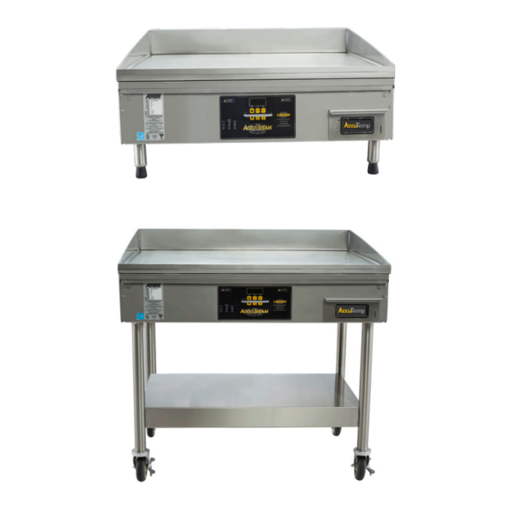
- Page 1 ACCU-STEAM GAS G2 GRIDDLE SERVICE MANUAL AccuTemp Products, Inc. · 8415 North Clinton Park · Fort Wayne, IN 46825 ·800 210-5907 · accutemp.net SP8042-1911...
- Page 2 In order to establish full compliance with Proposition 65, a yellow warning label has been attached to each gas fired unit manufactured by AccuTemp Products,Inc. Carbon monoxide would not be present in concentrations that would pose a “significant risk”...
-
Page 3: Table Of Contents
Table of Contents 1.0 Warnings and Cautions 1.1 Warning Symbol Definitions 1.2 Safety Precautions 2.0 Griddle Specification 2.1 Equipment Data Plate 3.0 Sequence of Operation 4.0 Troubleshooting Guide 4.1 Troubleshooting Flowchart 4.2 Diagnosis Table 5.0 Digital Controller 5.1 Operation 5.2 Managers Mode 5.3 Set RTD Probe Offset 6.0 Main Component Identification 7.0 Removal and Replacement of Components... -
Page 4: Warnings And Cautions
1. WARNINGS AND CAUTIONS 1.1 Warning Symbol Definitions Symbols are used to attract your attention to possible dangers. They are only effective if the operator uses proper accident prevention measures. Some of the symbols are boxed text; while others maybe just picture icons. Please give this information the respect they deserve for safe operation. -
Page 5: Safety Precautions
1.2 Safety Precautions The Safety Instructions listed on this page below, should be posted in a prominent location as a reminder of safe practices; as well as, recommended actions to follow in the event of an equipment or facility’s utility issue. Electrical shock hazard while working on energized equipment Unplug equipment prior to removing any components effected by electricity. -
Page 6: Griddle Specification
(COOKING WIDTH) 4.84 3.54 22.75 MM5208-1803 Fig 2.A AccuTemp Products, Inc. (COOKING WIDTH) 8415 North Clinton Park • Fort Wayne, IN 46825 • 800-210-5907 • 260-493-0415 • Fax 260-493-0318 • accutemp.net UNIT DEPTH (COOKING HEIGHT) 42.25 36.05 (COOKING HEIGHT) 27.65 MM5209-1803 (COOKING DEPTH) Fig 2.B... -
Page 7: Equipment Data Plate
2.1 Equipment Data Plate Model: AA B CCC D E FF GG Example: GGF1201A4850 A is the base model N = Natural Gas, P = Propane B is the model configuration CCC is the supply Voltage D is the number of phases: 1 or 3 E is the depth F is the width G is the special configuration... -
Page 8: Sequence Of Operation
3. Sequence of Operation 1. When the G2 griddle is plugged in, AC line voltage is supplied to the primary side of the transformer. 2. The voltage out of the secondary side of the transformer is 24VAC nominal. Yellow and blue wires out of the transformer. 3. - Page 9 through the combination gas valve, through the orifices in each main burner and through the main burner tiles. 12. When the gas/air mixture is ignited, the flame sense probe will detect a DC voltage level through the flame’s ionized gas to ground via the orange flame sense wire harness to the ignition module, pin #6.
-
Page 10: Troubleshooting Guide
4. Troubleshooting Guide 4.1 Flowchart UNIT FAULT LIGHT/ POWER UNIT ON? HEAT ON? ERROR CODE? ERROR CODE UNIT PLUGGED E001? HEAT LIGHT ON? E002? UNIT HEATING OVERTEMP? BREAKER ON? CHECK FAULT LIGHT PROPER INTERNAL FLASHING TEMPERATURE VOLTAGE UNIT CORRECT FAULT LIGHT ON OPERATING VOLTAGE NORMAL... -
Page 11: Diagnosis Table
4.2 Diagnosis Table Power cord Confirm proper voltage at outlet. disconnected Plug in power cord. Breaker is Unplug griddle and check line voltage at outlet. tripped Reset breaker. Temperature • If 24VAC is on secondary side of transformer, check power input Controller terminals of Temp Controller J2-1 &... - Page 12 GAS VALVE Error Code • E001: Open Temp (RTD) sensor J3-1 & J3-2. Check terminals for poor E001 or E002 crimping. on display • E002: Shorted Temp (RTD) sensor J3-1 & J3-2. AT2E-4717-1 • If RTD checks good, reconnect RTD and cycle power. Is error code still FLAME SENSE PROBE HV IGNITOR present - Replace Temperature Controller.
- Page 13 CONTROLLER Relay, DC DIGITAL HEAT OVER CONTROLLER RLY 2 Accu-Steam™ G2 Gas Service Manual N.C. TEMP AT0E-3880-1 DC COIL SP8042-1911 E-1800-2 HI-LIMIT CONTROL T LAMP, RED AT0E-3625-5 Control Board AccuTemp Products, Inc. 8415 N. Clinton Park Fort Wayne, IN 46825...
- Page 14 INPUT INPUT GH LIMIT N.O. AT0E-2825-6 +24V TROLLER Relay, DC DIGITAL CONTROLLER RLY 2 N.C. 80-1 DC COIL NTROL AT0E-3625-5 Control Board AccuTemp Products, Inc. 8415 N. Clinton Park Fort Wayne, IN 46825 Accu-Steam™ G2 Gas Service Manual SP8042-1911 SCHEMATIC,...
-
Page 15: Digital Controller
5. Digital Controller 5.1 Operation Fig 5.A When power is applied to the control, the control will configure itself to operate in accordance with the parameters stored in memory. These parameters may be adjusted using Manager’s Mode. Unplug griddle from wall receptacle before replacing the control board in order to prevent damage to equipment. -
Page 16: Managers Mode
5.2 Managers Mode Managers mode is used to setup initial operational parameters for the appliance prior to the first time of production use. Manager’s mode 1. Entering Managers mode, press and hold the DOWN arrow key and the Asterisk key together for about eight seconds, to initiate the programming mode. -
Page 17: Set Rtd Probe Offset
5.3 Set RTD Probe Offset In certain circumstances, the measurement from the RTD probe can be adjusted at the control board, thereby adjusting when the unit will call for heat. This process should only be performed by a qualified technician with access to a weighted surface probe. -
Page 18: Main Component Identification
6. Main Component Identification Power Cord • Includes plug for connection to 120V AT0A-2911-1 outlet. Transformer • Steps down the line voltage to AT0E-2662-7 approximately 24VAC nominal SN 18282 and above (When replacing under SN 18182 use kit AT0A-5076-1). Timer, Ignition Fault •... - Page 19 Digital Control Board • Receives input signal from RTD AT0E-3625-5-R** (R** refers to software Temperature Sensor. revision of board programming). • Sends DCV output signal to Control Relay coil which controls igntion module. Fuse .75 Amp 250v • The .75A fuse is to provide protection AT0E-2731-4 to the control circuitry in case of a short in the system.
-
Page 20: Removal And Replacement Of Components
7. Removal and Replacement of Components. 7.1 Voltage Supply Components Fuse .75 Amp 250V AT0E-2731-4 1. Unplug from wall receptacle. 2. Lower front access panel by removing the screws in the upper corners of the panel (Fig 7.1A). 3. Replace fuse. Ensure that the fuse block holder is secure and the fuses do not slip once in place as this can cause ignition issues... -
Page 21: R&R Of Control Boards
7.2 Control Boards Digital Control Board AT0E-3625-5 Failure to unplug the unit before pulling wires from the board could result in fatal damage to the controller. 1. Unplug from wall receptacle. 2. Lower front access panel by removing the screws in the upper corners of the panel. 3. -
Page 22: R&R Of Ignition System Components
7.3 Ignition System Components Control Relay AT0E-2825-6 1. Unplug from wall receptacle. 2. Lower front access panel by removing the screws in the upper corners of the panel. 3. Take note of wire location. 4. Remove wires and hardware securing relay (Fig 7.3A). - Page 23 Gas Valve AT2E-1806-2 1. Unplug from wall receptacle. 2. Turn off gas supply and disconnect the unit from supply hose. 3. Lower front access panel by removing the screws in the upper corners of the panel. 4. Take note of or mark wire location and remove wires.
- Page 24 Flame Sensor AT2E-4717-1 1. Unplug from wall receptacle. 2. Lower front access panel by removing the screws in the upper corners of the panel. 3. Remove orange flame sense wire (Fig 7.3G). 4. Remove screws and flame sensor. Fig 7.3G 5.
- Page 25 Infrared Burner AT2B-2099-2 When diagnosing a bad burner, often times the exterior back side of the burner will have black or gray discoloration in a circular or half moon shaped pattern (Fig 7.3J). Fig 7.3J 1. Unplug from wall receptacle. 2.
- Page 26 7. Using a 5/8th inch open wrench, remove gas line from compression elbow (Fig Fig 7.3N). 8. Remove rear 2 fasteners fully and loosen front 2 fasteners securing burner (Fig Fig 7.3O). 9. Allow rear of burner to drop, slide backwards, away from loosened front fasteners. 10.
-
Page 27: R&R Of Temperature Sensors
7.4 Temperature Sensors Temperature Sensor, 1000 Ω RTD Fig 7.4A AT0E-5062-1 1. Unplug from wall receptacle. 2. Lower front access panel by removing the screws in the upper corners of the panel. 3. Locate and remove RTD wires attached to the main control board. -
Page 28: Extended Troubleshooting
mperature Measurement ermal contact, clean flat surfaces should make full contact with one another. Point 8. Extended Troubleshooting not achieve good thermal contact and will not give accurate temperature 8.1 Griddle Surface Temperature Measurement mperature measurements of a griddle surface in the field it is recommended to use To achieve good thermal contact, clean flat surfaces should make full contact with one another. -
Page 29: Ignition System Testing
When trouble shooting ignition problems it is absolutely imperative to start off by taking incoming/outgoing gas pressure and to get a reading from the flame sensor. These three measurement are the most useful readings a technician can take when diagnosing AccuTemp gas equipment and are often the most neglected. - Page 30 When trouble shooting ignition problems it is absolutely imperative to start off by taking incoming/outgoing gas pressure and to get a reading from the flame sensor. These three measurement are the most useful readings a technician can take when diagnosing AccuTemp gas equipment and are often the most neglected.
-
Page 31: Planned Maintenance
9. Planned Maintenance It is recommended that you contact your AccuTemp authorized service provider to setup a planned maintenance program to keep your appliance operating in the most efficient manner. Accutemp recommends a minimum of a yearly schedule. PM DESCRIPTION... -
Page 32: Wiring Schematic
10. Wiring Schematic AT2T-3912-1 120V-240V ACCU-STEAM G2 GAS GRIDDLE Accu-Steam™ G2 Gas Service Manual SP8042-1911... -
Page 33: Limited Warranty
LIMITED WARRANTY One Year Labor and Parts AccuTemp Products, Inc. ( AccuTemp ) warrants that your AccuTemp equipment will be free of defects in material and workmanship under normal use for a period of twelve (12) months from installation or fifteen (15) months from date of shipment from AccuTemp, whichever date first occurs (the Warranty Period ).
Need help?
Do you have a question about the ACCU-STEAM G2 Series and is the answer not in the manual?
Questions and answers