Advertisement
Quick Links
Serial Number:
Model:
INSTALLATION/OPERATORS MANUAL
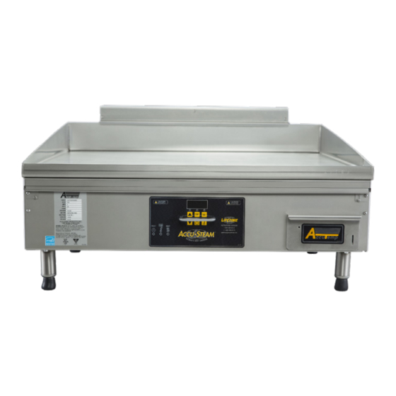
ACCU-STEAM GAS G2 GRIDDLE
MODELS
GG24A/GG36A/GG48A
GG24B/GG36B/GG48B
PG24A/PG36A/PG48A
PG24B/PG36B/PG48B
This manual should be retained for future
reference
AccuTemp Products INC
8415 N. Clinton Park Dr, Fort Wayne IN 46825
www.accutemp.net
MP5017-1907
Advertisement

Related Manuals for AccuTemp Accu-STEAM GG24A


Summary of Contents for AccuTemp Accu-STEAM GG24A
- Page 1 Serial Number: Model: INSTALLATION/OPERATORS MANUAL ACCU-STEAM GAS G2 GRIDDLE MODELS GG24A/GG36A/GG48A GG24B/GG36B/GG48B PG24A/PG36A/PG48A PG24B/PG36B/PG48B This manual should be retained for future reference AccuTemp Products INC 8415 N. Clinton Park Dr, Fort Wayne IN 46825 www.accutemp.net MP5017-1907...
- Page 2 In order to establish full compliance with Proposition 65, a yellow warning label has been attached to each gas fired unit manufactured by AccuTemp Products,Inc. Carbon monoxide would not be present in concentrations that would pose a “significant risk”...
- Page 3 TABLE OF CONTENTS SAFETY WARNINGS INFORMATION PAGE 3 GENERAL INFORMATION PAGE 7 START UP FORM PAGE 10 INSTALLATION PAGE 12 OPERATION - USE PAGE 17 OPERATION - CLEANING PAGE 26 PLANNED MAINTENANCE PAGE 27 SERVICE & TROUBLESHOOTING PAGE 30 WARRANTY PAGE 33 DOCUMENT HISTORY CURRENT...
- Page 4 1. WARNING SYMBOL DEFINITIONS SYMBOL DEFINITIONS Symbols are used to attract your attention to possible dangers. They are only effective if the operator uses proper accident prevention measures. Some of the symbols are boxed text; while others maybe just picture icons. Please give this information the respect they deserve for safe operation.
- Page 5 1.1 IMPORTANT FOR YOUR SAFETY The safety instructions listed below on this page should be posted in a prominent location as a reminder of safe practices as well as recommended actions to follow in the event of an equipment or facility utility issue. WARNING In the event a gas odor is detected, shut down all appliances at the main gas shut-off valve and contact the local gas company or gas supplier service.
- Page 6 Intended for other than household use. AccuTemp equipment. It is imperative that to use Genuine AccuTemp Replacement Parts Plug the appliance into a properly to avoid injury or damage to the commercial grounded electrical outlet of the correct appliance.
- Page 7 Temperatures in and around the appliance are very hot and can cause severe burns. To avoid damage to the cooking surface of this appliance do not use abrasive cleaners such as a griddle stone or brick. To avoid personal injury or damage to the appliance do not use a water jet to clean the unit.
- Page 8 (COOKING HEIGHT) 4.84 3.54 22.75 MM5208-1803 Fig 2.A AccuTemp Products, Inc. 8415 North Clinton Park • Fort Wayne, IN 46825 • 800-210-5907 • 260-493-0415 • Fax 260-493-0318 • accutemp.net (COOKING WIDTH) (COOKING HEIGHT) UNIT DEPTH 42.25 36.05 (COOKING HEIGHT) 27.65 Fig 2.B...
- Page 9 2.2 EQUIPMENT DATA PLATE Model: AA B CCC D E FF GG Example: GGF1201A4850 A is the base model N = Natural Gas, P = Propane B is the model configuration CCC is the supply Voltage D is the number of phases: 1 or 3 E is the depth F is the width G is the special configuration...
- Page 10 1. Complete the Installation/Operational Checklist and Warranty Registration Form enclosed in the document packet that was sent with the appliance. 2. Mail, fax or scan and send via e-mail the form to AccuTemp Products, Inc to the contacts listed for each type on the form.
- Page 11 An external regulator should not be used unless the supply gas pressure is more than 0.5 psig/14”WC • If the altitude is greater than 3,000 feet above sea level, contact the AccuTemp Technical Services Department to verify the correct orifice size for the main burners.
- Page 12 ACCU-STEAM Gas Griddle Start-Up Form (continued) 9. Is an external gas regulator connected to the griddle (Circle Y/N) 10. What is the Length and Width of the Gas Supply Line L 11. Gas Pressure measurements Natural Gas: Static WC Dynamic Dynamic pressure should be 5”WC (Regulator valve pressure tap - 1/8NPT) Propane: Static WC Dynamic...
- Page 13 AccuTemp griddle stand or The installation must conform with local codes, directly onto any flat, non combustible level or in the absence of local codes, with the surface that will support the appliance weight.
- Page 14 AccuTemp STAND If on an AccuTemp griddle stand with casters, ensure that the floor surface is level and place the two locking casters to the “on” position and follow the leveling instructions to verify the appliance is level.
- Page 15 3.8.2 ELECTRICAL REQUIREMENTS Electrical requirements are listed on the data plate located on the front right of the control panel. All standard AccuTemp griddles are supplied with a 6ft (1.83m) cord and the appropriate UL listed plug that must be...
- Page 16 3.9 GAS CONNECTION 4. Use a 1/8” NPT tap to connect a manometer to the control valve. Ensure The griddle has a 90° male 1/2” manometer is set to read inches water connection installed (Fig 3.D). column (Fig 3.B & 3.C). The gas supply pressures for the internal 5.
- Page 17 3.9.2 FLAME SENSE RECTIFICATION 3.9.3 IGNITION TROUBLESHOOTING The Accu-Steam Gas Griddle utilizes a flame Should the unit trigger an ignition lockout sensing circuit to determine if the system has during installation and testing, verify the proper combustion. When the system is turned following on, gas is sent to the burner and an electronic ignition tries to ignite the burner.
- Page 18 4.1 OPERATION INTRODUCTION 4. OPERATION RISKS RESULTING FROM CONTACT WITH The ACCU-STEAM G2™ griddle is constructed VERY HOT OBJECT: and uses technology like no other griddle in the world. The stainless steel cooking surface is heated by steam. The griddle steam chamber requires no additional liquid or maintenance.
- Page 19 4.2 VISUAL IDENTIFICATION Overfill Grease Drawer Indicator Display/Operational Keypad Data Tag Grease Drawer Adjustable Bullet Feet Fig 4.B Data Tag Display/Operational Keypad Tech Support Contact Info Operation/Fault Indicators Fig 4.C MP5017-1907 Accu-Steam Gas Griddle...
- Page 20 4.2 CONTROL OVERVIEW The appliance digital temperature control is easy to operate and requires little customer interface. OPERATOR DISPLAY AND KEYPAD 200F OPERATOR DISPLAY LED 1 LED 3 LED 2 PROGRAM KEY PRESET TEMP 1 KEY PRESET TEMP 2 KEY ASTERISK KEY PROGRAM KEY ON/OFF...
- Page 21 4.2.1 PROGRAM SEQUENCE OF 4.2.2 MANAGER MODE PROGRAMMING OPERATION Prior to using the commercial appliance a few operational items need to be determined. Press the ON/OFF switch and the griddle • Default set temperature will start to pre-heat and LED 1 will blink Any •...
- Page 22 Managers mode is used to setup initial operational parameters for the appliance prior to the first time of production use. Manager’s mode 1. Entering Managers mode, press and hold the DOWN arrow key and the Asterisk key together for about eight seconds, to initiate the programming mode. When the mode is accessed, all three LED lights will blink synchronously.
- Page 23 4.2.3 CONTROL REFERENCE GUIDE MODE LED Indicators DISPLAY NOTES All LED’s are off when Off when powered down. On/Off key. To turn unit on: depress the powered down. When powered On, the To turn off the unit, disable outputs, save the controller would FLASH current set point temperature (see details in at a 1 Hz rate the current...
- Page 24 MODE LED Indicators DISPLAY NOTES Set Preset All indicator LEDs Set Point Value Use the same process to change the Temperature blinking. Then the temperature as detailed in Set Temperature selected preset key (On the fly), to adjust the Set Temperature. will blink for 3 -5 Once the correct temperature is displayed, seconds.
- Page 25 4.3 COOKING 4.3.1 CLEAN AFTER INSTALLATION 400° F (204°C). The appliance will be preheated when the selected set temperature is displayed It is recommended that you clean your and the corresponding LED goes solid. Please ACCU-STEAM™ griddle thoroughly before use caution as temperatures on and around using it for the first time.
- Page 26 4.3.4 CHECKING SURFACE TEMPERATURES The digital temperature control and temperature sensor are more accurate than any other device to measure the cooking surface temperature in this appliance. Any other digital device may show a difference. The important use of the external temperature measuring device is to ascertain that the temperatures are within ±5°F across the entire cooking surface of the...
- Page 27 4.4 CLEANING • After the non-cooking surfaces are cool Always disconnect from power source to the touch. Empty the grease tray and before cleaning or servicing. wash with a mixture of dish detergent and clean water and dry with a clean dry cloth.
- Page 28 Required Material: nut-driver/wrench, Phillips Use of any replacement parts other screwdriver, stainless steel brush, AccuTemp than those supplied by AccuTemp can adaptor part number. A digital voltmeter able cause injury to the operator or damage to read DCμA.
- Page 29 5.3 ORIFICES AND BURNER VENTURI 5.4 GAS PRESSURE Burner orifices can collect dust and grease The appliance requires the proper gas over time in any kitchen environment. If this pressure setting to operate properly. All material blocks the orifices, the appliance will pressure readings should be taken after the be less efficient and can cause intermittent unit has reached a temperature of at least...
- Page 30 5.5 PLANNED MAINTENANCE CHECKLIST It is recommended that you contact your AccuTemp authorized service provider to setup a planned maintenance program to keep your appliance operating in the most efficient manner. AccuTemp recommends a minimum of a yearly schedule. PM DESCRIPTION...
- Page 31 Use of any replacement parts other • Contact AccuTemp Technical Service for than those supplied by AccuTemp can additional instructions. cause injury to the operator or damage the appliance and voids all warranties. 6.4 UNIT WILL NOT TURN OFF •...
- Page 32 To correct, turn the appliance off and wait Board. one minute and turn the appliance back on. E002 If problem persists - call AccuTemp Service Shorted Temperature Sensor or defective input on the Temperature Control Board. 6.7 FAULT LIGHT ILLUMINATED When this error is lit an ignition failure of the appliance has occurred.
- Page 33 • Be prepared to complete a few simple tasks to help evaluate the problem. • If the problem requires service at the location the AccuTemp Technical Service group will dispatch the nearest authorized service agent. AccuTemp Technical Service must be Service should be completed by contacted for all warranty service requests.
- Page 34 LIMITED WARRANTY One Year Labor and Parts AccuTemp Products, Inc. ( AccuTemp ) warrants that your AccuTemp equipment will be free of defects in material and workmanship under normal use for a period of twelve (12) months from installation or fifteen (15) months from date of shipment from AccuTemp, whichever date first occurs (the Warranty Period ).
- Page 35 Damage to AccuTemp equipment that occurs during shipment must be reported to the carrier, and is not covered under this warranty. The reporting of any damage during shipment is the sole responsibility of the commercial purchaser/user of such AccuTemp equipment.
- Page 36 NOTES MP5017-1907 Accu-Steam Gas Griddle...
- Page 37 INFORMATION IMPORTANT SERVICE INFORMATION AccuTemp Product, Inc. Technical & Customer Support Technician is available Monday thru Sunday, 7:00am to 7:00pm EST. 800.480.0415 or 260.469.3040 • Phone - 800.480.0415 or 260.469.3040 • Email - service@AccuTemp.net • Web site - www.AccuTemp.net...
Need help?
Do you have a question about the Accu-STEAM GG24A and is the answer not in the manual?
Questions and answers