Table of Contents
Advertisement
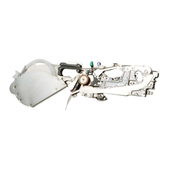
TAPE Feeder (ATF Type)
AF05/08, AN05/08
AQ02HP
INSTRUCTION MANUAL
Thank you very much for purchasing a product of our company.
CAUTION
Inquiry contact regarding the product :
CUSTOMER SUPPORT DEPARTMENT
ELECTRONIC ASSEMBLY SYSTEMS BUSINESS UNIT
ADDRESS : 2-11-1, Tsurumaki, Tama-shi, Tokyo 206-8551, JAPAN
PHONE
FAX
In order to ensure safe use of the TAPE Feeder, be sure to read this
Manual before using the machine.
After reading this Manual, keep it at a fixed location so that it will be
available at any time.
: 81-42-357-2218
: 81-42-357-2297
40028346
Rev.02
Advertisement
Table of Contents

Subscribe to Our Youtube Channel
Related Manuals for JUKI AF05


Summary of Contents for JUKI AF05
- Page 1 TAPE Feeder (ATF Type) AF05/08, AN05/08 AQ02HP INSTRUCTION MANUAL Thank you very much for purchasing a product of our company. In order to ensure safe use of the TAPE Feeder, be sure to read this Manual before using the machine.
- Page 2 (3) This manual is written as carefully as possible. However, if you have a question, or find a mistake or missing information, contact our dealers or JUKI Corporation. (4) JUKI Corporation is not responsible for any defects or malfunction due to your abnormal operation.
- Page 3 CAUTION For the safe operation of machinery All personnel engaged in the operation of the chip placer and its accessories (here after referred to as "machines") including the operators, service and maintenance personnel are required to read through this safety warning to make familiar with its handling to prevent accidents and injuries.
- Page 4 Matters of Caution Regarding Safety CAUTION Basic Matters of Precaution Be sure to read all documents included in this Manual and the attached booklet before using this machine. Also, keep this Manual carefully so as to be able to read it whenever necessary. Contents of this Manual include items that are not included in specifications of the machine purchased.
- Page 5 CAUTION Matters of Caution at Each of Its Use Stages Transport When lifting the machine or moving it, take sufficient safety measures so that no dropping accidents will occur. Keep the following environment when transportation or storage. Environment requirements Temperature : -15℃ to 70℃ Humidity : 20%...
- Page 6 Precautions for Using the Tape Feeder Safely According to the descriptions of Chapter 3 “Daily Inspection,” inspect, clean and lubricate the tape feeder regularly. Since the tape feeder is a precision device, never store it over another equipment or vice versa. Replace a tape on the designated working table.
-
Page 7: Table Of Contents
ATF Instruction Manual Table of Contents 1. Overview ..................... 1 1.1 Features ......................... 1 1.2 Specifications ......................... 1 1.3 Name of Each Part......................2 2. How to Use....................4 2.1 Attaching or Detaching the Tape Reel................4 2.1.1 How to attach the tape reel..................4 2.1.2 Removing a tape....................8 2.2 Carrying the Tape Feeder.................... -
Page 8: Overview
Parts feeding method Ratchet driven method Note 1: When a JUKI jig tape is used. Note 2: The pick-up position accuracy varies depending on the accuracy of the tape you use. Note 3: When you use a feeder bank for KE-750/760 or KE-2010/2020/2030/2040, or when you use an AN081C (for both paper and embossed tapes), you have to perform teaching operation depending on the thickness of a tape. -
Page 9: Name Of Each Part
ATF Instruction Manual 1.3 Name of Each Part 18 14 Figure 1.1 Section A Section B Figure 1.2 X-axis reference pin A Lock holder X-axis reference pin B Cross roller Upper cover Guide roller Upper cover hook Tape guide Knock lever Guide cover Shutter Reel support... - Page 10 ATF Instruction Manual Detailed figure of the section A Figure 1.3 Detailed figure of the section B Figure 1.4 X-axis adjustment shaft Lock holder Sprocket wheel Plunger plate Ratchet hook adjustment Toggle pressure adjustment lock pin eccentric collar Ratchet hook stopper Lock holder Y adjustment lock pin If you do not have any feeder inspection jigs, do not disassemble any parts.
-
Page 11: How To Use
ATF Instruction Manual 2. How to Use 2.1 Attaching or Detaching the Tape Reel 2.1.1 How to attach the tape reel 1) Push the upper cover hook in the direction indicated with the arrow mark to unhook the upper cover. Upper cover hook Figure 2.1.1 2) Lift the upper cover in the direction... - Page 12 ATF Instruction Manual 4) Thread the carrier tape through the path located on the feeder upper section (in the direction indicated with the arrow mark) (see Figure 2.1.6), and pull it out to the bottom of the upper cover. Then, thread the cover tape through the peel-off slit of the upper cover (see Figure 2.1.7), and close the upper cover.
- Page 13 ATF Instruction Manual 5) Thread the cover tape over the guide roller, cross roller, cross roller and guide roller in this order (①→ ② → ③→ ④) (see Figure 2.1.12) so that the tape cannot be twisted, and place the cover tape around the delivery roller while pushing the retaining roller arm in the direction indicated with the arrow mark to tuck the tape under the retaining roller (see Figure 2.1.11).
- Page 14 ATF Instruction Manual ● Setting a tape if the cover tape is short To wrap the cover tape around the delivery roller, the lead length must be approximately 300 mm or longer. If the length is shorter than 300 mm, splice the front edge of the lead section with adhesive tape to extend the length.
-
Page 15: Removing A Tape
ATF Instruction Manual 2.1.2 Removing a tape 1) Push the retaining roller arm in the direction indicated in the figure to remove a tape. Retaining roller arm Figure 2.1.13 2) Push the upper cover hook in the direction indicated in the figure to unhook the upper cover. -
Page 16: Carrying The Tape Feeder
ATF Instruction Manual 2.2 Carrying the Tape Feeder Grasp the grip section of the tape feeder securely to carry it. Grip section Section “A” Figure 2.2.1 • When carrying the tape feeder, do not grasp the section “A.” If any abnormal load is imposed on the section “A,”... -
Page 17: Splicing
However, you can use a tape on the market that satisfies the regulated requirements for some models indicated in Table 2.4.2 also. Table 2.4.1 Width JUKI specified tape part number E9031706AA0 Table 2.4.2 Model name Detailed requirements for tapes on the market... - Page 18 ATF Instruction Manual 3) After you pull the cover tape of a new component to the first component position to peel it off, cut the tape without with leaving one cavity in which any component is not located. Cover tape ①Pull the cover tape to the first component position to peel it off.
- Page 19 ATF Instruction Manual 6) Cover the end of the tape you are using with the front edge of the new tape, and paste the latter half of the splice tape over the cover tape securely. New tape Paste the splice tape only after Tape already used aligning the edge of the cut tape with the tape already used...
- Page 20 ATF Instruction Manual ● When you splice am embossed type of carrier tape When you splice an embossed type of carrier tape, use a joint tape after splicing tapes normally. It is useful to splice tapes stably. 1. Paste a joint tape over the carrier tape as shown in the figure below, and cut the pasted tapes so that the width can become approximately 3 mm.
- Page 21 ATF Instruction Manual ● Procedure for cutting the strongly adhesive cover tape If you use a cover tape whose adhesiveness is strong, a joint tape is peeled off from the cover tape, and it may jam the peeled-off cover tape. In such a case, follow the procedure below to splice the joint tape.
-
Page 22: Attaching Or Detaching The Tape Feeder Onto A Mounter
ATF Instruction Manual 2.5 Attaching or Detaching the Tape Feeder onto a Mounter 1) Check to see if there is no foreign substance such as an element on the fixed side of the tape feeder or upper surface of the mounter bank. Positioning hole of X-axis reference pin A Fixing plate... -
Page 23: Daily Inspection
ATF Instruction Manual 3. Daily Inspection 3.1 List of Daily Inspection Items Daily inspection items Frequency Every Action to Where to inspect and/or Every Every Every Once a Inspection item be taken adjust week month year months Inspection Upper cover - Check to see if there is no scratch or Inspect the upper cover when you install the flaw on the groove located on the bottom... -
Page 24: Where To Inspect
ATF Instruction Manual 3.2 Where to Inspect 1) Inspecting the upper cover Check to see if the peel-off slit located on the bottom side of the upper cover is not flawed or deformed. If the upper cover is flawed or deformed, replace it with a new one. (See the description on replacement of the upper cover on page 27 for how to replace the upper cover.) Shutter... - Page 25 ATF Instruction Manual 4) Inspecting the reference side (bottom side) for fixing the tape feeder Check to see if the fixing reference side (feeder bank connecting side) is not flawed or if no foreign substance is stuck to this side. If any foreign substance is stuck to this bottom side, use an air gun or similar device to remove it.
- Page 26 ATF Instruction Manual 7) Inspecting the cramp pressure Check to see if the lock release lever clicks (in the same manner those of other feeders click) when you attach the tape feeder onto the feeder bank and close the lock release lever. If the lock release lever does not click, make the following adjustments.
-
Page 27: Where To Clean
ATF Instruction Manual 3.3 Where to Clean 1) Cleaning the upper cover shutter Clean the slit section with IPA to remove adhesive substances and any other stains. Remove stains from the edge, groove and sliding surfaces of the shutter. Note: Grease is applied to the shutter pin section. Take care not to remove grease with IPA. - Page 28 ATF Instruction Manual 4) Cleaning the tape traveling section Clean any grease or debris that is generated when the carrier tapes slides from the tape traveling section. 5) Cleaning the cover tape eject section Use a dry cloth to rub the eject cover, inner guide, blade base and retaining roller blade if an adhesive substance is stuck to any of these parts.
- Page 29 ATF Instruction Manual ● Position for assembling the eject cover Adjust the eject cover assembling position so that it can be parallel with the blade base, the distance between the eject cover and the blade base can be 1.5 ± 0.3 mm, and the distance between the eject cover and the delivery roller (assembly) can be 1 ±...
-
Page 30: Where To Lubricate
ATF Instruction Manual 3.4 Where to Lubricate * In addition to the regular maintenance period, apply Albania grease to the ratchet wheel and/or free link section if grease is removed from either of these parts when you clean the tape feeder. 1) Ratchet wheel Apply Albania grease to each gum between teeth of the ratchet wheel. -
Page 31: Parts To Be Replaced Regularly
ATF Instruction Manual 3.5 Parts to Be Replaced Regularly 3.5.1 List of parts to be replaced regularly Part number Part name When to Remark replace (year) E1311706AA0 Deliver roller assembly You may have to replace the blade E1326706A00 Retaining roller blade if you use a PSA (pressure sensitive adhesives) cover tape. - Page 32 ATF Instruction Manual 3) Replacing the retaining roller blade ① Remove the setscrew of the eject cover, then the eject cover. ② Remove the setscrew from the retaining roller blade. ③ Remove the flush-head screw from the section “A” to disassemble the roller blade fitting section.
- Page 33 ATF Instruction Manual ● Assembling position of each part ① Blade base Adjust the blade base assembling position so that the minimum distance between the blade base and the outer circumference of the delivery roller can be 0.3 mm to 0.5 mm and the surface of the delivery roller blade can be brought inside of the outer circumference of the delivery roller by 0.15 mm to 0.35 mm when you rotate the delivery roller by 360 degrees.
- Page 34 ATF Instruction Manual 4) Replacing the upper cover Eccentric shaft setscrew (fixed from the top surface) Upper cover Upper cover hook Eccentric shaft Feeder base ① Unhook the upper cover to release the lock of the upper cover. ② Loosen the eccentric shaft setscrew to pull out the eccentric shaft, and replace the upper cover with a new one.
-
Page 35: Options
ATF Instruction Manual 4. Options This chapter describes the options that allow you to use this tape feeder easily. 4.1 Bar Code Tag This option allows you to paste a bar code mark onto the rear edge of the tape feeder. You can check the bar code easily even after you attach the feeder onto the feeder bank. -
Page 36: Embossed Tape Spacer
ATF Instruction Manual 4.2 Embossed Tape Spacer When you use a carrier tape for embossed components whose material is soft and fragile, the stability of the feeding or pick-up operation of the tape feeder decreases, and the component pick-up ratio may be lowered. In such a case, attach the embossed tape spacer on the bottom side of the carrier tape. -
Page 37: Joint Tape
ATF Instruction Manual 4.3 Joint tape Part number Width E9031706AA0 Note: The width of the cover tape should be 4.9 ± 0.1 mm according to the JIS (C0806-3:1999). If your cover tape exceeds this value, you have to use a joint tape appropriate for the cover tape. - Page 38 ◆ Revision record Rev. Date Revised locations Revision contents Remarks Nov.2004 First edition For AQ02HP Apr.2006 P1,10,17,24,27 Jul.2009 Revised...
- Page 39 ELECTRONIC ASSEMBLY SYSTEMS BUSINESS UNIT 2-11-1, Tsurumaki, Tama-shi, Tokyo 206-8551, JAPAN PHONE: 81-42-357-2293 FAX: 81-42-357-2285 http://www.juki.co.jp/ Copyright © 2004-2011 JUKI CORPORATION The specification and appearance may be changed without notice. All rights reserved throughout the world. 2011.04 Printed in Japan...
Need help?
Do you have a question about the AF05 and is the answer not in the manual?
Questions and answers