Sign In
Upload
Manuals
Brands
JUKI Manuals
Industrial Equipment
FX-3R
JUKI FX-3R Manuals
Manuals and User Guides for JUKI FX-3R. We have
1
JUKI FX-3R manual available for free PDF download: Maintenance Manual
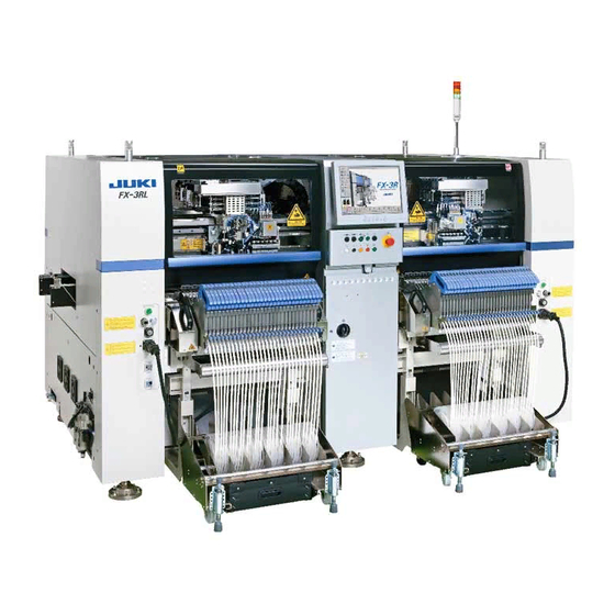
JUKI FX-3R Maintenance Manual (251 pages)
High-Speed Modular Mounter
Brand:
JUKI
| Category:
Industrial Equipment
| Size: 8 MB
Table of Contents
Table of Contents
3
X-Y Unit
9
Replacing the Magnescale
9
X-Axis Magnescale Affixing Position
10
Y-Axis Magnescale Affixing Position
11
Clearance of the Magnescale
12
Re-Obtaining the Parameters after Replacement of the Magnescale
12
Replacing the Limit Sensor and Origin Near Sensor
13
Replacing the X+/− Limit Sensor and X-Near Sensor
13
Replacing the y +Limit Sensor and YB-Near Sensor
14
Replacing the X-Axis Interference Sensor (Y-C Sensor)
15
Replacing the Cable Bear
16
Replacing the X-Axis Cable Bear
16
Replacing the Y-Axis Cable Bear
17
Replacing the Roller Lubrication Part
18
Head Unit
19
Replacing and Adjusting the Head
19
Replacing the Motor
25
Replacing the Z-Motor
25
Replacing the Θ-Motor
27
Replacing the Laser Sensor (LNC60)
28
Replacing the Head up Cylinder
29
Replacing the Belts
30
Replacing the Timing Belt Z
30
Replacing the Timing Belt Θ
30
Replacing the Z-Slide Shaft
31
Readjustment after Replacement of Head Unit
32
Parts Around the Head
33
Replacing the Solenoid Valves
33
Replacing the Filter
35
Replacing the Bad Mark Sensor
36
Sensor Assembly
36
Adjusting the Sensor Height
37
Amplifier
37
Assembling the Fiber Unit to the Amplifier
38
Amplifier Setting
39
Manual Setting Method for the F70R Fiber Sensor Amplifier
40
Replacing the HMS
41
Replacing the HMS Head
41
Replacing the Amplifier
41
Sticking the Label
42
Adjusting the HMS Height
42
Replacing the Head Board
43
Replacing the Head Main Board
43
Replacing the ZT-Driver Board
44
Occ Assembly
45
Replacing the OCC Assembly
45
Replacing the CCD Camera and Lens
46
Replacing the OCC Coaxial/Angle Light Board Assemblies
47
Replacing the Lens Filter
48
Adjusting the Focus
50
Adjusting the OCC Light Quantity
51
Replacing the Solder Recognition Light Board
52
Readjustment after Replacement of OCC Unit
53
Board Transport Unit
54
Replacing the Transport Belt
54
Replacing the Transport Pulley
55
Transport Pulley a Assembly: E21117150A0
55
Replacing the STATION, IN, OUT, and JOINT Motors
56
Replacing the in and out Sensors
57
Replacing the WAIT, STOP, and C-OUT Sensors
58
Replacing the Fiber
58
Replacing the Amplifier Unit
58
Adjusting the Sensitivity of the WAIT/STOP/C-OUT Sensor
60
Replacing the Stopper Cylinder
63
Replacing the Support Table Home Position Sensor (BU Home Position Sensor)
64
Replacing the T-PIN Sensor (Optional)
64
Replacing the Pusher y Cylinder (Outer Shape Reference)
65
Replacing the Centering Pin (Optional)
66
Replacing the Support Table Motor (BU Motor)
67
Adjusting the Gap between Torque Supporter and Support Motor
68
Adjusting the Tension of the Support Table Driving Timing Belt
68
Placing the Support Table Surface Horizontally
68
Replacing the Support Table ENC
70
Replacing the Backup Stopper (for en Type Only)
71
Auto PWB Width Adjustment
74
Replacing the AWC Motor
74
Replacing the AWC Origin Sensor
75
Replacing the Transport Stopper Interference Sensor
75
Replacing the Barcode Reader (On-Demand Production, Option for SCS)
76
Cal Block
79
Replacing the CAL Board Assembly
79
Atc
80
Replacing the Air Cylinder
80
Replacing the ATC OPEN and CLOSE Sensors
81
Adjusting the Speed Controller
82
Feeder Bank, Replacement Table and Electric Bank (Optional)
83
Common Parts and Units for Mechanical Feeder and Electric Feeder
83
Replacing the Bank-Up Cylinder
83
Adjusting the Speed Controller of the Bank-Up Cylinder (Optional Replacement Table)
84
Replacing the Bank-Up Detection Sensor (Optional Replacement Table)
84
Replacing the Selector Switch (Optional Replacement Table)
85
Replacing the Roller Lever (Optional Replacement Table)
85
Replacing the Cables and Connectors of Replacement Table (for Intelli Trolley)
86
Replacing the Antenna of the Replacement Table (for Intelli Trolley)
88
Bank and Replacement Table for Mechanical Feeder
90
Overall Drawing
90
8-2.2. Replacing the Drive Cylinder
91
Adjusting the Speed Controller of the Drive Cylinder
92
Replacing the Feeder Bank Board (Optional)
92
Replacing the Bank PCB
93
Replacement Table for Electric Feeder
94
Overall Drawing (Replacement Table for ETF)
94
Overall Drawing (Lifter Unit)
96
Replacing the Bank PCB
97
Replacing the Connector Cable
98
Replacing the Connector for Off-Line Setup
99
Replacing the ETF Incorrect Insertion Detection Sensor
100
Electric Fixed Bank (Optional)
103
Overall Drawing
103
Replacing the Outer Bank PCB and Connector Cable
105
Replacing the Connector for Off-Line Setup
105
Replacing the ETF Incorrect Insertion Detection Sensor
105
Pneumatic Units
106
Replacing the Digital Pressure Switch (Positive Pressure)
106
Adjusting the Digital Pressure Switch (Positive Pressure)
106
Replacing the Filter Element
108
Replacing the Digital Pressure Switch (Negative Pressure)
109
Adjusting the Digital Pressure Switch (Negative Pressure)
109
Switches
116
Replacing the Push-Button Switch
116
Replacing the EMERGENCY STOP Switch
117
Replacing the Cover Open Switch
118
Switch Main Unit
118
Operation Key
119
Replacing the Push-Button Switch (CE Marking Machine)
120
Replacing and Adjusting the Feeder Float Sensor
122
Other Units
130
LCD Monitor
130
Replacing the LCD Monitor
130
Setting up the Touch Panel (TECNART, TM150-JDA03)
131
Replacing the System Disk
133
Replacing the SSD
133
Setting up the BIOS
135
Setting up the Network (this Setup Is Required When Communicating with the IS.)
140
Installing the FX-3R System Programs and Flexline DB
150
Upgrading the FX-3R System Version
161
HUB-BOX (RFID Applicable Option)
166
Electrical Components
170
Layout of Electrical Components
170
Layout of Top of Base Frame
171
Power Supply Unit
172
Structure of Power Supply Unit
172
Control Unit
185
Structure of Control Unit
185
CPU Board (40107372)
186
Position Board (40044540)
187
Cpci-8994 Board (40048003)
188
ETHER-MAIN Board (40048066)
189
IP-X5 Board Assembly (40047528)
190
MOUSE/KEYBOARD Selector (40003281)
192
SUPERIMPOSE Board (40048082)
193
ATX Power Supply (40048006)
195
Battery Unit (40048007)
197
X-Y Unit
199
Structure of X-Y Unit
199
Z-Θ Unit
201
Structure of Z-Θ Unit
201
LED Indications
202
Transport Unit
203
Structure of Transport Unit
203
Adjusting the BASE-CARRY Board (40047559)
213
Adjusting the Stepping Driver
213
Head Unit
216
Adjusting the Boards of the Head Unit
216
Covers
218
Structure of Operation Unit
218
Jumper Switch Settings on the Operation Board Assembly
218
Mounting Switches Onto the Operation Switchboard
220
Replacing the Fuse of the AC Input Unit
227
Other Boards
228
FEEDER Board (40047560)
230
Adjusting the Dial of the Vacuum Pump Electromagnetic Switch
231
(Thermal Protector)
231
Feeder Position Indicator (Fpi)
232
Detaching the FPI (Front) from the Machine Main Unit
232
Tape Cutter (Optional)
235
Overall Drawing
235
Tape Cutter for Electric Fixed Bank Specification
236
Replacing the Tape Cutter Main Unit
237
Assembling and Adjusting the Lower Discharge Guide
242
Replacing the Movable Cutter Blade (Bottom Blade) of the Tape Cutter
244
Replacing the Fixed Cutter Blade (Upper Blade) of the Tape Cutter
246
Grease up
247
Fx-3R Jig Lists
248
Advertisement
Advertisement
Related Products
JUKI FX-1
JUKI FX-1R
Juki Exceed F-600
Juki Exceed F-400
Juki Exceed F-300
JUKI FLS-350NA
JUKI FLS-350NB
JUKI FLS-350N Series
JUKI FLS-351NA
JUKI 72005824
JUKI Categories
Sewing Machine
Industrial Equipment
Sewing Machine Accessories
Accessories
Measuring Instruments
More JUKI Manuals
Login
Sign In
OR
Sign in with Facebook
Sign in with Google
Upload manual
Upload from disk
Upload from URL