
Related Manuals for Lamtec FMS Series


Summary of Contents for Lamtec FMS Series
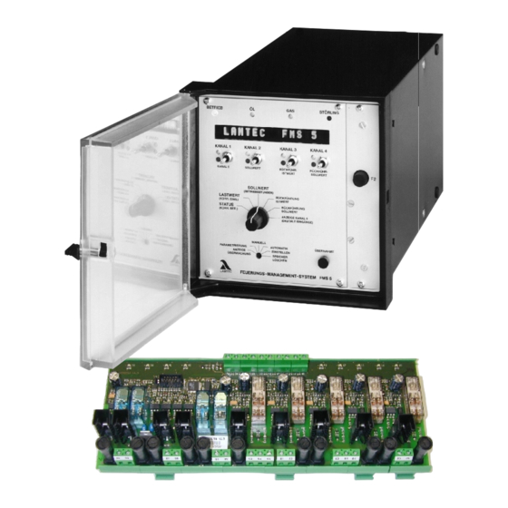
- Page 1 Commissioning FMS Firing Management System TÜV type-approval 0085 AS 0254 DIN DVGW Test mark NG-2510 AS 0324 Sensors and Systems for Combustion Engineering...
-
Page 2: Table Of Contents
Table of Contents Access levels General Information 5 - 15 Entering the password Validity of these instructions Changing password Standards Changing parameters For your safety List of parameters Follow the legislation on safety of appliances (level 0 and 1 parameters only) 21 - 29 Leakage test 30 - 31... - Page 3 Table of Contents Instrumentation for commissioning O regulation 49 - 62 Adjusting load ratings individually Automatic functions control Entering an initial curve during operation 49 - 50 Approaching control elements from one side Adjusting the integrated O regulator (optional) Entering settings Checks during burner start-up Entering top setting O monitoring bands...
- Page 4 Replacing a servomotor, for rev. speed monitoring replacing a potentiometer 124 - 125 Relay module Replacing a servomotor with LAMTEC connection diagram precalibration Type 660 R 0013 / Type 660 R 0131 Replacing a complete servomotor Type 660 R 0019...
-
Page 5: General Information
General Information Validity of these Instructions Validity of these instructions These instructions apply to the FMS 4 and FMS 5 Combustion Management System in any configuration. The software-related information relates to the software version V3.1 (recognisable from the sticker inscription on the program EPROM). Standards The units conform to the following standards and regulations: EN 298... -
Page 6: For Your Safety
LAMTEC GmbH & Co KG will not be liable for damage or injury arising out of a failure to observe the instructions above. The warranty and liability provisions of the terms and conditions of sale and supply of LAMTEC GmbH &... -
Page 7: Purpose
General Information Purpose Intended purpose The FMS 4 / FMS 5 Combustion Management System is a control unit for FMS 4 / FMS 5 combustion systems. Brief description The FMS 4 adjusts up to four control elements as a function of a control variable (generally the burner load) according to freely programmable curves. -
Page 8: Application-Internal Output Regulator (Optional)
General Information Purpose The FMS contains a burner control unit with process control program. Outputs: - actuation of gas valves - actuation of oil valves - actuation of the ignition valve and ignition transformer - fan release - oil pre-heating - fault signal - signal outputs for oil and gas operation (in the off condition, oil operation is always indicated) -
Page 9: Using These Instructions
General Information Using these instructions Purpose of these instructions These instructions are concerned exclusively with commissioning and servicing. Further information, for example design examples, possible uses, software settings etc., is given in separate booklets. Special information dealing with optional equipment on this unit is explained in separate booklets. -
Page 10: Fault Correction
___________________________________________________________________ Tip: You can download the up-to-date version of these instructions from http://www.lamtec.de as PDF File. You will find the version from the letter of the booklet no. (see the backside of this document). Example: DLT 6066 cD booklet No. -
Page 11: Fms Operating Principle
General Information FMS Operating Principle FMS Digital Inputs For the FMS to function according to the requirements of a combustion system, the condition signals from the system must be relayed to the FMS. These signals include: Pre-ventilation suppression Air pressure monitor Gas safety interlock circuit Gas pressure >... -
Page 12: Through An External Signal
General Information FMS Operating Principle Start without pilot burner: The main valves open and remain activated together with the ignition transformer for the duration of the safety period. During this time the flame signal appears. Start with pilot burner: The ignition valve and main gas 1 are opened. The pilot flame forms and the flame signal appears. -
Page 13: Setting The Pilot Burner, Serving Mode
General Information FMS Operating Principle A so-called servicing mode can be set via parameters. The control unit then Setting the pilot burner, runs until the stabilisation period. In this mode 5 successive starts are servicing mode possible without the need for pre-ventilation and without a leakage test. The 5 start is automatically followed by pre-ventilation and/or a leakage test. -
Page 14: Internal Load
General Information FMS Operating Principle Internal load The internal load is the load value at which the compound currently stands. It therefore corresponds indirectly to the output of the burner. The internal load is displayed in addition to the external load signal. In the "load value”... -
Page 15: Energy-Saving Mode For Running Text Display
General Information FMS Operating Principle Energy-saving mode for The brightness of the display can be adjusted to the ambient light running text display conditions by means of parameters. In addition the display can be set to automatically revert to the lowest brightness level if not operated within a given period of time. -
Page 16: Settings
Settings Inputs Significance of ID number The ID number comprises 8 characters, e.g. 664 V 0010 The two figures before the letter denote the unit, in this case a FMS 4. The letter denotes whether the unit is a VMS or a FMS. The penultimate figure provides information on the unit hardware. -
Page 17: Condition On Delivery
Settings Condition on delivery Condition on delivery All units are set according to the order. Settings not evident from the ID number or configuration number must be indicated separately. In particular: Outputs - whether continuous or three-point step - whether 0 … 10 V, 0/4 … 20 mA - position of the outputs in the event of fault Inputs, load, feedback - Whether potentiometer or 0/4 …... -
Page 18: Processor Card
Settings Condition on delivery Processor card Sockets for contiuous additional cards Configuration Channel 1 Channel 2 Channel 3 Channel 4 80 C 537 Note: Continuous channels must all be fitted with additional cards from channel 1 onwards Power supply card Fuse 2 1 AT mA Transformer... -
Page 19: Parameters
Production levels (Levels 3 and 4) Access to all parameters (only possible through LAMTEC) Each parameter level is protected by its own checksum. This checksum serves to show that no changes have been made (see page 78). -
Page 20: Changing Password
Turn selector switch (1) to Digital inputs Press the Acceptance key (3) - new password is set x x x x x x LAMTEC LAMTEC Changing parameters Select the required parameter with Channel 3 key Change its value with Channel 4 key... -
Page 21: List Of Parameters
Settings List of Parameters (Level 0 and 1 parameters only) When changing the parameters via interface (by means of optional PC software) a check must then be made on the spot to ensure that the changes have been properly accepted. This can be done by reading out the parameters on the unit or by comparing the unit's checksums. -
Page 22: List Of Parameters (Level 0 And 1 Parameters Only)
Settings List of Parameters (Level 0 and 1 parameters only) Para- Short Safety Lower Upper meter- design- level limit limit Standard nation Description values Aids _____________________________________________________________________________________________________ Correction K1 Spreiz Spread factor for correction input (00.0 99.9) 01.0 = no expansion K2 Spreiz Spread factor for correction input (00.0 99.9) 01.0 = no expansion... -
Page 23: List Of Parameters
Settings List of Parameters (Level 0 and 1 parameters only) Para- Short Safety Lower Upper meter- design- level limit limit Standard nation Description values Aids _____________________________________________________________________________________________________ Unt.Mo5 Monitor output, curve set 5: 4 mA correspond to X points Unt.Mo6 Monitor output, curve set 6: 4 mA correspond to X points Unt.Mo7 Monitor output, curve set 7:... -
Page 24: List Of Parameters
Settings List of Parameters (Level 0 and 1 parameters only) Para- Short Safety Lower Upper meter- design- level limit limit Standard nation Description values Aids _____________________________________________________________________________________________________ BandV K4 Band shift Channel 4 BandV K5 Band shift Channel 5 Compound Laufz L 65535 Running time in pts./min for TPS 9999... -
Page 25: List Of Parameters
Settings List of Parameters (Level 0 and 1 parameters only) Para- Short Safety Lower Upper meter- design- level limit limit Standard nation Description values Aids _____________________________________________________________________________________________________ ES aktiv ES is activated when load falls by X points Verz. ZÜ Delay time of ignition position relay Verz. -
Page 26: List Of Parameters
Settings List of Parameters (Level 0 and 1 parameters only) Para- Short Safety Lower Upper meter- design- level limit limit Standard nation Description values Aids _____________________________________________________________________________________________________ SoftStop Soft stop time Burner after running Soll1min 1000 Control unit setting 1 minimum with atmosphere control/control unit setting 1 Soll1max 1000... -
Page 27: List Of Parameters
Settings List of Parameters (Level 0 and 1 parameters only) Para- Short Safety Lower Upper meter- design- level limit limit Standard nation Description values Aids _____________________________________________________________________________________________________ Leist. 1 1000 Power output of burner with curve set Leist. 2 1000 Power output of burner with curve set Leist. -
Page 28: List Of Parameters
Settings List of Parameters (Level 0 and 1 parameters only) Para- Short Safety Lower Upper meter- design- level limit limit Standard nation Description values Aids _____________________________________________________________________________________________________ Einh. Kan.3 Represented unit channel 3 Einh. Kan.4 Represented unit channel 4 Einh. Kan.5 Represented unit channel 5 R4mA K1 4 mA feedback corresponds... -
Page 29: List Of Parameters
Settings List of Parameters (Level 0 and 1 parameters only) Para- Short Safety Lower Upper meter- design- level limit limit Standard nation Description values Aids _____________________________________________________________________________________________________ Parameter for O regulation O2Regler O -Regulator 0 = O regulator off 8 = Only display, base value 1 = Standard regulator for deact. -
Page 30: Leakage Test
Leakage Test Mode of Operation Integrated Leakage Test (option) Leakage test flow chart Integrated leakage test The leakage test checks whether the main gas valves are leak-tight. (option) The supply gas pressure is used for this purpose. Since the leakage test line (space between the two main valves) burns empty in the event of a shut-off, this part is normally pressureless when starting (gas pressure >... -
Page 31: Venting
Leakage Test Venting Leakage test line over roof Calculation formula An (approximate) formula for calculating the leak test facility is compiled below: Definitions: gas pressure monitor gas-side safety shut-off device burner-side safety shut-off device barometric air pressure 1000 mbar » lower switch point (falling) of GDW upper switching point (rising) of GDW switch difference of GDW... -
Page 32: Output Regulator (Optional)
Output regulator (optional) Method of operation Procedure description The burner's startup proceeds exactly as already described, except that an enabling command to start the burner must have been provided by the output regulator. In other words, the actual value must be smaller than the set-point by an appropriate amount. -
Page 33: Output Regulator (Optional)
Output regulator (optional) Method of operation Set-point switch-over The set-point can be switched over via a digital input. In versions with a fixed set-point, this contact can be used to select between the two values entered in the parameters list. If, in addition, weather control is activated, a selection is made between two pairs of limiting values (see Weather control and Limiting ranges). -
Page 34: Output Regulator (Optional) Method Of Operation
___________________________________________________________________ In manual mode, the load regulator's functions such as startup circuit and control thermostat are switched off therefore always monitor the system continuously when using manual control. ___________________________________________________________________ x x x x x x LAMTEC LAMTEC... -
Page 35: Setting The Regulator
Output regulator Setting the regulator Interpreting the display The display when "Load” is selected Set-point Actual value Load specification Internal load The display in manual operation Load Internal load Actual value specification (via Channel 1 key) Setting the output regulator The output regulator is only adjusted via the parameters. -
Page 36: Regulator Behaviour
Output regulator Setting the regulator Regulator behaviour The load regulator attempts to adjust the actual value to the set-point. A direct relationship between the internal load and the boiler's temperature is assumed. In other words, the higher the internal load, the faster the boiler's temperature rises. - Page 37 Output regulator Setting the regulator Example Load specification Max load Set-point Distance from set-point 10 points Actual value Readjust- ment interval 10 s Parameters set in this example: P-factor I-factor D-factor Time Deviation from set-point Change in actual value P-fraction I-fraction -9,5 D-fraction...
-
Page 38: Examples
Setting the regulator Output regulator Regulator behaviour All three fractions (P-fraction, I-fraction, D-fraction) are added together and act as an adjustment to the compound regulator's load specification. The value is added to the momentary internal load. As long as the actual value is below the set-point, the P-fraction and the I-fraction are positive, i.e. -
Page 39: Before Commissioning
Before commissioning Adjusting motor As soon as the FMS is supplied with voltage, it attempts to drive the actuator limit switch motors to the lower boundary of the factory curve. If the end-bearing's limit switches are not properly adjusted for this then the motor may hit the actuator's mechanical stop. -
Page 40: Fms Commissioning
Selector switch (1) to "Status” "OFF” appears on the display Selector switch (1) to "Load rating” x x x x x x The following appears: LAMTEC LAMTEC - for external load default » - for internal load control unit »... -
Page 41: Significance Of Fmsdigital Input Display
FMS Commissioning Set selector switch (1) to "Status” Aids Press Acceptance (3) (and keep pressed) - the instantaneously set correction range appears - KB appears between the channels On a 4-channel unit: Selector switch (1) to "digital inputs” On a 5-channel unit: Selector switch (1) to channel 5 display Press Acceptance (3) - the condition of the digital inputs appears... -
Page 42: Setting Control Elements
FEEDBACK “ EI” appears on the display SETTING x x x x x x LAMTEC LAMTEC Set "Lower stop” x x x x x x Set the channel's target value to "0” via key (4) Red LED (B) comes on Actuator responds e.g. -
Page 43: Programming Curves
ENTER indicated. Otherwise the unit registers a fault and/or will accept no x x x x x x LAMTEC LAMTEC inputs. It may be necessary to wait for the automatic firing sequence control to release the control before programming with the burner running (via mode "EV”, "EZ”, "EG”). -
Page 44: Programming 1 Point
Mode selector switch (2) to "Setting” "EI” appears in the middle of the display SETTING x x x x x x LAMTEC LAMTEC x x x x x x Selector switch (1) to "Set point” Switch (4) up or down... -
Page 45: Programming 2 To 19 Point
Selector switch (1) to "Actual value feedback” Wait until feedback has stopped ÜBERNAHME x x x x x x LAMTEC LAMTEC Press Acceptance (3) Point X appears on the display (X is the number of the programmed point. That is, at the 4 press of the... -
Page 46: Programming Last Top Point
MEMORY ENTER set point and actual value feedback are displayed. x x x x x x LAMTEC LAMTEC FEUERUNGS-MANAGEMENT-SYSTEM FMS Switch (4) (channel 2) up or down until channel 5 is optimally adjusted Selector switch (1) to "Actual value feedback”... -
Page 47: Adding Points
SETTING On FMS 5: Selector switch (1) to "Channel 5 display” x x x x x x LAMTEC LAMTEC set point and actual value feedback are displayed. Switch (4) (channel 2) up or down until channel 5 is optimally adjusted Selector switch (1) to "Actual value feedback”... -
Page 48: Changing Curve Point
Selector switch (1) to "Channel 5 display” set point and actual value feedback are displayed. x x x x x x LAMTEC LAMTEC Switch (4) (channel 2) up or down until channel 5 is optimally adjusted Selector switch (1) to "Actual value feedback”... -
Page 49: O Regulation
FMS Commissioning O regulation Automatic functions control during operation Adjusting the integrated This section explains only the operating steps needed to input the O curve. O regulator (optional) Further information on O regulation is contained in the publication DLT 5002.99cD Commissioning Supplement for the Optional "Integrated O Regulator”. -
Page 50: Dynamic Probe Test
FMS Commissioning O regulation Automatic functions control during operation The monitoring bands can be parameterised for 2 fuels, oil/gas, referenced to each fuel (parameters 923 to 934). In the case of more than 2 curve sets, these can be assigned to the individual curves via the parameters 912 and 913. -
Page 51: Regulation Strategy
FMS Commissioning O regulation Regulation strategy The regulation strategies employed were specially developed and optimised for the circumstances prevailing in combustion facilities: - Frequent output changes, - long lag times. During burner start-up, the O regulator remains on standby until it is ensured that plausible O measured values are being displayed. -
Page 52: With Pre-Setting For Load Changes
O regulation FMS Commissioning Regulation strategy O regulation by means of a comparison between target and actual values is With pre-setting for load changes (standard regulator) only performed if no output change (load change) takes place ("internal load” static). After a preceding load change, an target/actual value comparison is performed and an actuation step triggered only after expiry of the set lag time (parameters 898 and 900). -
Page 53: Extended Regulation Strategy (Air Shortage)
FMS Commissioning O regulation Regulation strategy Parameter 896 can be used to select whether the pre-setting is always (at each load change) to be activated (factory setting Standard 1), or not activated (content 2). Furthermore, the updating too can be turned off. It is then possible to select whether, at load changes, the neutral correction value or the "Base value without regulator”... -
Page 54: Via Analogue Interface
Only O meters whose t response time is < 15 sec may be connected. Release of the analogue interface is only possible at the factory. (Cat. no. 663 R0030). In case of doubt, please contact LAMTEC. Range compensation via parameters 919 and 920 Factory setting: 4...20 mA ^ 0...25.0 vol. % O... -
Page 55: Operator Controls And Display
MONITORING DISPLAY DISPLAY CLEAR CLEAR MEMORY MEMORY ENTER ENTER LAMTEC LAMTEC LAMTEC LAMTEC Feuerungs-Management-System FMS Feuerungs-Management-System FMS Push channel key 3 downward to return to VMS/FMS mode. Note: O actual and target values are only displayed if O regulation or O display are activated by means of parameter 896. -
Page 56: Calling Up O Regulation Text Messages
- Call up text messages by pressing the Acceptance key (3). O2 - regulation active - Back press the Acceptance key (3) again, or turn selector switch (1) to a different position. x x x x x x LAMTEC LAMTEC... -
Page 57: Commissioning
FMS Commissioning O regulation Commissioning irst adjust the electronic compound completely. The integrated O regulator remains deactivated. Set parameter 896 to 0 "No regulator” or 3 " Only display ”. Setting the correction The integrated O regulator is connected inline and upstream of the range and correction mode FMS, as a free-standing program block. - Page 58 Vol.% O Typical O target value curve x x x x x x LAMTEC LAMTEC 1000 Load Note: The O target values can only be stored in the programmed load points. If load points are skipped, the line in between is interpolated.
-
Page 59: Calling Up The Correction Range Set
This function can be switched off via the parameter 0 - Release level 2. Content 0 Z off! x x x x x x ___________________________________________________________________ LAMTEC LAMTEC Calculation and setting of control parameters - Manual Run burner on low load. -
Page 60: Lag Time (Parameters 898/900)
FMS Commissioning O regulation Commissioning Lag time Parameters 898 / 900 New O target value [vol.%] Old O target value Actuation step Regulation parameter setting t ___ t = regulation section's lag time Specified via parameters 898 and 900 The calculated value should be input by means of parameter 898. Factory setting: 15 seconds. -
Page 61: Calling Up The Base Value For O Regulation
FMS Commissioning O regulation Commissioning Setting a base value for Perturbation of O regulation causes it to deactivate, and the specified "Deactivated regulator” correction value for "Deactivated O regulator” or "Air shortage” is output, and "Air shortage” depending on the cause. The burner is not shut down. Parameters 901/902 Parameter 897 can be used by the customer to specify a burner shut-down if 917/918... -
Page 62: Operation
O regulation deactivated (perturbed), e.g. test routines failed during burner start-up, dynamic test negative, O regulation temporarily deactivated for over 1 hour etc. x x x x x x LAMTEC LAMTEC Resetting od: Manually Switch to "O regulation” mode. Press the Acceptance key and call up error text. -
Page 63: Correction
FMS Commissioning Correction Set correction input If corrective intervention is desired: Aids Make sure that correction input is set Correction signal: terminals 27 and 29 (correction input 1) or Correction signal: terminals 33 and 34 (correction input 2) The correction is set via the parameter numbers 429-676, of which, however, only a fraction are generally released for use by the person commissioning. - Page 64 Correction FMS Commissioning Factory setting: Expansion factor 10; ^ 1.0, i.e. no weighting Expansion factor > 10; the correction increases with rising burner output; Expansion factor < 10; the correction decreases with rising burner output. For details see VMS Commissioning instructions, under Auxiliaries, p. 30. 100 % Fuel actuator Expansion...
-
Page 65: Setting The Correction Range
If the correction cannot extend the adjustment travel because a channel does not reach the range limit determined for pre-ventilation, the burner output is increased or reduced until x x x x x x the correction can be extended. LAMTEC LAMTEC _________________________________________________________... -
Page 66: Altering The Correction Range
FMS Commissioning Correction ___________________________________________________________________ Altering the correction range The parameters must be changed to allow the correction range to be altered. These parameters are accessible via Customer level (Level 1). ___________________________________________________________________ Proceed as described under Parameter setting. The values associated with the correction range are stored in parameters 517 and 597. -
Page 67: Run To Shut-Off Limits
FMS Commissioning Run to shut-off limits Run to shut-off limits As each monitoring system the FMS has tolerances, which affect the adjustment precision. With the FMS these tolerances can be affected by parameter settings. If the firing system is adjusted, it has to be ensured that also the flame burns reliably and stably in consideration of these tolerances. -
Page 68: Checking The Shut-Off Limits At The
Reset set-point value (4) to the next continuous channel in air deficiency direction. Check firing x x x x x x LAMTEC LAMTEC Repeat, until all continuous channels are checked at their limits. ___________________________________________________________________ If a correction affects the continuous channel, the test can be omitted, if the correction range is bigger than the adjusted monitoring band (what is ordi- narily the case). -
Page 69: Tolerance Limits Direction Air Deficiency
FMS Commissioning Run to shut-off limits The correction value can now be changed at will with Channel key 1 (6), with burner on. The manually selected correction value is maintained until the selector switch (2) is turned to some other position, or normal correction is activated by pressing Channel key 2 (4) downward. -
Page 70: Example Protocol
IFMS Commissioning Run to shut/off limits Example protocol for the evidence of the parameter settings of the monitoring bands Protocol Monitoring band, Dead band and correctional settings FMS date serial no. system operational mode: tolerances to air deficiency side Channel Functions Dead Band Monitoring Band Band Shift... -
Page 71: Tips & Tricks
"Adding points” on page 47. SETTING ________________________________________________________ x x x x x x LAMTEC LAMTEC Mode selector switch (2) to "Setting” "EI” appears in the middle of the display Selector switch (1) to "Load rating” Run to ignition load point by means of channel 1 switch (4) D1, D2, Selector switch (1) to "Set point”... -
Page 72: Programming With Burner Stationary
EEPROM. The last valid EEPROM curve is therefore re-activated. ___________________________________________________________________ x x x x x x LAMTEC LAMTEC Instrumentation When commissioning systems with the FMS it is recommended that several for commissioning 5K potentiometers with ready-made connections and at least 2 current transmitters be always carried, (particularly where the continuous outputs are used). -
Page 73: Adjusting Load Ratings Individually
FMS Commissioning Tips & Tricks Adjusting load ratings individually - when load points are to be adjusted without programming a complete curve ___________________________________________________________________ When adjusting individual points it is normally only possible to freely adjust the set-point values. This is done by running to the load value (figure appears after the value). -
Page 74: Approaching Control Elements From One Side
FMS Commissioning Tips & Tricks _______________________________________________________________ Approaching control During operation the compound approaches the control elements from one elements from one side side in order to compensate for the mechanical hysteresis of the valves, approaching all set-points from above. Exception: The top point is never overrun and therefore approached from below. -
Page 75: Entering The Compound Curves With The Burner Stationary
FMS Commissioning Tips & Tricks Entering the compound curves ___________________________________________________________________ with the burner stationary In order to be able to program the FMS without a flame, the fan must be in operation (at least where a speed-controlled fan is actuated by the FMS) ___________________________________________________________________ Apply 230-V signal to fan - e.g. -
Page 76: System Operation
System Operation Mode Display Significance of modes Abbreviation Mode on the FMS "Switch-on sequence” "Ready" ZÜ “Ignition position” "Setting/Ignition position" "Base load” "Setting/Base load” "Post-ventilation" "Off" "Setting” "Clear memory" " Setting/Pre-ventilation" "Setting/Control" "Fault" "Pre-ventilation" HA or HAND "Manual mode" "Load extern" (RG) keine Anzeige "Control mode”... -
Page 77: O Regulator Modes
System Operation Mode Display indicates that although the mode selector switch is on "Setting”. its control function is working according to a calculated curve in the RAM. The curve is calculated from a partial curve already entered. This mode is arrived at if the burner is switched off during a programming sequence and then restarts. -
Page 78: Es" Mode Progress (Set-Control)
System Operation Mode Display "ES" Mode Should the burner skip to "ES" mode whilst programming is in progress (set - control) ___________________________________________________________________ This mode allows the electronic compound to run within curve sections already entered and thereby facilitates setting. If the load drops by 40 points, the FMS skips to "ES" mode, thereby controlling the outputs automatically. -
Page 79: Curve Sets Fms (Option)
System Operation 4 Curve sets FMS (option) Interconnection with The FMS offers the optional facility for using 4 curve sets. 4 curve sets option In this case 2 curve sets are firmly assigned to oil operation and 2 curve sets to gas operation. -
Page 80: Checksums Running Time Meter
CRC 16 of level 0: adjustable without password 1: adjustable by person commissioning 2: adjustable by burner/boiler manufacturer 3: adjustable only by LAMTEC 4: adjustable only by LAMTEC 1 oil safety time in seconds 2 oil safety time in seconds... -
Page 81: Messages / Faults
- associated running time meter reading appears on display In this way the fault history can be browsed through by x x x x x x LAMTEC LAMTEC operating the channel 1 switch ___________________________________________________________________ If you are sure that there has been a voltage on the FMS at all times since the last fault, the time of the fault can be determined by means of the current running time meter reading and the current time. -
Page 82: O Regulation Perturbed
MONITORING SETTING DISPLAY CLEAR MEMORY ENTER LAMTEC LAMTEC Feuerungs-Management-System FMS Air shortage perturbation If the actual O value is significantly smaller than the target value and corrective action by the FMS/VMS cannot rectify this error, the regulator is deactivated and the base value for air shortage errors is output. If desired, an air shortage burner shut-down can be triggered by the FMS/VMS. -
Page 83: Fault Codes
System Operation Messages / Faults ________________________________________________________________ Fault codes An "H” before the fault code indicates that the main processor has identified the cause of the defect. A preceding "Ü" indicates that the monitoring processor has triggered the fault. ________________________________________________________________ An * next to the fault code means that the control unit will attempt restarting after a few seconds. - Page 84 System Operation Messages / Faults Fault code number Aids H / Ü 143 Potentiometer defect, feedback varies too rapidly: channel 3 H / Ü 144 Potentiometer defect, feedback varies too rapidly: channel 4 H / Ü 145 Potentiometer defect, feedback varies too rapidly: channel 5 H / Ü...
- Page 85 System Operation Messages / Faults Fault code number Aids H / Ü 191* 1 monitoring band exceeded for too long: channel 1 B1,B3 H / Ü 192* 1 monitoring band exceeded for too long: channel 2 B1,B3 H / Ü 193* 1 monitoring band exceeded for too long: channel 3 B1,B3...
- Page 86 System Operation Messages / Faults Fault code number Aids H / Ü 321* Wire break feedback channel 1 H / Ü 322* Wire break feedback channel 2 H / Ü 323* Wire break feedback channel 3 H / Ü 324* Wire break feedback channel 4 H / Ü...
- Page 87 System Operation Messages / Faults Fault code number Aids Internal comparison: relay output terminal 76 does not pull on A19, A7 Internal comparison: relay output terminal 67 does not drop out A19, A7 Internal comparison: relay output terminal 43 does not drop out A19, A7 Internal comparison: relay output terminal 16 does not drop out A19, A7...
- Page 88 System Operation Messages / Faults Fault code number Aids Ü 713 Incorrect signal combination in AU mode Ü 714 Incorrect signal combination in BE mode Ü 715 Incorrect signal combination in VO mode Ü 716 Incorrect signal combination in ZP mode Ü...
- Page 89 System Operation Messages / Faults Fault code number Aids Ü 746 Solenoid valve cur-out defective Ü 747 Leakage test: venting into boiler not permitted Ü 750 Fault cut-out via the BUS Ü 751** No data transfer via BUS (time-out) Ü 760 Fuel change not permitted during adjustment Ü...
-
Page 90: Fms Fault Correction Aids
FMS Fault Correction General Faults (A) Aids Display remains dark Check whether there is a voltage present on the unit all LEDs are off Check "F1" fuse (back of the unit in cold unit case) Check connectors for correct seating _____________________________________________________________________________________________________ Display remains dark After changing an EPROM or RAM... - Page 91 Fault 110 The program EPROM may be defective. Request a new program EPROM from, LAMTEC, giving precise details of the order number and contract number at the time, the agent's order and all software checksums for the FMS. Please always return the defective EPROM (for address see back cover of this booklet).
- Page 92 The unit supplied possibly did not correspond to the order. displayed does not match the Consult LAMTEC. (For address see back cover of this booklet) or since the number on the configuration sticker. time of delivery the program EPROM has been changed and the new checksums were not noted.
- Page 93 FMS Fault Correction General Faults (A) Aids The FMS checks the function of all connected relays on the external modules. Fault The voltage present on the relay coils is read back. Possible causes: - Relay module not connected or connected wrongly Relay or relay module defective External voltage is fed into the corresponding terminal Terminal 9 and terminal 10 reversed...
- Page 94 FMS Fault Correction General Faults (A) Aids Fault Although terminal 9 and 10 both have +24V they are nevertheless monitored by internal tests at different times. They must not be connected to one another. Use terminal 9 only for supplying digital input signals. Use terminal 10 only for the supplying the relay modules.
-
Page 95: Three-Point Step Control Output (B)
FMS Fault Correction Three-point step control output (B) Aids Motor does not move Check whether "OPEN" and "CLOSE" relays pull on when the switch (4) is operated. If not: Make sure that there is not a fault (recognisable from the fault LED) Check F2 fuse (on power supply front panel) Check FMS relay-module connection If so:... - Page 96 FMS Fault Correction Three-point step control output (B) Aids Fault 2 monitoring band fault appears sporadically during operation. Cause: Motor is possibly running in wrong direction this may happen on capacitor motors if: - the capacitor is defective - there is a broken wire in the motor or in the lead _____________________________________________________________________________________________________...
-
Page 97: Continuous Output (C)
FMS Fault Correction Continuous output (C) Aids Control element does not react Measure continuous output in order to make sure that the FMS is Changes to continuous output working correctly. of the FMS Check output circuit to the control element ___________________________________________________________________ It is recommended that the FMS output signal be simulated with current transmitter, making it very easy to locate the fault. -
Page 98: Load Signal (D)
FMS Fault Correction Load signal (D) Aids Load signal does not show Cause: load transducer not on minimum the minimum value Run transducer down manually _____________________________________________________________________________________________________ Load signal cannot be changed Check whether fault present if so Rest fault (selector switch on status switch up) if not Check load circuit If only "000"... - Page 99 FMS Fault Correction Load signal (D) Aids Load rating does not attain If the load transducer is in the maximum position but does not emit the the highest value indicated highest possible value. Make sure that this position of the load transducer is the highest load rating position that occurs in operation.
-
Page 100: Feedback (E)
VMS Fault Correction Feedback (E) Aids A minimum value is not displayed in On feedback via potentiometer: "Actual value” position and "AU” display Cause: potentiometer connections transposed Check terminals Cause: Potentiometer incorrectly fitted to the motor shaft Turn potentiometer with control element connected until the desired value is displayed. - Page 101 FMS Fault Correction Feedback (E) Aids The feedback values displayed If the feedback element in its normal position is not at the bottom stop, do not correspond to the a higher feedback value may also be displayed. values indicated (e.g. in feedback of the fan speed minimum speed Make sure that the control element is in the normal position.
- Page 102 FMS Fault Correction Feedback (E) Aids E11 - Continued If the actual value is outside the 2 monitoring band, there is an immediate shutdown (3 sec.). Check control element, actuation and feedback. A relay may be "sticking”, the system may not have been in the starting position when starting (all channels closed) The motor is possibly defective (direction of rotation reversed) _____________________________________________________________________________________________________...
-
Page 103: Feedback (E)
FMS Fault Correction Feedback (E) Aids _____________________________________________________________________________________________________ Fault Only with "flying curve switching” option ___________________________________________________________________ With the flying curve switching option the 2 monitoring band is replaced by running direction monitoring for up to 30 seconds after switching over. This tests whether the control element is moving towards the new set-point value. -
Page 104: Correction Input (F)
FMS Fault Correction Correction input ( F ) Aids ___________________________________________________________________ Fault The monitoring processor checks whether the present correction values lies within the range set. ___________________________________________________________________ Check correction range Otherwise A7 _____________________________________________________________________________________________________ Fault Correction input is configured for 4 … 20 mA, but the instantaneous value is <... -
Page 105: Correction Input (F)
FMS Fault Correction Correction input ( F ) Aids ___________________________________________________________________ Message The correction signal is monitored in order to be able to detect an error function "Correction effect switched of the correction signal source (in O regulation). If a correction signal >97% is off, since over 97% for present on the input for 1 hour a defect is assumed and the correction longer than 1 hour”... -
Page 106: Digital Inputs (G)
FMS Fault Correction Digital inputs ( G ) Aids Fault The curve set was changed during operation Check wiring Especially the activation of terminal 75 ___________________________________________________________________ Even if the "flying curve switching” software option is activated on the FMS, allowing the curve set to be changed during operation, it must be remembered that in "EI”... -
Page 107: Control Unit Faults (H)
FMS Fault Correction Control Unit Faults (H) Aids The control unit has locked up Fault 600 - call-up running text and follow instructions there Check wiring and external signal transmitters e.g. safety interlock chain boiler safety interlock chain gas air pressure monitor safety interlock chain oil (special function) fuel selectionl (special function) external high firing rate acknowledgement... -
Page 108: Leakage Test
FMS Fault Correction Leakage Test ( I ) Aids If after the expiration of the duration, whichis set in P789 (after burner time) Fault 743 a flame signnal is recognized, these fault shut down occurs. You may set the monitoring time in P789. _____________________________________________________________________________________________________ Despite pre-ventilation, gas pressure is still/again present in the leakage test Fault 601... -
Page 109: Parameters (P)
FMS Fault Correction Parameters ( P ) Aids This parameter determines whether or not the compound control unit works Parameter 4 with separate ignition point and whether the load default is set automatically (level 2) during setting. (See Tips & Tricks) _____________________________________________________________________________________________________ This determines whether the band shift in the event of a change in power Parameter 707... - Page 110 FMS Fault Correction Parameters ( P ) Aids The correction range in points is entered here. Since the possible entries Parameters 517 to 676 range from 0 999 it is possible to program a horizontal to a channel and to run it entirely via the correction input.
- Page 111 FMS Fault Correction Parameters ( P ) Aids If the respective channel is configured as continuous output, this setting can Parameters 719 to 723 determine how rapidly this output must achieve the maximum adjustment. The time set here, however, is only a minimum running time. Due to the compound routine it may happen (for example, when using even slower damper drives on another channel) that this time is clearly exceeded.
-
Page 112: Parameter (P)
FMS Fault Correction Parameters ( P ) Aids This parameter is used to configure the burner for post-ventilation. Parameter 758 If the time is set to "0”, no post-ventilation occurs. _____________________________________________________________________________________________________ This serves for entering how many seconds the ignition position relays are Parameter 755 delayed after detection of the ignition position by the compound (or ignition on the FMS is released). - Page 113 FMS Fault Correction Parameters ( P ) Aids The network address for the respective serial interface is given here. The Parameters 826, 827 network address in the unit's delivered state is "0”. The network address is to be altered only where several units are polled via a BUS. If a network address other than "0”...
- Page 114 FMS Fault Correction Parameters (P) Aids These parameters are only meaningful when leakage testing is integrated Parameters 769 und 772 into the FMS. This can be used to select whether a leakage test is to be performed before ignition, after switching off or in both cases. The leakage test can be switched off by setting both parameters to "0”.
-
Page 115: Aids
Parameters (P) FMS Fault Correction Aids P 80 This parameter activates the output regulator and selects the corresponding Parameter 790 mode. A value of 0 means load regulator is switched off. A value of 1 means fixed target value regulator, switching between 2 target values is possible. - Page 116 Parameters (P) FMS Fault Correction Aids P 88 Control value for the thermostat function: Parameter 802 If the boiler temperature or the steam pressure is below the necessary target value less the bottom control region, the burner is switched on. If a negative value is entered here, the burner starts via the target value.
- Page 117 FMS Fault Correction Parameters (P) Aids O control Parameter 896 O regulation off Level 0 Standard regulator Selection of regulation strategy: Without lag time Only display, neutral value is output Only display, base value for deactivated O regulation is output Only display, base value for air shortage is output _____________________________________________________________________________________________________ Parameters...
-
Page 118: Parameters (P)
FMS Fault Correction Parameters (P) Aids O control Deactivation time for O regulation in the case of curve switching during Parameter 903 operation.Switching during burner operation. The time starts from when the Level 1 actuators have reached the "new” position. The regulator is deactivated as soon as the switch-over starts, and the correction value for deactivated regulation is output (parameter 902). -
Page 119: Servicing
CLEAR MEMORY This can be observed at "set-point” switch setting. Without limits, the set-point ENTER is 0 or 999. If the limit is defined the set-point skips to the actual value. x x x x x x LAMTEC LAMTEC ___________________________________________________________________... -
Page 120: Installing New Software Version
FMS Monitoring EPROM on card top left Main processor EPROM on card bottom left Power On Display: LAMTEC FMS 4/5 Self tests ___________________________________________________________________ Please remember that the installation of modified software in a system that has already undergone acceptance will require a new acceptance or at least approval of the modification by the competent authorities. -
Page 121: Appendix
Appendix EMC of wiring Connection of screening All leads from the VMS and to the VMS are to be screened (exception: 230 V lead). The screening must be laid to PE by the shortest possible route. Correct: screening terminal connection termima Wrong! connection terminal screening terminal... -
Page 122: Feedback On Tps Channels
Regeltechnik Keller CA03 and CA12 Auma Address enquiries to the manufacturer KFM Regelungstechnik 4d124B Other motors are admissible only if the potentiometer connection forms a positive interlock or two independent potentiometers are used for feedback. * also obtainable through LAMTEC... -
Page 123: External Switching Of The Fuel Control Element
Appendix External switching of the fuel control element External switching of the If the output channels of the device are insufficient, it is possible to switch the uel control element fuel control elements, which are not used in all curve sets (e.g. motor for oil control element and motor for gas control element). -
Page 124: Replacing A Servomotor Replacing A Potentiometer
FMS and the associated damper position. ____________________________________________________________________ You may not change any settings or tamper at a motor with LAMTEC precalibration. Especially you may not adjust a position switch or the adjustment of the potentiometer. The precalibration will be lost in this case. -
Page 125: Replacing The Potentiometer In A Servomotor
Appendix Replace a Servomotor Replace a Potentiometer Replacing the While replacing a servomotor we can not ensure that the the adjusted complete servomotor curve in the FMS with the new motor results in the same damper position as before ____________________________________________________________________ Therefor after replacing a servomotor the settings of the firing has to be checekd over the whole range and all operation modes. -
Page 126: Switch And Key Combinations On The Vms / Fms Front Panel
Appendix Switch and key combinations on the VMS / FMS front panel Action Switch Position Switch Position Buttons / Other top selector switch (1) bottom selector switch (2) _____________________________________________________________________________________________________ Recall correction ranges Status Monitoring display Acceptance Automatic Setting Clear memory Cold start (long reset) Status Fault / Switch 1 OPEN... -
Page 127: O Regulation
Appendix Switch and key combinations O regulation Action Modus Position of Position of Keys / other top switch (1) bottom switch (2) Mode switch-over: Status Automatic Channel 3 key (5) O regulation-VMS/FMS or O regulation Open O regulation Closed VMS/FMS O error reset Status Automatic... -
Page 128: Notes On Air Pressure Monitor
Appendix Notes on air pressure monitor Note on operation with re-circulation control elements Interconnection of The air pressure monitor is checked during starting to see whether it has the air pressure monitor dropped out. For this reason it must not be connected in series with other switching elements which, because they are themselves opened in the rest position, cause the FMS to incorrectly detect a drop-out air pressure monitor signal, although the air pressure monitor may actually be making... -
Page 129: Notes On Start Without Pre/Ventilation
Appendix Notes on Start without pre-ventilation Minimum time for While starting without pre-ventilation there have to be 5 seconds minimum outside light monitoring idle time betweenthe start of the system ( signal terminal 2) and the period of the initiation of the ignition (activating the ignition transformer) to give the flame monitoring device flame monitoring devioce enough time for "outside light monitoring". -
Page 130: Process Sequence Charts
Process Sequence Chart Appendix Gas operation with pilot burner, leakage test and Ignition flame monitor Version 4.0 8/99 2 safety period 3 sec.**** Any condition t1 Wait for Gas safety interlock circuit t10 Operating phase t11 Control mode air pressure monitor min. scan t12 Time for pressure relief t2 Time for pressure build-up in the in the gas test line... -
Page 131: Gas Operation Without Pilot Burner
Process Sequence Chart Appendix Gas operation without pilot burner with leakage test Version 4.0 8/99 Any condition t10 Operating phase t1 Wait for Gas safety interlock circuit t11 Control mode air pressure monitor min. scan t12 Time for pressure relief t2 Time for pressure build-up in the in the gas test line 3 sec. -
Page 132: Oil Operation With Pilot Burner
Process Sequence Chart Appendix Oil operation with pilot burner and flame monitor Version 4.0 8/99 2 safety period 4 sec.**** Any condition t1 Wait for Gas safety interlock circuit t10 Operating phase t11 Control mode air pressure monitor min. scan t13 Post-ventilation time 0-999 sec. -
Page 133: Process Sequence Charts
Process Sequence Chart Appendix Oil operation without pilot burner Version 4.0 8/99 Any condition t10 Operating phase t1 Wait for Gas safety interlock circuit t11 Control mode air pressure monitor min. scan t13 Post-ventilation time 0-999 sec. adjustable t2 Time for pressure build-up in the t14 Control elements at base load gas test line 2 sec. -
Page 134: Relay Module R16
Relay Module R16 Appendix Circuit diagram tzp 660 R 0016 valid until August 2006 Fault Pre-ventilation External ignition gas-line enable Oil distribution Oil operation message Gas operation message (burner start) Ignition transformer Ignition valves Main gas 2 (on burner side) Main gas 1 +24V 230V AC... - Page 135 Appendix Relay Module Connection Diagram Circuit diagram tzp 660 R 0016 valid from August 2006 Relais module K11A L (230V/110V) Failure K11B Operation switching sequence circuit Triac test circuit 0,5A Gas 1 Main gas 1 GND_FMS Gas 2 Main gas 2 (burner side) GND_FMS Oil valve...
- Page 136 Relay Module R16 Appendix Contact plan, relay module type 6 60 R 0016 (since August 2006) 0.5A 230V AC 81 Release external pilot gas position Fault 0,5A Pre-ventilate 0.5A Fan (burner start) Ignition transformer Ignition valves 0,5A Oil operation signal 0,5A Gas operation signal 0.5A...
-
Page 137: R Elay Module R16
Relay Module R16 Appendix Contact plan, relay module type 6 60 R 0016 (since August 2006) Failure Operation 0,5A TC88 Oil operation message 0,5A TC90 Gas operation 0,5A message TC87 Oil distribution TC91 release external ignition gas line Pre-/post ventilation (burner start) 0,5A Main gas 1... -
Page 138: Safety Interlock Chain
Appendix Safety Interlock Chain Example safetz interlock chain 230 V 230V Unlocking switch 230 V contacts, +24V safety interlock circuit K1 and K2 must be diversitary, with overlapping contacts... -
Page 139: Wiring Of The Analogue Inputs
Appendix Wiring of the analogue inputs The following circuit diagrams are universal. They do not go into the use of the respective channels. In addition all analog inputs (except correction) are drawn for potentiometer connection. If current is used as input quantity on some channels, however, the respective inputs are to be wired as shown below. -
Page 140: Connection Diagram
FMS 4 / FMS 5 Connection Diagram Appendix FMS 4 Type 6 64 F 0010 with 4 three-point step control outputs FMS 5 Type 6 65 F 0010 with one continuous control and three-point step control outputs PE bus bar Channel 4 Channel 4 Channel 3... - Page 141 FMS 4 / FMS 5 Connection Diagram Appendix FMS 4 Type 6 64 F 0020 with one continuous control and three-point step control outputs FMS 5 Type 6 65 F 0020 with two continuous control and three-point step control outputs PE bus bar Channel 4 Channel 4...
-
Page 142: Connection Diagram
FMS 4 / FMS 5 Connection Diagram Appendix FMS 4 Type 6 64 F 0030 with continuous control three-point step control outputs FMS 5 Type 6 65 F 0030 with three continuous control and 2 three-point step control outputs PE bus bar Channel 4 Channel 4 Channel 3... - Page 143 FMS 4 / FMS 5 Connection Diagram Appendix FMS 4 Type 6 64 F 0040 with 3 continuous control and one three-point step control outputs FMS 5 Type 6 65 F 0040 with 4 continuous control and one three-point step control outputs PE bus bar Channel 4 Channel 4...
- Page 144 FMS 4 / FMS 5 Connection Diagram Appendix FMS 4 Type 6 64 F 0050 with 4 continuous control outputs FMS 5 Type 6 65 F 0050 with 5 continuous control outputs PE bus bar Channel 4 Channel 4 Channel 3 Channel 3 Redundante signal inputs Control element feedback...
-
Page 145: With Output Regulator
FMS 4 / FMS 5 Connection Diagram Appendix with Output regulator PE bus bar Channel 4 Channel 4 Channel 3 Channel 3 Redundante signal inputs Control element feedback (Flame intensity) either potentiometer or are needed only where analog signal (current) single signals are not Manuell- Channel 2... -
Page 146: Direct Connection Of 122 Namur Transmitter (Option)
Turck sensors, which contain Y0 or Y1 in their type designation Owing to the large number of useable transducers LAMTEC has only one two wire element and ona three wire element in the range. It is selected so as to cover a number of measuring tasks. -
Page 147: Selecting A Suitable Sensor
Appendix Direct actuation of Namur transmitter (optional) Selecting a suitable The correct sensor should always be selected, taking into account the sensor for rev. speed structural features of the element to be measured. monitoring Since this element is not always known, the following is an approximation procedure for dimensioning the attenuating elements and selecting a suitable sensor. -
Page 148: Relay Module Connection Diagram
Relay Module Connection Diagram Relay Module Connection Diagram Appendix Appendix Typ 6 60 R 0013, Typ 6 60 R 0131 +24VDC 1 6 MOTOR CLOSE LED RED Close Close 2 5 MOTOR OPEN 4 230VAC Open Open 3 LED GREEN LED GREEN R13-T125mA R131-T3,15mA... -
Page 149: Connection Diagram Modem For Remote Control
Appendix Connection Diagram Modem for remote control Also possible is a connection between FMS via modem. The industrial modem (optional) for mouting top hat rail makes possible to access to 31 units at the same time with the Windows PC software. This allows to realize a remote control of the operating mode of the units. -
Page 150: General Notes
Validity of these instructions General Notes Relay module Type 6 60 R 0011 For three-point-step control output Mechanical relay L112 x W 70 x D 70 mm Characteristics: Continuous current 3.15 A Wear dependent on the connected motor load Relay module Type 6 60 R 0013 For three-point-step control output 6 60 R 0013 For motors with a torque... -
Page 151: Technical Data
Technical Data Dimensions (L x W x D) mm: FMS 4 / FMS 5 Combustion Management System 147 x 147 x 328 Mounting depth Relay module 6 60 R 0011 (not shown) 77 x 112 x 70 Relay module 6 60 R 0013 77 x 70 x 60 Relay module 6 60 R 0131 77 x 70 x 80... -
Page 152: Technical Data
Technical Data Voltage supply: 230V + 10% - 15% 50/60 Hz To be used only in a grounded power line network! Power input: approx. 34 VA Ambient temperature: Operation: + 0°C … +60°C Transport and storage: -25°C … +60°C Display: Alphanumeric display, 16-digit switchable to set-point, load rating, status, actual value feedback, set-point feedback, digital inputs, continuous control output value, correction input and correction range. - Page 153 Technical Data Signal outputs Monitor output: 4 … 20 mA signal, apparent ohmic resistance > 600 Correction inputs: 2, adjustable to 0 … 20 or 4 …20 mA channel and effect adjustable via parameters Digital outputs via relay module R 16 (Contact material AgCdO, designed for 230 V AC switching voltage) ___________________________________________________________________ NOTE:...
- Page 154 Interface: 2 serial interfaces on 25-pole Sub-D connector accessible only via adapter RS 232 (standard setting 19200 baud, parity none, 8 databits, 1 stopbit) LAMTEC-SYSTEM-BUS ___________________________________________________________________ CAUTION! Using the interface without adapter can damage the unit. Plug adapter in or remove only with the voltage off.
- Page 155 Technical Data Connectable flame sensor: Any tested flame sensor with reliable floating contact for flame signalling. If a flame sensor without approval for continuous operation is connected, the continuous operation approval for the entire system will lapse.
-
Page 156: Accessories And Spare Parts
Accessories and Spare Parts Accessories for FMS Novotechnik potentiometer, 5 kW, Combustion Management for VR, VMS/FMS TÜV-approved 6 60 P 7001 System Contelec potentiometer, 5 kW, for VR, VMS/FMS TÜV-approved 6 60 P 7003 Contelec potentiometer, 5 kW, for VR, VMS/FMS TÜV-approved short axis for conversion of L &... -
Page 157: Accessories And Spare Parts For
Accessories and Spare Parts Spare power supply electronics for VMS / FMS 6 63 P 0923 Spare computer electronics for VMS / FMS 6 63 P 0921 Continuous output electronics card for VMS / FMS 6 63 P 7000 Front electronics for VMS / FMS, complete 6 63 P 5000 Spare backplane for VMS / FMS 6 63 P 3000... -
Page 158: Fms Combustion Management System
Declaration of Conformity EC Declaration of Conformity June 2003 Month/Year: ........../..........Manufacturer LAMTEC Meß- und Regeltechnik für Feuerungen GmbH & Co KG ....................Address: Impexstraße 5, D-69190 Walldorf ....................Product Designation: FMS 4 / FMS 5 Combustion Management System .................... -
Page 159: Appendix To The Ec Declaration Of Conformity Or Ec Manufacturer's Declaration
Declaration of Conformity Appendix to the EC Declaration of Conformity or EC Manufacturer's Declaration Month/Year: .......... /........... Product Designation: FMS 4 / FMS 5 Combustion Management System ......................................................The compliance of the designated product with the provisions of the above-mentioned Directives is verified by adherence to the following standards and regulations: Harmonised European Standards: Reference No. -
Page 160: Protocol Example
Appendix Protocol example... -
Page 161: Target Value Curves
O target value curves Appendix... - Page 162 LAMTEC Meß- und Regeltechnik LAMTEC Leipzig GmbH & Co KG Presented by für Feuerungen GmbH & Co KG Impexstraße 5 Schlesierstraße 55 D-69190 Walldorf D-04299 Leipzig Germany Germany Tel. (+49) 0341 / 863294-00 Tel. (+49) 06227 / 6052-0 Fax (+49) 0341 / 863294-10 Fax (+49) 06227 / 6052-57 Internet: http://www.lamtec.de...
Need help?
Do you have a question about the FMS Series and is the answer not in the manual?
Questions and answers