Advertisement
Quick Links
Advertisement

Subscribe to Our Youtube Channel
Related Manuals for Lamtec FA1


Summary of Contents for Lamtec FA1
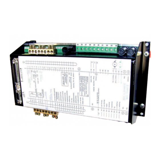
- Page 1 Manual Burner Control FA1 Sensors and Systems for Combustion Engineering www.lamtec.de...
- Page 3 Connecting the Burner Control FA1 ........
- Page 4 Table of Contents 6.16.8 Saving Changes ..........26 6.17 Fault .
- Page 5 11.16.1 Replacing a Burner Control FA1 ........
- Page 6 General Information General Information Validity of these Instructions These instructions apply to the FA1 and in any configuration. These devices conform to the following standards and regulations: • DIN EN 298: 2012-11 • DIN EN 1643: 2014-09 • DIN EN 13611:2011-12 •...
- Page 7 Safety Safety For Your Safety The following symbols are used in this document to draw the user's attention to important safe- ty information. They are located at points where the information is required. It is essential that the safety information is observed and followed, and that applies particularly to the warnings. DANGER! This draws the user's attention to imminent danger.
- Page 8 Brief Description Brief Description The Burner Control FA1 is suitable for control of burners and combustion systems for gase- ous, liquid and solid fuels, with permanent operation, also in hot air generators. Connections for Interbus-S, PROFIBUS DP, CANopen, TCP/IP (Modbus TCP) and Modbus RTU are available as optional equipment.
- Page 9 Display and Operational Controls Display and Operational Controls Intent of the keys: Reset Burner firing rate/fault history up Burner firing rate/fault history down MANUAL mode ON/OFF Fig. 4-1 Customer interface Changing display Display: Status burner firing rate –...
- Page 10 With the operating unit you may operate and the program the burner control system. Connecting the Burner Control FA1 1. Connect the operating unit to the FA1 by using a 9-pin Cannon connector. To do so, use the supplied connecting cable, type 663R0430.
- Page 11 The FA1 then interrogates the air pressure monitor. If this signal is in proper condtioion, the parameter set aeration time runs. When this time has expired the channel runs to the pro- grammed ignition position.
- Page 12 Commissioning Commissioning Basic Settings First configure the device (FA1) for the requirements of the system. Therefore set the following parameters. Recommendation: Use the LAMTEC PC software for Windows (available separately). The factory standard settings are indicated by an asteriks *.
- Page 13 Commissioning Select Language Select parameter 833 Value Language Value Language Value Language German* Portuguese Slovene English Polish Czech French Turk Coal-Oil-French Italian Croatian Coal-Gas-French Swedish Coal-Oil-German Hungarian Spanish Coal-Oil-English Romanian Dutch Coal-Gas-German Norse Slovak Coal-Gas-English Russian Danish...
- Page 14 Select parameter no. 774 and 775 (oil operation, gas operation). Short Text Description Default /FA1 ZüBr. ÖL Start with (1) or without (0) pilot burner for oil, (2)=oil with continuous ignition flame 0 = start without pilot burner - oil operation...
- Page 15 Commissioning Short Text Description Default /FA1 ZüBr.Gas Start with (1) or without (0) pilot burner for gas, (2)=gas with continuous ignition flame 0 = start without pilot burner - gas operation 1 = start with pilot burner - gas operation 2 = pilot burner also active in burner operation with continuous monitoring of the ignition flame.
- Page 16 If an output channel is set to flue gas re-circulation, attention must still be given to P 427. Short Text Description Default /FA1 ZEIT VO Pre-purge time in seconds Set the duration of pre-purge in this parameter. The commissioning engineer sets this value.
- Page 17 Select parameter no. 718. If the firing rate default is not provided by TPS signal, the parameter must be set to „0“ Short Text Description Default /FA1 Laufz L Running time in digit/min.. for TPS firing rate input (in 1200 0/500...
- Page 18 Commissioning Post-purge Time Select parameter 758 Short Text Description Default /FA1 ZEIT NA Post-purge time 1000 Post-purge time (in seconds) 0 = no post-purge 1000 = continuous purge (from 5.0 on) Set the pre-purge duration after a switch OFF. The air flaps were opened for this purpose.
- Page 19 These parameters have to be equal to the settings of the remote control software. Otherwise no communication is possible. Short Text Description Default /FA1 Baud S1 Baud rate of serial interface 1 This parameter defines the baud rate for the serial inter- face. The standard value is parameter content 4 (19,200 baud).
- Page 20 6.13 Set Pilot Burner (Maintenance Mode) Select parameter no. 787 Short Text Description Default /FA1 Wartung Maintenance mode (control unit only until stabilization time) 0 = maintenance mode OFF (main valves are opened) 1 = maintenance mode active 2 = curve set switch allowed in set mode Set the maintenance mode with this parameter.
- Page 21 Respect the directives for combustion plants, if you set this parameter. Short Text Description Default /FA1 AutStart Automatic restart after fault Automatic restart of the burner on fault condition. In the case of a fault for which the standards permit an auto- matic restart, this parameter initiates the restart.
- Page 22 Select parameter 796 and 798 (setpoint value 1 and setpoint value 2). With control by atmospheric condition select additionally parameter 797 and 799. Short Text Description Default /FA1 Soll1min Controller setpoint 1 minimum Firing rate controller setpoint 1 minimum (setpoint 1) in ° C or bar (xx.x) Set the minimum value for the first controller setpoint (active if input "set point switching"...
- Page 23 Control Range Select parameter no. 802 and 803 Short Text Description Default /FA1 EinschPt Burner start point Enter the switching point of the firing rate controller as the difference to the set point. [Switching point] = [setpoint] - [parameter content] e.
- Page 24 1 = display in °C (0... 320 °C) 2 = display in bar (P 810 and P 811) Select also for FA1, from which input the actual value signal should be taken. If the parameter is set to 1, the integrated PT100 input is used, other-...
- Page 25 Setting the Limit Switches of the Motors As soon as the FA1 is supplied with voltage, it attempts to drive the actuator motors to the low- er limit of the factory set curve. If the end-bearing's limit switches are not properly adjusted for...
- Page 26 NOTICE If the FA1 has 2 oil curves or 2 gas curves (parameter 776 at = 1 (oil) or = 2 (gas), curve set 1 (0 V) or curve set 3 (+24 V) can be chosen for oil and curve set 2 or curve set 4 can be cho- sen for gas.
- Page 27 Commissioning 6.16.4 Programming the Base Firing Rate Press keys 16 and 17 to set to ’firing rate value’. Press keys 2 and 3 to set to a value of ’200’. Press keys 16 and 17 to set to ’s. p. feedb.’. Press keys 2 and 9 to run the actuators to base fire position.
- Page 28 Press keys 3 and 2 to browse through the fault history. NOTICE If it is certain that the FA1 is fed with voltage at all the time since the last fault occured, it is possible to determine at what time the fault occurred from the present running time counter...
- Page 29 System Operation System Operation Release Settings by Customer Interface Beside terminal 59 FA1 can access the SETTING mode by using the customer interface alter- natively. Pre-requisite: The password for release level 1 must be set by the PC Remote Software.
- Page 30 NOTICE The total counter refers to the FA1's running time. It starts timing as soon as the unit is con- nected to a voltage source (this also provides the basis for the fault history). The individual running time counters refer to the burner's running time. They start timing as soon as the burner is in operation with the relevant curve set (flame signal is present).
- Page 31 System Operation Re-enter Range Limits NOTICE At least one actuator must be active. When changing the limit switch after programming, the range limits must be re-determined. Enter password (see chapter 6.2 Password Entry). Press key F3 → until the display shows ’SL’ in it’s centre. Press key11 ENTER the display shows ’cleared’.
- Page 32 Moving Screen "Actual Temperature is too high" Press key F3 MANUAL to start the FA1, even if the display shows the running text, subject to the condition, that the maximum temperature is not exceeded.
- Page 33 Internal Burner Firing Rate Controller Changing Setpoint of Burner-Firing-Rate Controller With an activated constant control: Set the firing rate with keys 16 and 17. On the left side of the display, the actual set- point 1 or setpoint 2 will be showed depending on the value terminal 50 has (0 V at terminal 50 = setpoint 1, 24 V on terminal 50 = setpoint 2).
- Page 34 Internal Burner Firing Rate Controller Steam Pressure If you get a steam-pressure signal from a pressure transmitter on terminal 3, 4 and 5, you must short-circuit the PT100 input at terminal 20 and 21. 8.10 Control by Atmospheric Condition If the burner firing rate controller is configured as "controlled by atmospheric conditions" the setpoint value can be shifted between the parameterised setpoint minimum and setpoint max- imum by connecting another PT 100 temperature sensor.
- Page 35 Internal Burner Firing Rate Controller Short Text Description Default /FA1 Soll1min Controller setpoint 1 minimum Firing rate controller setpoint 1 minimum (setpoint 1) in ° C or bar (xx.x) Set the minimum value for the first controller setpoint (active if input "set point switching" = 0) (weather guided controller) in this parameter.
- Page 36 *(1) = P 792 *(2) = P 793 Fig. 8-2 Startup sequence Short Text Description Default /FA1 Anf.Temp Max. start-up temperature Maximum start-up temperature or pressure in relation to the actual value Start - up circuit parameter: Enter the actual temperature, up to which the start - up circuit is active.
- Page 37 This is done by internal processing. If the actual value drops below the lower control range, a re-start can occur. Short Text Description Default /FA1 EinschPt Burner start point Enter the switching point of the firing rate controller as the difference to the set point.
- Page 38 Press key MANUAL again to cancel firing rate controller. It is also possible to switch the FA1 to "Manual Control" with the terminals. By short-circuiting the Pt100 signal (e.g. bridge terminal 19 and 20) the burner firing rate controller is switched off.
- Page 39 Internal Burner Firing Rate Controller 8.17 Checking the Safety Limiter For testing purposes of the safety limiter change the setpoint. This also causes a change in shut-off range as well. The safety limiter can therefore be overrun in manual mode. 8.18 Control Mode The firing rate controller tries to bring the actual value into line with the setpoint value.
- Page 40 Internal Burner Firing Rate Controller 8.19 Aides for Setting Characteristic Control Process Control Mode Start-up Procedure P term higher decrease of stronger reaction with faster start-up with attenuation overshoot overshoot P term smaller increase of less reaction, less ten- slower startup attenuation dency to oscillate Fig.
- Page 41 > min = 0. The FA1 checks this and if true then Main gas valve 1 is opened for a short time to allow gas to flow into the test line.
- Page 42 Valve Leakage Test Valve Leakage Test Flow Chart Fig. 9-1 Valve leakage test flow chart...
- Page 43 Therefore the minimal gas pressure of the burner must be set. The valve leakage test time t3 (P 311) would be set by FA1. The time t2 for FA1 is fixed to 2s. The time t3 (P 311) must be set in a way that the maximum allowable leakage rate Q Leck be securely detected.
- Page 44 Valve Leakage Test V V p = absolute pressure V = gas volume This is valid for the test of valve 1 V1: Should t3 be negative, at least 1s must be set. If the calculation of t3 for valve 2 is higher than t3 for valve 1, the value for the calculation of valve 2 must be adjusted.
- Page 45 Standby 10.1 Standby mode In this mode the FA1 enables a switchback to pilot burner mode. The burner re-starts without pre-purge in the 2 safety time. You can activate STANDBY mode, if the internal firing rate controller is active or if an external input or output command can be connected to LSB module or fieldbus (see parameter 812, access level 4).
- Page 46 Otherwise use one flame detector for the main flame and one for the pilot flame. If the "Burner ON" signal will be removed during stand-by mode, the FA1 switches OFF. This shut-off proceeds like a shut-off out of the modes BASE FIRING RATE/CONTROL with all it’s parameter set procedures.
- Page 47 Standby 10.3 Switching into Standby Mode via LSB module Fig. 10-3 Switching in STANDBY mode via LSB module...
- Page 48 → IGNITION POSITION or IGNITION → SETTING/IGNITION position (same as IGNITION, but FA1 on SET- TING) → BASE FIRING RATE → SETTING/BASE FIRING RATE” (as BASIC FIRING RATE, but FA1 on SETTING) → POST-PURGE → BURNER OFF (no signal present) →...
- Page 49 NOTICE We recommend the LAMTEC flame monitoring systems (like F300K, F200K2), if you have other requirements for the flame monitoring (e.g. combustion of coal dust). You will find infor- mation on this devices in the corresponding manuals (DLT7650, DLT7600 and DLT7502/ DLT7503).
- Page 50 Appendix WARNING! Do not open FFS08 UV and FFS 06 UV! Setting of the sensitivity is not possible for FFS08 UV and FFS06 UV. FFS07 FFS05 (up to January 2014, replaced by FFS07) Fig. 11-3 FFS07, FFS 05 Adjusting the flame sensitivity - factory settings IR 50%/UV 100% FFS08 IR FFS06 (up to January 2014,...
- Page 51 WARNING! If the FA1 is used with an integral flame monitor, terminal 53 may not be connected to any oth- er components The optical flame sensors are supplied together with a connecting cable of ca. 2 m length. The line between the sensor and the flame monitoring unit may be extended up to a distance of 500 m.
- Page 52 4.0 the automatic flame guard plug- in card has to be removed from the FA1, from base version 5.0 on the bridge 450 (beside the 96-pole plug) has to be switched.
- Page 53 Appendix – In rarely cases the shielding may be disconnected like described in section a) and the sensor housing may be grounded at the burner plate. Adverse effects through coupling into the laid cable may be eliminated normally only with the correct laying and in some cases with an adequate grounding point.
- Page 54 Appendix 11.4 Fault Codes Technical Regulations for Steam Boilers (P425 = 1, P836 = 1) EN676 European standard 676 ’Automatic Forced Draught Burners for Gaseous Fuels " (P425 = 1, P836 >1) Fault Restart according to Description Code EN676 No fault code available for this fault Ignition flame does not appear.
- Page 55 Appendix Fault Restart according to Description Code EN676 The flame signal extinguishes during the second safety time H/Ü Check flame stability. Check wiring. Check flame sensor. Flame signal does not appear during safety time H/Ü Check flame stability. Check wiring. Check flame sensor.
- Page 56 For more details, see the "Protected data record" description in the remote control software. If this is not possible, you must order a preprogrammed EEPROM from LAMTEC. When ordering, you must enter the device number and software checksums. Only in this way are mix-ups excluded. For the address, see the overleaf of this publica-...
- Page 57 If fault messages are constantly appearing one after the other the EPROM pro- gramme is possibly defective. Request a new programme EPROM from LAMTEC with the precise specification of the respective purchase order number, sales order number, and commission of the device.
- Page 58 Appendix Fault Restart according to Description Code EN676 RAM-Test detected error H/Ü Fault during an internal self-test. Reset the fault; switch the mains voltage off and on again if necessary. Check all fuses in the device. Check the curve points of the main and monitoring processors for irregularities. ...
- Page 59 For more details, see the "Protected data record" description in the remote control software. If this is not possible, you must order a preprogrammed EEPROM from LAMTEC. When ordering, you must enter the device number and software checksums. Only in this way are mix-ups excluded. For the address, see the overleaf of this publica- tion.
- Page 60 Appendix Fault Restart according to Description Code EN676 Potentiometer faulty, feedback changing too quickly: channel 2 H/Ü See S141 Potentiometer faulty, feedback changing too quickly: channel 3 H/Ü See S141 Potentiometer faulty, feedback changing too quickly: channel 4 H/Ü See S141 Potentiometer faulty, feedback changing too quickly: channel 5 H/Ü...
- Page 61 Appendix Fault Restart according to Description Code EN676 >88 Monitoring direction of ratation: channel 3 H/Ü The channel is not running or does not start on time. During operation, the channel briefly changes direction. Check the servo motor. >88 Monitoring direction of ratation: channel 5 H/Ü...
- Page 62 Appendix Fault Restart according to Description Code EN676 >88 Fuel/air ratio control blocked: channel 1 >88 Fuel/air ratio control blocked: channel 2 >88 Fuel/air ratio control blocked: channel 3 >88 Fuel/air ratio control blocked: channel 4 >88 Fuel/air ratio control blocked: channel 5 Broken wire at firing rate input -1 H/Ü...
- Page 63 Appendix Fault Restart according to Description Code EN676 Internal communication between the processors faulty H/Ü Different values in the main and monitoring processors. Reimport the curves and/or parameter set. A sporadic occurrence of fault H370 is due to EMC interference immunity of the wir- ing or environment.
- Page 64 Appendix Fault Restart according to Description Code EN676 Ignition position was left in ignition mode. Channel: 3 H/Ü In case of a constant output: Possible EMC influences due to ignition transformer; check the frequency converter settings Ignition position was left in ignition mode. Channel: 4 H/Ü...
- Page 65 Appendix Fault Restart according to Description Code EN676 Internal comparison: relay output terminal 16 or 65 (ETAMATIC) not dropping out. See S500 Internal comparison: relay output terminal 11 or 66 (ETAMATIC) not dropping out. See S500 Internal comparison: relay output terminal 45 not dropping out. See S500 Internal comparison: relay output terminal 68 or 61 (ETAMATIC) not dropping out.
- Page 66 Appendix Fault Restart according to Description Code EN676 Oil fuel blocked because a required solenoid valve is not connected The test current for the TRIAC self-test cannot flow. Gas fuel blocked because a required solenoid valve is not connected The test current for the TRIAC self-test cannot flow. No valve connected? Check fuse F3 and F4 The oil and gas valves are not connected.
- Page 67 Appendix Fault Restart according to Description Code EN676 Flame signal goes out even though signal on terminal 2 still present. VMS, for ETA V Term. 58 Illegal operating mode change Ü Check the "Burner ON" signal. Bouncing signal? Incorrect signal combination in operating mode AU Incorrect signal combination in operating mode BE Incorrect signal combination in operating mode VO Incorrect signal combination in operating mode ZP...
- Page 68 Time interval between remote-fault-resets is too short. EN 14459 permits a remote unlocking only 4 x within 15 minutes. The fault release is monitored by the remote control software, LAMTEC system bus, and field bus (parameter 19). When exceeded, fault deactivation H889 is gen- erated and additional remote fault releases are ignored.
- Page 69 Check all fuses in the device. If fault messages are constantly appearing one after the other exchange the device or respective card. Curve set adjustment via LAMTEC SYSTEM BUS, selftest recognizes fault Error in reference, channel: 1 Ü Fault during an internal self-test.
- Page 70 Appendix Fault Restart according to Description Code EN676 Error in reference, channel: 2 Ü See S911 Error in reference, channel: 3 Ü See S911 Error in reference, channel: 4 Ü See S911 Fault in reference, duct: 5 Ü See S911 Relay driver self-test : output terminal 11 or 66 (ETAMATIC) faulty.
- Page 71 Appendix Fault Restart according to Description Code EN676 Relay driver self-test : Output K203 defect. H/Ü See S921 Relay driver self-test : Output K201 defect. H/Ü See S921 >88 Default language missing or LANGUAGE-FLASH defect Fault during an internal self-test. Reset the fault;...
- Page 72 Appendix 11.5 Calling Up the Condition of the Digital Inputs Mit den Tasten 16 und 17 auf DIGITALE EINGÄNGE schalten. Bedeutung der digitalen Eingänge FA1 Signal liegt an Signal liegt nicht an...
- Page 73 11.6.1 Set Pilot Burner Setting the "Service mode" parameter (P 787) causes the FA1 operating program to run only up to the stabilisation time. But up to 5 successive starts can be attempted without pre-purge and without valve leakage test. After setting the pilot burner, set parameter back to 0 NOTICE Resetting a fault with a total reset clears the internal counter for the service mode.
- Page 74 Appendix 11.7 Process Sequence Charts Fig. 11-5 Process sequence chart gas operation with pilot burner and actuator...
- Page 75 Appendix Fig. 11-6 Process sequence chart gas without pilot burner, with actuator...
- Page 76 Appendix Fig. 11-7 Process sequence chart oil with pilot burner and actuator...
- Page 77 Appendix Fig. 11-8 Process sequence chart oil without pilot burner, with actuator...
- Page 78 Appendix Key to process sequence charts Any condition Wait for gas safety interlock circuit air pressure monitor min. scan Time for pressure build-up in the gas test line (only with valve leakage test activated) 2 sec. Servo drive running time 30-60 sec.
- Page 79 Etam.OEM ETAMATIC OEM (0=ETAMATIC, 1=ETAMATIC OEM, 2=BurnerControl, 3=Special 0 = ETAMATIC 1 = ETAMATIC OEM 2 = BurnerControl FA1 3 = BurnerControl FA1 without continuous output (from Software version v5.5 on) Terminal connections: ETAMATIC ETAMATIC OEM Burner Control FA1 Burner Control FA1...
- Page 80 (P 18 = 1) WARNING! P 762 = 0 terminal 46 has no function (ETAMATIC OEM and Burner Control FA1)! P 17 = 3 (FA1 special) terminal 46 is set to ’ignition position acknowledgement’! ’Oil pressure > min’ or ’atomiser air pressure’ is not monitored by terminal 46!
- Page 81 ETAMATIC OEM terminal 54 0 = gas pressure < max. 1 = ignition flame signal Burner Control FA1 0 = gas pressure < max. 1 = ignition flame monitor at input ignition flame signal (see P 728, P 774 and...
- Page 82 Appendix 11.8 Connection Diagrams Fig. 11-9 Connecting diagram of FA1 with pilot flame monitoring and control output for mechanical fuel/ air ratio control or 4 ... 20 mA inverter alternatively (for footnotes refer to the process sequence charts).
- Page 83 Appendix Fig. 11-10 Connecting diagram FA1 with pilot flame monitoring, without continuous control output (for footnotes refer to the process sequence charts)
- Page 84 Appendix 11.9 Connection Examples of Firing Rate Input A three-point step signal from the firing rate controller is used as the firing rate input. Use the contacts instead of the potentiometer as shown below: Current is used as firing rate default signal instead of a potentiometer: f.ex.
- Page 85 Appendix 11.10 Flame Scanner and Sensor Connection 11.10.1 Flame Scanner Connection Fig. 11-11 Connection flame scanner Flame intensity to align the flame sensor (not connected during operation), with delivery of 01.01.2003 on. Colour coding according to IEC 60757 for Fig. 11-11 Connection flame scanner Black White Pink...
- Page 86 Appendix 11.10.2 Flame Sensor Connection 11.10.2.1FFS07 Assembly BK Schwarz RD Rot Weiß BU Blau GN Grün Gelb PK Rosa Empfohlener Einbauort 4 Dichtring muss einrasten!
- Page 87 Appendix 11.10.2.2FFS08 Assembly BK Black RD Red White BU Blue GN Green Yellow PK Pink Recommended installa- Seal ring must engage! tion...
- Page 88 The document "LAMTEC SYSTEM BUS technical documentation“ (publication no. DLT6095) consists of further information with regards to LAMTEC SYSTEM BUS. 11.11.1 LSB Connection Fig. 11-12 LSB connection FA1 to LT2 Fig. 11-13 LSB connection FA1 - LT2 - other LAMTEC devices Description To other LAMTEC-devices Housing...
- Page 89 Appendix Fig. 11-14 LSB connection FA1 o LT1 from SN 600 on Description PE-bar in housing LT1 Housing Pre-canned line 2m, 663R0421N LT1 from serial number 0600 Terminal resistance active To other LAMTEC- devices Fig. 11-15 LSB-Connection FA1 - LT 1 to SN 0599...
- Page 90 LAMTEC SYSTEM BUS, connection cable 663R0421N 11.11.2 LSB Cable Connection Devices on LAMTEC SYSTEM BUS (LSB) must be connected in serial/row (see Fig. 11-17 Serial BUS connection). The first and the last participant on LSB must be terminated with a termination resistor of 120 .
- Page 91 Fig. 11-19 Internal connecting diagram of the control outputs Always connect the attached firing rates (valves etc.) to the FA1 (even when the burner is off). If it is not possible to not ensure this, use an RC combination (ca. 0,15 μF, ca. 220 ) between the output terminal and neutral to let the testing current flow.
- Page 92 Enable terminal no. 67 for 2 sec. to release the gas. Ensure that this time is long enough, even for mostly used gaspipes with a smaller diameter to release the gas. Fig. 11-21 Suggested wiring for venting the gas line over the roof in conjunction with the FA1...
- Page 93 Appendix 11.14 Switch- and Key Combinations 11.14.1 Programming Unit Action Display Mode Keys recall correction range status monitoring display automatic press key 11 (Enter) setting reset press key F1 (Reset) code entry for parameter set- status automatic tings press keys 5, 7 and 8 simultaneously scan fault history status monitoring display...
- Page 94 Appendix Action Display Mode Keys mode switching O -con- automatic trol FA1 press key F4 (M) twice fault reset status control Mode O control, press key 11 (Enter), recall fault history press key 7 call up text messages status control...
- Page 95 Feedback at Three-Point-Step Outputs 11.15.1 Connect with Positive Locking Since the FA1, in the case of three-point step channels, adjusts the damper until the actual value is equal to the setpoint value, the feedback potentiometer must always reliably corre- spond to the damper position.
- Page 96 Rating Contelec PL 295 Rating: 5 kΩ* Bourns 6639S-095-.. Rating: 5 kΩ* Other potentiometers are permitted only after consulting LAMTEC or the TÜV. Examples of servomotors Servomotors with approved potentiometer, fitted with a positive interlock connection: Manufacturer Description Potentiometer LAMTEC 662R2111...
- Page 97 To verify the actual data, download them from the device and compare them with the protect- ed dataset. Finally download the actual dataset from the device and send it to support@lamtec.de. 11.16.2 How to Replace a Servo Motor If you replace a motor without pre-calibration it is necessary to check the burner adjustment after the change, because the potentiometer value and the position of the switches may differ a little bit.
- Page 98 Extraction tool for EPROMS 1. Removing a) Switch off power supply b) Disconnect plugs c) Take out FA1 ggf. from the control cabinet 2. Open the housing a) 1 – open screw M2,5 2 – open hex-hat nuts M3 (4 pcs.).
- Page 99 Appendix b) 1 – Remove cover 2 – Disconnect PE connection Fig. 11-24 Housing is open 3. Remove base electronic board. The base electronic board (3) and the rear wall are mounted to one unit (4) and can be dismounted from the CPU board (1) easily. EPROMs/EEPROM/memory extension are built in the CPU board (1).
- Page 100 Appendix NOTICE Important: Always pay attention to the direction of the notches before replacing them. The notches point towards the PE connector. Fig. 11-26 Tongs to remove EPROM, EE- PROM and memory extension Fig. 11-27 Lever out EPROM - if tongs are not available a) Lever out the old EPROMs very carefully out of their sockets.
- Page 101 The new EEPROS are changeing the CRC 4 check sums e) Correct the software version on the configuration lable. . Send the new CRC check sum and the new software version to LAMTEC for complet- en the CV of the device.
- Page 102 Appendix 11.18 Wiring Notes 11.18.1 Shields Connection All cables from and to the FA1 must be shielded (with the exception of the 230 V cable). Con- nect the shielding to PE by the shortest possible route. Right: shielding terminal connection terminal...
- Page 103 14 digital inputs 24V 3 analogue inputs Digital signal inputs The Burner Control Fa1 self tests will not allow the parasitic capacitance on the line connected to the digital inputs to exceed 2,2F. The length of the cables should not exceed 10 m (32.8 ft.)
- Page 104 – 1 serial 25-pole Sub-D socked (only addressable with adapter RS 232 (standard setting 19200 baud, no parity, 8 data bits, 1 stop bit) – LAMTEC SYSTEM BUS (length max. 500 m (0.3 mile)) Bus coupling LSB- Adapter BUS card optional for these systems...
- Page 105 LAMTEC SYSTEM BUS Communications interface Fig. 11-30 Rear view FA1 NOTICE PC connection possible only via LAMTEC interface adapter! NOTICE For exchange of the fuses F3, F4, F5 these specifications are to be complied: - 2A slow blow - high breaking capacity according to IEC 60127-2, Sheet 5: 1500A @ 250VAC - melting integral I²t <...
- Page 106 Appendix 11.19.2 Customer Interface Fig. 11-31 Customer interface Fig. 11-32 Dimensions of the customer interface...
- Page 107 Appendix Fig. 11-33 Cut-out for panel board Dimensions Dimension (HxWxD) 72 mm x144 mm x56 mm Weight 1,0 kg Input data Spannungsversorgung 24 VDC Leistungsaufnahme 60 mA Features Display Alphanumeric display, 2 x16 digits, switchable to firing rate value, state, O value, flame intenstiy, running text Environmental conditions Ambient temperature...
- Page 108 Appendix 11.19.3 Programming Unit Length: 180 mm Width: 94 mm Depth: 40 mm Fig. 11-34 Programming Unit Fig. 11-35 Dimensions Programming Unit Dimension Dimension (HxWxD) 180x94x40 mm/7.1x3.7x1.6 in Weight 0,33 kg/0.7lb Input data Power supply 24 VDC Power consumption 100 mA Features Programming unit 4x16 characters can display with softkeys and setup-assistant...
- Page 109 Appendix 11.20 Burner Control FA1 without integral flame detector Connectable flame detectors: Any tested flame sensor with error-proof floating contact for flame signalling WARNING! If a flame monitor, which is not approved for continuous operation is connected, the entire sys- tem's approval for continuous operation will loose it’s validation.
- Page 110 Appendix Marking Colour black blue green white yellow Fig. 11-39 Flame sensor FFS 07 Description Type plate Grounding M4 (Pozidrive 2) Incidence of light Bend radius of the of the FM wire min. 25 mm...
- Page 111 Appendix 11.22 Declaration of Conformity...
- Page 112 Appendix...
- Page 113 Appendix...
- Page 114 The information in this publication is subject to technical changes. LAMTEC Meß- und Regeltechnik für Feuerungen GmbH & Co. KG Wiesenstraße 6 D-69190 Walldorf Telefon: +49 (0) 6227 6052-0 info@lamtec.de Telefax: +49 (0) 6227 6052-57 www.lamtec.de Printed in Germany | Copyright 2018...
Need help?
Do you have a question about the FA1 and is the answer not in the manual?
Questions and answers