
Related Manuals for Lamtec FA1


Summary of Contents for Lamtec FA1
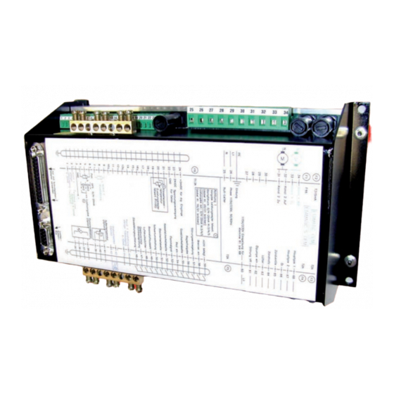
- Page 1 Quick Reference for Endusers Burner Control FA1 Sensors and Systems for Combustion Engineering www.lamtec.de...
-
Page 3: Table Of Contents
Connecting the Burner Control FA1 ........ -
Page 4: General Information
General Information General Information Validity of these Instructions These instructions apply to the following device(s): FA1 in any configuration. These devices conform to the following standards and regulations: • DIN EN 298: 2012-11 • DIN EN 1643: 2014-09 • DIN EN 13611:2011-12 •... -
Page 5: Safety
Safety Safety For Your Safety The following symbols are used in this document to draw the user's attention to important safe- ty information. They are located at points where the information is required. It is essential that the safety information is observed and followed, and that applies particularly to the warnings. DANGER! This draws the user's attention to imminent danger. -
Page 6: Brief Description
Brief Description Brief Description The Burner Control FA1 is suitable for control of burners and combustion systems for gase- ous, liquid and solid fuels, with permanent operation, also in hot air generators. Connections for Interbus-S, PROFIBUS DP, CANopen, TCP/IP (Modbus TCP) and Modbus RTU are available as optional equipment. -
Page 7: Life Cycle
Brief Description Life Cycle FA1 Burner Control has a designed lifetime of 250,000 burner start-up cycles, which, under normal operating conditions in heating mode, correspond to approx. 10 years of usage (starting from the production date given on the type plate). -
Page 8: Customer Interface
Customer Interface Customer Interface Description of key functions: → RESET → Firing-rate/fault history up → Firing-rate/fault history down → MANUAL mode EIN/AUS Fig. 4-1 Customer interface → Umschaltung der Anzeige – Fuel/air ratio control – – Flame intensity – Operating hours Display and Operational Controls Fig. -
Page 9: Key Functions
In the initial state of the display (not on manual mode) while no fault of FA1 is pending, the upper indicator line switches to: •... -
Page 10: Display Level 2
Manual Function of the manual key In the HAND mode, the regular firing rate input of FA1 can be manually adjusted. Press HAND key → LED in HAND key lights up With these arrow keys the firing rate value can be adjusted. -
Page 11: Operating Unit
With the operating unit you may operate and the program the burner control system. Connecting the Burner Control FA1 1. Connect the operating unit to the FA1 by using a 9-pin Cannon connector. To do so, use the supplied connecting cable, type 663R0430. -
Page 12: Fault
The FA1 records the last 10 faults including the corresponding operating hours counter value. In initial state (not MANUAL mode), provided that no fault message of the FA1 is pending, the upper display line is switching over: You may scroll through the fault history using the arrow keys. -
Page 13: Internal Burner Firing Rate Controller
Press key MANUAL again to cancel firing rate controller. It is also possible to switch the FA1 to "Manual Control" with the terminals. By short-circuiting the Pt100 signal (e.g. bridge terminal 19 and 20) the burner firing rate controller is switched off. -
Page 14: Displaying The Running Time Meter
The counter refers to the total sum of operating hours of FA1. It is started as soon as voltage is applied to the device (this counter also provides basic data to fault history). -
Page 15: Calling The Checksums
One after the other is shown: CRC 16 of level 0, 1 and 2→ changeable by authorised personnel only CRC 16 der Ebene 4 → changeable by LAMTEC only 1. safety time oil in s 2. safety time oil in s 1. -
Page 16: Appendix
→ IGNITION POSITION or IGNITION → SETTING/IGNITION position (same as IGNITION, but FA1 on SET- TING) → BASE FIRING RATE → SETTING/BASE FIRING RATE” (as BASIC FIRING RATE, but FA1 on SETTING) → POST-PURGE → BURNER OFF (no signal present) →... -
Page 17: Fuses
LAMTEC SYSTEM BUS Communications interface Fig. 8-3 Rear view FA1 NOTICE PC connection possible only via LAMTEC interface adapter! NOTICE For exchange of the fuses F3, F4, F5 these specifications are to be complied: - 2A slow blow - high breaking capacity according to IEC 60127-2, Sheet 5: 1500A @ 250VAC - melting integral I²t <... -
Page 18: Eu Declaration Of Conformity
Appendix EU Declaration of Conformity... - Page 19 Appendix...
- Page 20 Appendix...
- Page 21 Appendix...
- Page 22 The information in this publication is subject to technical changes. LAMTEC Meß- und Regeltechnik für Feuerungen GmbH & Co. KG Wiesenstraße 6 D-69190 Walldorf Telefon: +49 (0) 6227 6052-0 info@lamtec.de Telefax: +49 (0) 6227 6052-57 www.lamtec.de Printed in Germany | Copyright 2020...
Need help?
Do you have a question about the FA1 and is the answer not in the manual?
Questions and answers