
Related Manuals for SPX FLOW Johnson Pump CombiProLine OH3


Summary of Contents for SPX FLOW Johnson Pump CombiProLine OH3
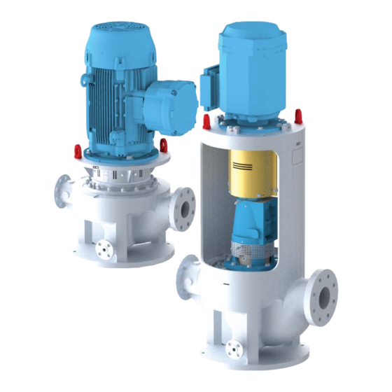
- Page 1 INSTRUCTION MANUAL CombiProLine Vertical heavy duty process in-line pump according to API 610 (OH3 & OH5) Orginal instructions CRL/EN (1810) 2.2 Read and understand this manual prior to operating or servicing this product...
- Page 3 EC Declaration of conformity (Directive 2006/42/EC, appendix II-A) Manufacturer SPX Flow Technology Assen B.V. Dr. A.F. Philipsweg 51 9403 AD Assen The Netherlands hereby declares that all pumps member of productfamilies CombiBloc, CombiBlocHorti, CombiChem, CombiDirt, CombiFlex(U)(B), CombiPrime H, CombiLine, CombiLineBloc,...
- Page 4 EC/EN (1712) 6.0...
- Page 5 SPXFLOW is a global multi-industry manufacturing leader. The company's highly- specialized, engineered products and innovative technologies are helping to meet rising global demand for electricity and processed foods and beverages, particularly in emerging markets. SPX Flow Technology Assen B.V. P.O. Box 9 9400 AA Assen The Netherlands Tel.
- Page 6 INT/EN (1512) 1.2...
-
Page 7: Table Of Contents
CombiProLine Table of Contents Introduction Preface Safety Guarantee Inspection of delivered items Instructions for transport and storage 1.5.1 Weight 1.5.2 Use of pallets 1.5.3 Hoisting 1.5.4 Storage Ordering parts General Pump description Applications Type code Serial number Construction Pump casing Impeller Pump cover Wear rings... - Page 8 Connection of the electric motor Commissioning Inspection of the pump Inspection of the motor Preparing the pump unit for commissioning Checking the sense of rotation Start-up Pump in operation Noise Maintenance Daily maintenance Mechanical seal Lubrication of the bearings 5.3.1 OH3 pump 5.3.2 OH5 pump...
- Page 9 CombiProLine 9.2.1 Sectional drawing pump 9.2.2 Parts list pump Bearing OH3 9.3.1 Sectional drawing bearing 9.3.2 Parts list bearing Pump OH5 9.4.1 Sectional drawing pump 9.4.2 Parts list pump Mechanical seal piping plan 11 - tubing 9.5.1 Drawing plan 11 - tubing 9.5.2 Parts list plan 11 - tubing Mechanical seal piping plan 11 - flanged...
- Page 10 CRL/EN (1810) 2.2...
-
Page 11: Introduction
CombiProLine 1 Introduction Preface This manual is intended for technicians and maintenance staff and for those who are in charge of ordering spare parts. This manual contains important and useful information for the proper operation and maintenance of this pump. It also contains important instructions to prevent potential accidents and damage, and to ensure safe and fault-free operation of this pump. -
Page 12: Guarantee
Guarantee SPXFLOW shall not be bound to any guarantee other than the guarantee accepted by SPXFLOW. In particular, SPXFLOW will not assume any liability for explicit and/or implicit guarantees such as but not limited to the marketability and/or suitability of the products supplied. -
Page 13: Hoisting
CombiProLine 1.5.3 Hoisting When hoisting a pump unit OH3 or pump unit OH5 the straps must be fixed in accordance with figure 1 and figure 2. When lifting a pump unit always use a proper and sound lifting device, approved to bear the total weight of the load! Never go underneath a load that is being lifted! If the electric motor is provided with a lifting eye, this lifting eye is intended only for the purpose of carrying out service activities to the electric motor! -
Page 14: Storage
Figure 2: Lifting instructions for OH5 pump unit. 1.5.4 Storage If the pump is not to be used immediately the pump shaft must be turned by hand twice per week. Ordering parts This manual contains a survey of the spare parts recommended by SPXFLOW as well as the instructions for ordering them. -
Page 15: General
CombiProLine 2 General Pump description The CombiProLine represents a range of vertical "heavy duty" centrifugal pumps. The design of this range of pumps is based on the guidelines for: "Centrifugal Pumps for Petroleum, Petrochemical and Natural Gas Industries" from the "American Petroleum Institute"... -
Page 16: Type Code
Type code Pumps are available in various designs. The main characteristics of the pump are shown in the type code. Example: CRL 50A-200 OH3 A-8 1CW-FX Pump family CombiProLine Pump designation vertical, in-line close-coupled, vertical, in-line Pump size discharge connection [mm]. A and B design pump types have the same designation though they have different hydraulic performances nominal impeller diameter [mm] Pump casing material according to API 610... -
Page 17: Serial Number
CombiProLine Serial number Serial number of the pump or pump unit are shown on the name plate off the pump and on the label on the cover of this manual. Example: 01-1000675A year of manufacture 100067 unique number number of pumps pump with motor pump with free shaft end Construction... -
Page 18: Impeller
Impeller The back of the closed impeller is provided with back vanes in order to limit the pressure on the shaft seal and to allow the flushing liquid to circulate. Contamination of the shaft seal is also prevented. On the inlet side the impeller is provided with an interchangeable wear ring. -
Page 19: Re-Use
CombiProLine 2.14 Re-use The pump may only be used for other applications after prior consultation with SPXFLOW or your supplier. Since the lastly pumped medium is not always known, the following instructions should be observed: 1 Flush the pump properly. 2 Make sure the flushing liquid is discharged safely (environment!) Take adequate precautions and use the appropriate personal protection means like rubber gloves and spectacles! - Page 20 General CRL/EN (1810) 2.2...
-
Page 21: Installation
CombiProLine 3 Installation Safety • Read this manual carefully prior to installation and commissioning. Non-observance of these instructions can result in serious damage to the pump and this will not be covered under the terms of our guarantee. Follow the instructions given step by step. •... -
Page 22: Mounting Oh3 Pump
Mounting OH3 pump 3.4.1 Installation of a pump unit Pump and motor shafts of complete pump units are adjusted perfectly in line in the works. 1 In case of permanent arrangement place the base plate level on the foundation with the aid of shims. -
Page 23: Tolerances For Aligning The Coupling
CombiProLine Parallel alignment 1 Mount dial gauge (A) on the coupling halve motor side, see figure 3. 2 Make index lines on the two coupling halves. 3 Set the dial gauge pointer to zero, turn motor shaft 360 °. 4 Read dial gauge (A). Add or remove shims under the motor until the reading of the dial gauge is within the allowable tolerance, see paragraph 3.4.4 "Tolerances for aligning the coupling". -
Page 24: Accessories
Figure 4: Eccentric reducer to suction flange. • The maximum allowable system pressure is stated in paragraph 2.13 "Application area". If there is a risk that this pressure might be exceeded, for instance because of an excessive inlet pressure, appropriate measures should be taken by mounting a safety valve in the piping. -
Page 25: Commissioning
CombiProLine 4 Commissioning Inspection of the pump Check whether the pump shaft turns freely. Do this by turning the shaft end at the coupling a few times by hand. Inspection of the motor Check whether the fuses have been mounted. Preparing the pump unit for commissioning Proceed as follows, both when the unit is put into operation for the first time and after the pump has been overhauled. -
Page 26: Pump In Operation
Pump in operation When the pump is in operation, pay attention to the following: • The pump should never run dry. • Never use a stop valve in the suction line to control pump output. The stop valve should always be fully opened during operation. •... -
Page 27: Maintenance
CombiProLine 5 Maintenance Daily maintenance Regularly check the outlet pressure. No water should get into the terminal box of the electric motor when the pump room is sprayed clean! Never spray water on hot pump parts! The sudden cooling down may cause them to burst and hot water may flow out! Flawed maintenance will result in shorter lifespan, possible break down and in any event loss of warranty. -
Page 28: Noise
Noise If a pump starts making noise, this may point to certain problems with the pump unit. A crackling noise can indicate cavitation or excessive motor noise can indicate deterioration of the bearings. Motor Check motor specifications for start-stop frequency. Faults The pump, of which you want to determine the fault, may be hot or under pressure. -
Page 29: Problem Solving
CombiProLine 6 Problem solving Faults in a pump installation can have various causes. The fault may not be in the pump, it may also be caused by the pipe system or the operating conditions. Firstly, always check that installation has been executed in accordance with the instructions in this manual and that the operating conditions still correspond with the specifications for which the pump was purchased. - Page 30 Table 4: Possible causes of pump failures. Possible causes Pump or suction pipe is not sufficiently filled or de-aerated Gas or air coming from the liquid Air lock in the suction pipe Air leak in the suction pipe The manometric suction head is too high Suction pipe or suction strainer is blocked Insufficient immersion of foot valve or suction pipe during operation of the pump NPSH available too low...
-
Page 31: Disassembly And Assembly
CombiProLine 7 Disassembly and assembly Precautionary measures Take adequate measures to avoid that the motor is started while you are working on the pump. This is especially important for electric motors with remote control: • Switch the operating switch near the pump (if available) to "OFF". •... -
Page 32: Disassembly And Assembly Top Pull Out Unit Oh3
Disassembly and assembly Top Pull Out unit OH3 ➢ The Top Pull Out unit and the electric motor of large pumps are too heavy to be lifted by hand. Use appropriate hoisting equipment. The pumps are designed with a Top Pull Out system. For that reason they are provided with a "spacer"-coupling. -
Page 33: Disassembly And Assembly Top Pull Out Unit Oh5
CombiProLine Disassembly and assembly Top Pull Out unit OH5 ➢ The Top Pull Out unit and the electric motor of large pumps are too heavy to be lifted by hand. Use appropriate hoisting equipment. The pumps are designed with a Top Pull Out system. The electric motor with the lantern piece, the pump cover and the impeller can be dismantled as a whole. -
Page 34: Replacing The Impeller And The Wear Ring
Replacing the impeller and the wear ring If the play has risen to 0,9 mm or greater due to wear then both wear rings are replaced. 7.7.1 Disassembling the impeller 1 Remove the Top Pull Out unit, see paragraph 7.5.1 "Disassembling the Top Pull Out unit OH3"... -
Page 35: Assembling The Wear Rings
CombiProLine 2 Unlock the set screw (0155) that lock up the impeller wear ring (0150) on the impeller. 3 Unlock the set screw (0135) that lock up the casing wear ring (0130) on the impeller. 4 Measure the thickness (d) and the width (b) of the ring, see figure 5 A. 5 Make a centre hole in the middle of the edge of the ring at two opposite points, see figure 5 B. -
Page 36: Mechanical Seal
Mechanical seal 7.8.1 Instructions for mounting a cartridge seal ➢ First read the following instructions regarding mounting a cartridge seal. Follow these instructions closely when mounting a cartridge seal. • This mechanical seal comes as a ’full cartridge seal’. This means that this mechanical seal must be mounted as one single piece and that it shall NOT be taken apart! •... -
Page 37: Bearing Oh3
CombiProLine Bearing OH3 7.9.1 Instructions for assembly and disassembly of bearings ➢ First read the following instructions regarding assembly and disassembly. Follow these instructions closely when assembling and disassembling bearings. Disassembly: • Use a proper puller to remove the bearings from the pump shaft. •... -
Page 38: Assembling Bearing
7.9.3 Assembling bearing 1 Clean the interior of the bearing bracket properly. 1 Subsequently fit the Nilos ring (2310), the inner circlip (2300), the Nilos ring (2320) and the adjusting ring (2375) on the pump shaft. Make sure the Nilos rings are positioned properly! 2 Preheat the angular contact ball bearings and the inner ring of the cylindrical roller bearing and fit them onto the pump shaft. -
Page 39: Dimensions
CombiProLine 8 Dimensions For dimension see GAD enclosed with the delivery. Dimensions CRL/EN (1810) 2.2... - Page 40 Dimensions CRL/EN (1810) 2.2...
-
Page 41: Parts
CombiProLine 9 Parts Ordering parts 9.1.1 Order form You can use the order form included in this manual for ordering parts. When ordering parts always quote the following data: 1 Your address. 2 The quantity, the item number and the description of the part. 3 The pump number. -
Page 42: Pump Oh3
Pump OH3 9.2.1 Sectional drawing pump 2420 1930 1905 1900 0950 0960 0960 1950 0955 1920 2430 0895 0210 0290 0896 0890 2410/2415 2460/2465 2470/2475 0270 0920/0925/0930 0250 0940 1800 0910 1810 0930 1815 0925 1220 0920 0800 0275 0810 0820 0805 0850... -
Page 43: Parts List Pump
CombiProLine 9.2.2 Parts list pump API-610 Material Classes Item Quantity Description chrome stainless super 0100 pump casing carbon steel duplex steel steel duplex chrome stainless super 0110 pump cover carbon steel duplex steel steel duplex chrome stainless chrome stainless super impeller cast iron duplex... - Page 44 API-610 Material Classes Item Quantity Description 1810 stainless steel 1815 washer stainless steel stainless chrome stainless super cap nut 4140 steel duplex 1820 steel steel steel duplex super set screw stainless steel 1825 duplex duplex 1900 stud bolt carbon steel 1905 washer steel...
-
Page 45: Bearing Oh3
CombiProLine Bearing OH3 9.3.1 Sectional drawing bearing 2200 2210 2180 2125 2815 2115 2177 2560 2176 2570 2175 2260 2320 2375 2300 2400/2405 2310 2250 2172 2810 2171 2110 2120 2170 2220 0276 0240 0245 0235 2100 1860 Figure 8: Sectional drawing bearing. -
Page 46: Parts List Bearing
9.3.2 Parts list bearing API-610 Material Classes Item Quantity Description 0235 bolt stainless steel 0240 washer spring steel 0245 washer stainless steel 0276 seal guard stainless steel super stainless steel 1860 duplex duplex 2100 bearing bracket carbon steel 2110 bearing cover stainless steel 2115 bearing cover... -
Page 47: Pump Oh5
CombiProLine Pump OH5 9.4.1 Sectional drawing pump 1930 1905 1900 1600/1605 1950 2460/2465 1920 1608 2410/2415 2420 2430 0950 0960 0250 1800 1810 0240 1815 0235 1220 0245 0830 0276 0835 0800 0110 0810 0300 0805 0820 0100 0120 0450 1820 1860 1825 0455... -
Page 48: Parts List Pump
9.4.2 Parts list pump API-610 Material Classes Item Quantity Description chrome stainless super 0100 pump casing carbon steel duplex steel steel duplex chrome stainless super 0110 pump cover carbon steel duplex steel steel duplex chrome stainless chrome stainless super impeller cast iron duplex 0120... - Page 49 CombiProLine API-610 Material Classes Item Quantity Description 1900 stud bolt carbon steel 1905 washer steel super 1920 flange carbon steel stainless steel duplex duplex super 1930 blind flange carbon steel stainless steel duplex duplex super duplex/ 1950 gasket stainless steel/graphite duplex/ graphite graphite...
-
Page 50: Mechanical Seal Piping Plan 11 - Tubing
Mechanical seal piping plan 11 - tubing 9.5.1 Drawing plan 11 - tubing 1400 1410 1420 1430 1504 Figure 10: Drawing plan 11 - tubing. 9.5.2 Parts list plan 11 - tubing API-610 Material Classes Item Quantity Description 1400 pipe nipple stainless steel duplex super duplex 1410... -
Page 51: Mechanical Seal Piping Plan 11 - Flanged
CombiProLine Mechanical seal piping plan 11 - flanged 9.6.1 Drawing plan 11 - flanged 2035 2050 2010 2000 2030 2060 2015 2060 2080 2025 2050 2070 2040 2035 2030 2020 Figure 11: Drawing plan 11 - flanged. 9.6.2 Parts list plan 11 - flanged API-610 Material Classes Item Quantity Description... - Page 52 Parts CRL/EN (1810) 2.2...
-
Page 53: Technical Data
CombiProLine 10 Technical data 10.1 Tightening moments 10.1.1 Tightening moments for bolts and nuts For nuts for pump casing (item 0810), see paragraph 10.1.4 "Torques settings for nuts for pump casing"! Table 5: Tightening moments for bolts and nuts. Materials A2, A4 Thread Tightening moment [Nm]... -
Page 54: Torques Settings For Nuts For Pump Casing
10.1.4 Torques settings for nuts for pump casing Table 8: Torques settings for nuts (0810) for pump casing Lubricated Not-lubricated Bearing group Size [Nm] [Nm] 40A-125 M12 (8x) 40A-200 M12 (12x) 40AC-200 M12 (12x) 50A-200 M12 (12x) 50A-250 M12 (12x) 50B-200 M12 (12x) 50BA-200... -
Page 55: Permissible Forces And Moments On The Flanges
CombiProLine 10.2 Permissible forces and moments on the flanges Forces and moments acting on the pump flanges due to pipe loads can cause misalignment of the pump and driver shafts, deformation and overstressing of the pump casing, or overstressing of the fixing bolts between the pump and the base plate. Figure 12: Coordinate system. -
Page 56: Allowable Forces And Moments On Suction And Discharge Flanges
10.2.1 Allowable forces and moments on suction and discharge flanges Table 9: According API 610 - table 4 "Nozzle loadings" Allowable forces Allowable moments Allowable forces Allowable moments [Nm] [Nm] Suction Discharge 40A-125 40A-200 890 710 580 1280 460 230 350 620 710 580 890 1280 460 230 350 620 40AC-200 50A-200 1330 1070 890 1930 950 470 720 1280 710 580 890 1280 460 230 350 620... -
Page 57: Hydraulic Performance
CombiProLine 10.4 Hydraulic performance 10.4.1 Performance overview cast steel material class S-1 100A-250 50A-250 80AA-250 100BC-250 50BA-200 40AC-200 40A-200 50A-200 100AC-200 50B-200 100A-160 40A-125 5 6 7 8 10 40 50 60 80 100 150 200 300 400 [m/h] Figure 13: Performance overview 3000 min 100A-250 50A-250... - Page 58 [m] 200 100A-250 50A-250 80AA-250 100BC-250 50BA-200 40A-200 40AC-200 50A-200 100AC-200 50B-200 100A-160 40A-125 4 5 6 7 8 10 40 50 60 80 100 150 200 [m/h] Figure 15: Performance overview 3600 min [m] 50 100A-250 50A-250 80AA-250 100BC-250 50BA-200 40A-200 40AC-200...
-
Page 59: Performance Overview Material Classes
CombiProLine 10.4.2 Performance overview material classes S-6, S-8, C-6, A-8, D-1, D-2 100A-250 50A-250 80AA-250 100BC-250 50BA-200 40AC-200 40A-200 50A-200 100AC-200 50B-200 100A-160 40A-125 5 6 7 8 10 40 50 60 80 100 150 200 300 400 [m/h] Figure 17: Performance overview 3000 min 100A-250 50A-250... - Page 60 [m] 200 100A-250 50A-250 80AA-250 100BC-250 50BA-200 40A-200 40AC-200 50A-200 100AC-200 50B-200 100A-160 40A-125 4 5 6 7 8 10 40 50 60 80 100 150 200 [m/h] Figure 19: Performance overview 3600 min [m] 50 100A-250 50A-250 80AA-250 100BC-250 50BA-200 40A-200 40AC-200...
-
Page 61: Noise Data
CombiProLine 10.5 Noise data 10.5.1 Pump noise as a function of pump power [dB(A)] P [kW] Figure 21: Noise level as function of pump power [kW] at 1450 min A = sound power level, B = sound pressure level. [dB(A)] P [kW] Figure 22: Noise level as function of pump power [kW] at 2900 min... -
Page 62: Noise Level Of Entire Pump Unit
10.5.2 Noise level of entire pump unit L [dB] 9 10 11 12 13 14 15 16 17 18 19 20 |L1 - L2| [dB] Figure 23: Noise level of entire pump unit. In order to determine the total noise level of the entire pump unit, the noise level of the motor must be added to that of the pump. -
Page 63: Index
CombiProLine Index Accessories ......22 Environmental influences ....25 Application area . - Page 64 Permissible forces ....53 Piping ......21 Precautionary measures .
-
Page 65: Order Form For Spare Parts
Order form for spare parts FAX Nr. ADDRESS Your order will only be dealt with if this order form has been correctly completed and signed. Order date: Your order number: Pump type: Execution: Quantity Item. No. Part Article number pump Delivery address: Invoicing address: Ordered by:... - Page 66 ORDFORM (1512) 3.3 EN...
- Page 67 Vertical heavy duty process in-line pump according to API 610 (OH3 & OH5) SPX Flow Technology Assen B.V. Dr. A. F. Philipsweg 51, 9403 AD Assen, THE NETHERLANDS Phone: + 31 (0) 592 37 67 67 Fax: + 31 (0) 592 37 67 60 E-Mail: johnson-pump.nl@spxflow.com...
Need help?
Do you have a question about the Johnson Pump CombiProLine OH3 and is the answer not in the manual?
Questions and answers