
Related Manuals for HIGHLEAD GC20698-6


Summary of Contents for HIGHLEAD GC20698-6
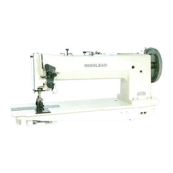
- Page 1 GC20698-5/-6/-7/-8 Compound-Feed, Heavy Duty Lockstitch Sewing Machine Instruction Manual Parts Catalog SHANGHAI BIAOZHUN HAILING SEWING MACHINERY CO., LTD.
-
Page 2: Table Of Contents
—INDEX— OPERATION INSTRUCTION PRECAUTIONS BEFORE STARTING OPERATION ……………………..…………………..………..SPECIFICATIONS .……………………………………………………………………………...….……… SETTING UP THE MACHINE………………………...…………………………………………..……… OILING…………………………………………………………………………………………….….……... NEEDLE…………………………………………………………………………………………….….……. THREAD……..…………………………………………………………………………………….…….… WINDING THE LOWER THREAD ON THE BOBBIN…………………………………………………… REMOVE AND INSERT THE BOBBIN……………………………………………………..…….…….… THREADING THE NEEDLE….……..………………………………………………...………………..… REGULATING THE THREAD TENSION…...………………………………….………………….……… ADJUSTMENT OF THE STITCH LENGTH..…………………………………………………….…..…… ADJUSTMENT OF THE PREESURE ..…………………………………………………….…..………….. - Page 3 D. STITCH REGULATOR MACHANISM…………………………………………………..…………… HOOK SHAFT MECHANISM..…………………………………………………………………….…..… THREAD TENSION REGULATOR MACHANISM……..…………………………………….………..G. PARTS FOR SINGEL NEEDLE………………………………………………………………….…..… H. PARTS FOR TWIN NEEDLE………………………………………………………………….………..… SPECIAL PARTS FOR 20”………………………………………………………………………………… ACCESSORIES…………………………………………………………………………………………….
-
Page 4: Precautions Before Starting Operation
3) Precautions for operating conditions (1)Avoid using the machine at abnormally high temperatures (35℃ or higher) or low temperatures (5℃ or lower). (2)Avoid using the machine in dusty conditions. 2. SPECIFICATIONS GC20698-5 GC20698-6 GC20698-7 GC20698-8 MAX. SPEED (s.p.m.) 1,200 MAX. STITCH (mm) MAX. -
Page 5: Setting Up The Machine
USE FOR:Tent,Sailcloth,Rubberized,Fabrics,Heavy Synthetic, Heavy Upholstery Materials,Fiber Plate,Leather,Etc. 3. SETTING UP THE MACHINE (Fig. 1) Setting up the machine on the table after removed two pieces of supporting bolts(A)under the bed. Fig.1 4. OILING (Figs. 2, 3, 4 & 5) Oil should be applied at each of the place designated by arrows in Figs. 2, 3, 4&5. Fig.3 Fig.2 Fig.4... -
Page 6: Needle
5. NEEDLE ( Figs. 7 & 8 ) HIGHLEAD GC20698-5,-6,-7,-8 series machines are set up to use standard needle of DY×3 ( standard No. 24 ) ·SY5213·794. The size of needle to be used should be determined by the size of thread, type and thickness of the sewing materials. -
Page 7: Thread
6. THREAD ( Fig. 9 ) Normally, left twisted thread is used for upper ( needle ) thread. ( But, for left side needle of twin-needle machine, it can be finished in fine results with right twisted thread ) . Left Twist Rigth Twist Fig.9... -
Page 8: Threading The Needle
9. THREADING THE NEEDLE ( Figs. 14 & 15 ) Pass the thread from thread guide ( 1 ) -eyelet ( 2 ) -tension disc ( 3 ) -tension thread guide ( 4 ) –guide ( 5 ) -thread take-up spring ( 6 ) –guide ( 7 ) -take-up lever ( 8 ) –guide ( 7 ) -lower guide ( 9 ) -self threading needle bar thread guide (... -
Page 9: Adjustment Of The Stitch Length
11. ADJUSTMENT OF THE STITCH LENGTH ( Fig. 18 ) The length of stitch is regulated by pressing down the button ( 1 ) with left hand, while turning the machine pulley ( 2 ) slowly with right hand in the condition of setting the top of button ( 1 ) to the feed eccentric. To increase the length of stitch, turn the machine pulley over toward you. -
Page 10: Width Of Zigzag And Length Of Stitch
14. RELATIVE POSITION OF VIBRATING AND LIFTING PRESSER BAR, OF THE NEEDLE AND THE NEEDLE HOLE OF THE FEEDER ( Figs. 21 & 22 ) The distance between the vibrating presser bar ( 1 ) and lifting presser bar(2), after adjusting the feed eccentric so that there is no feed movement of the needle bar, should be 15.5 mm (... -
Page 11: Timing Between The Hook And The Needle
16. TIMING BETWEEN THE HOOK AND THE NEEDLE ( Fig. 26 ) Set the feed eccentric with the button at no feeding position, and confirm the length between vibrating and lifting presser bar should be 15.5 mm. If the needle bar and sewing hook are correctly timed, the point of the hook will be at the center of the needle when the needle raised 3.8 mm + 0.5 mm from the lowest point. -
Page 12: Adjustment Of Bobbin Case Opener
17. ADJUSTMENT OF BOBBIN CASE OPENER ( Fig. 28 ) ( 1 ) Turn the machine pulley or hand wheel ( GC20698-6,-8 series machine ) until the top of the opener is located at the distance from the needle plate. -
Page 13: Timing Of The Vibrating And Lifting Presser Feet
19. TIMING OF THE VIBRATING AND LIFTING PRESSER FEET ( Fig. 32 ) The amount of lift of the vibrating and lifting presser feet should be regulated according to the thickness of materials being sewn. The feet should lift just enough to clear the materials. As a rule, the vibrating and lifting presser feet should lift an equal height, but some grades of work may require that they lift an unequal height. -
Page 14: Adjustment Of The Thread Controller Spring
21. ADJUSTMENT OF THE THREAD CONTROLLER SPRING ( Fig. 34 ) For more controller action on the thread, loosen the set screw ( 1 ) at the right of the controller and set the stop lever, and for less action set the stop higher. To strengthen the action of the controller spring on the thread, loosen the spring stud screw (... -
Page 15: To Re-Engage The Safety Clutch
( 4 ) Loosen the three screws in the arm shaft bushing ( 5 ) and remove the bushing ( 6 ) . ( 5 ) Lift the belt up through the arm cap hole after removed the bushing ( 6 ) as far as possible and draw it out through the space normally occupied by the bushing. -
Page 16: Adjustment Of The Oiling For The Hook Saddle
24. ADJUSTMENT OF THE OILING FOR THE HOOK SADDLE ( Fig. 41 ) Loosen the screw for the oil adjustment dial ( 3 ) and adjust oil supply by turning the oil adjustment dial ( 2 ) . Maximum oil supply at the directly in line of the point mark ( 1 ) on the hook saddle and the center line of the dial (... -
Page 17: Arm Bed And It's Accessories
A.ARM BED AND ITS ACCESSORIES - 14 -... - Page 18 A.ARM BED AND ITS ACCESSORIES Fig. Parts Description Remarks Nos. Nos. HE924B7101 Foot lifter lifting lever latch handle HA100B2110 Set screw HE913B8001 Collar (upper) H7214H8001 screw HE915B8001 Foot lifter lifting lever latch spring HE916B8001 Collar (lower) HA100C2170 Set screw HE917B8001 Foot lifter lifting lever latch HE918B8001 Foot lifter lifting lever...
- Page 19 A.ARM BED AND ITS ACCESSORIES Fig. Parts Description Remarks Nos. Nos. HE943B8001 Bed slide (right) HE946B8001 Bed slide stop HE009H8001 Bed slide stop spring HE944B8001 Bed plate (front) HE013H8001 Screw HE957B8001 Arm cross shaft bushing HE014C8001 Oil wick HE040D8001 Set screw HE958B8001 Arm cross shaft gear HE017G8001...
-
Page 20: Arm Shaft Mechanism
B.ARM SHAFT MECHANISM - 17 -... - Page 21 B.ARM SHAFT MECHANISM Fig. Parts Description Remarks Nos. Nos. HE904C8001 Arm shaft HE905C8001 Take-up lever HE906C8001 Take-up lever hinge stud HE907C8001 Oil wick HE020C8001 Set screw HA100B2150 HE908C8001 Take-up lever driving stud HE035C8001 Oil wick HE909C8001 Needle bar connecting link HE910C8001 Needle bar crank HA100C2070...
- Page 22 B.ARM SHAFT MECHANISM Fig. Parts Description Remarks Nos. Nos. HE007C8001 Machine pulley adjusting screw HE921C8001 Hook driving shaft lock stud H4107D0672 Spring HE922C8001 Socket H601016100 Stop HE923C8001 Hook driving shaft lock ratchet HE035G8001 Set screw HE034G8001 Set screw HE924C8001 Safety clutch pulley H3205C0661 Spring flange HE021G8001...
-
Page 23: Presser Foot Machanism
C.PRESSER FOOT MECHANISM - 20 -... - Page 24 C.PRESSER FOOT MECHANISM Fig. Parts Description Remarks Nos. Nos. HE904D8001 Needle bar rock frame HE905D8001 Needle bar rock frame hinge stud HE035C8001 Oil wick HE009G8001 Set screw HE907D8001 Needle bar connection stud HE041C8001 Oil wick HE119E8001 Pinch screw for 70022 HE908D8001 Needle bar HE909D8001...
- Page 25 C.PRESSER FOOT MECHANISM Fig. Parts Description Remarks Nos. Nos. HE929D8001 Set screw for vibrating presser foot HE930D7101 Needle bar frame rock shaft H3100F2270 Needle bar rock frame slide block HE027E8001 Screw stud HE028E8001 Set screw HE933D8001 Needle bar rock frame rock shaft crank HE038E8001 Pinch screw HE934D8001...
-
Page 26: Stitch Regulator Machanism
D.STITCH REGULATOR MECHANISM - 23 -... - Page 27 D.STITCH REGULATOR MECHANISM Fig. Parts Description Remarks Nos. Nos. HE946E7101 Feed driving eccentric HE905E8001 Flange HE906E8001 Set screw HE907E8001 Set screw HE908E8001 Friction plate HE909E8001 Stop screw HA100B2110 Set screw HE910E8001 Feed driving eccentric adjusting disc HE911E8001 Spring HE912E8001 Collar HE035G8001 Position screw HE023C8001...
- Page 28 D.STITCH REGULATOR MECHANISM Fig. Parts Description Remarks Nos. Nos. HE035C8001 Oil wick HE941E8001 HE931E8001 Stop screw HE932E8001 Feed reversing lever slide block HE933E8001 Hinge screw HE934E8001 Feed reversing link HE935E8001 Spring and treadle connecting link HE936E8001 Hinge screw nut HE937E8001 Hinge screw HE035C8001 Oil wick...
-
Page 29: Hook Shaft Mechanism
E.HOOK SADDLE MECHANISM - 26 -... - Page 30 E.HOOK SADDLE MECHANISM Fig. Parts Description Remarks Nos. Nos. HE904F8001 Oil gauge HE039J8001 Oil gauge guide HE905F8001 Bobbin case opener lever HE906F8001 Bobbin case opener lever hinge stud HE018J8001 Oil wick HE020J8001 Oil wick vinyl tube HE907F8001 Bobbin case opener H005004060 Washer HE909F8001...
- Page 31 E.HOOK SADDLE MECHANISM Fig. Parts Description Remarks Nos. Nos. HE045G8001 Set screw HE049J8001 Washer HE050J8001 Hook saddle screw HE058G8001 Feed lifting cam HE017G8001 Set screw HE010G8001 Oil wick HE040D8001 Set screw HE922F8001 Hook driving shaft HE923F8001 Hook driving shaft bushing (center) HE007G8001 Oil pad HE034G8001...
-
Page 32: Thread Tension Regulator Machanism
F.THREAD TENSION REGULATOR MECHANISM - 29 -... - Page 33 F.THREAD TENSION REGULATOR MECHANISM Fig. Parts Description Remarks Nos. Nos. HE904G8001 Presser bar spring (flat) HE905G8001 Presser bar spring (auxiliary) H005006080 Presser bar spring support screw washer HE907G8001 Presser bar spring support screw HE908G8001 Presser bar spring regulating screw HE048D8001 Presser bar lifting bracket guide screw HE933G7101 Bobbin complete...
- Page 34 F.THREAD TENSION REGULATOR MECHANISM Fig. Parts Description Remarks Nos. Nos. H3108B0692 Felt HE929G8001 Thread controller spring HE930G7101 Thread controller spring stop - 31 -...
-
Page 35: Parts For Singel Needle
G.PARTS FOR SINGLE NEEDLE - 32 -... - Page 36 G.PARTS FOR SINGLE NEEDLE Fig. Parts Description Remarks Nos. Nos. HF204D8001 Needle bar rock frame HF205D8001 Needle bar H4915J8001 Set screw HF206D8001 Thread guide HF210B8001 Bed plate(left) HF211B8001 Bed plate(right) HE005H8001 Throat plate screw HE006H8001 Throat plate position screw HF209B8001 Throat plate HF205E8001 Feed dog...
-
Page 37: Parts For Twin Needle
H. PARTS FOR TWIN NEEDLE 3/8" 3/4" 1/4" 1" 1·1/4" 1·1/2" 1/2" 7/8" 1·3/4" 3/8" 3/4" 1/4" 1" 1·1/4" 1·1/2" 1/2" 7/8" 1·3/4" 3/8" 3/4" 1/4" 1/2" 1" 1·1/4" 1·1/2" 7/8" 1·3/4" 3/8" 3/4" 1·1/2" 1/2" 7/8" 1/4" 1" 1·1/4" 1·3/4"... -
Page 38: Special Parts For 20
I.SPECIAL PARTS FOR 20" - 35 -... - Page 39 I.SPECIAL PARTS FOR 20" Fig. Parts Description Remarks Nos. Nos. HF410B8001 Foot lifting lever HF404C8001 Arm shaft HF404D7101 Needle bar frame rock shaft HF404E8001 Feed driving rock shaft HF404F8001 Hook driving shaft - 36 -...
-
Page 40: Accessories
J.ACCESSORIES - 37 -... - Page 41 J.ACCESSORIES Fig. Parts Description Remarks Nos. Nos. HE933F7101 Bobbin HA300J2070 Screw driver (large) HA300J2200 Screw driver (middle) HA300J2210 Screw driver (small) HB00001040 Wrench 4.0 mm HB00001030 Wrench 3.0 mm HB00001025 Wrench 2.5 mm HB00001015 Wrench 1.5 mm HA300J2220 Double head wrench HE905H8001 Oil pan 016250...
- Page 42 SHANGHAI BIAOZHUN HAILING SEWING MACHINERY CO., LTD. ADD: NO.850 Shulin Road, Songjiang District Shanghai, P.R.China Zip Code: 201612 Overseas Business: TEL: 86-21-64853303 FAX: 86-21-64854304 E-mail:sales@highlead.com.cn http://www.highlead.com.cn The description covered in this manual is subject to change for improvement of the commodity without notice 2018.4. Printed...
Need help?
Do you have a question about the GC20698-6 and is the answer not in the manual?
Questions and answers