
Subscribe to Our Youtube Channel
Related Manuals for HIGHLEAD GC20618 Series


Summary of Contents for HIGHLEAD GC20618 Series
- Page 1 GC20618Series Compound-Feed,Heavy Material Lockstitch Sewing Machine Instruction Manual Parts Catalog SHANGHAI BIAOZHUN HAILING SEWING MACHINERY CO., LTD.
-
Page 2: Table Of Contents
CONTENTS PRECAUTIONS BEFORE STARTING OPERATION ------------------------------------- PREPARATION FOR OPERATION Power cable connection ------------------------------------------------------------------------ Connection of control box ---------------------------------------------------------------------- Adjustment of needle bar stop position --------------------------------------------------------- CAUTIONS ON USE 1. Oiling (1) --------------------------------------------------------------------------------------- 2. Oiling (2) --------------------------------------------------------------------------------------- 3. Oiling condition --------------------------------------------------------------------------------- 4. - Page 3 PARTS CATALOG 1. Arm bed its accessories ------------------------------------------------------------------------- 2. Thread tension regulator mechanism ------------------------------------------------------------ 3. Arm shaft mechanism --------------------------------------------------------------------------- 4. Upper shaft & presser foot mechanism -------------------------------------------------------- 5. Needle bar & thread take-up lever mechanism ------------------------------------------------- 6. Stitch regulator mechanism -------------------------------------------------------------------- 7.
-
Page 4: Precautions Before Starting Operation
PRECAUTIONS BEFORE STARTING OPERATION 1. Safety precautions 1) When turning the power on, keep your hands and fingers away from the area around/under the needle and the area around the pulley. 2) Power must be turned off when the machine is not used, or when the operator leaves his/her seat. 3) The power must be turned off before tilting the machine head, installing or removing the “V”... -
Page 5: Preparation For Operation
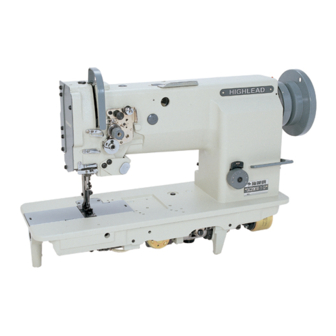
PREPARATION FOR OPERATION verall view of assembled sewing machine 1. Power cable connection 1) Connection to Power Supply When connecting the power supply connector to the control box, the connector should be completely plugged in the proper receptacle after confirming the connector type and matching direction. In case of three-phase electrical power system, the “U”... -
Page 6: Connection Of Control Box
wrapping insulating tape on the wires. CAUTION: The power switch must be Turned off before connecting the lamp. B. When the illuminating lamp is not used, the end of the lamp leads must be insulated as (a) or (b) as shown in the figure on right side. -
Page 7: Cautions On Use
tool” in the hole” A”, then remove the tool. Adjust of “Down” position When the pedal is “Neutral” the machine stops at “Down” position. If the marks deviate large than 5 mm, adjust as follows. a) Disconnect the plug (12 pins) of cable from the machine head b) Run the machine and stop at “Down”... -
Page 8: Adjustment Of Oiling To Rotating Hook
4. Adjustment of oiling to rotating hook Cautions on operation a) When the power is turned on or off, keep foot away from the pedal. b) It should be noted that the brake may not work when the power is interrupted or power failure occurs during sewing machine operation. -
Page 9: Selection Of Thread
of thread and tighten the screw to decrease length of thread. 3. Selection of thread It is recommended to use “S” twist thread in the left needle (viewed from front), and “Z’ twist thread in the right needle. When discriminate use of needle threads is impossible, use “Z”... -
Page 10: Adjustment Of Feed (Stitch) Length And Stitch Reversing (Touch-Back)
5. Adjustment of feed (stitch) length and stitch reversing (touch back) Note: To make feed (stitch) length smaller, depress the feed reverse lever and set the feed length setting dial to a desired position Touch-back button . . . Direction of stitching can be reversed by depressing this button. Stitching goes on in reversed direction while the button is held down, and returns to forward direction when the button is released. -
Page 11: Tension Adjustment Of Bobbin Threads
9. Balance of thread tension 8. Tension adjustment of bobbin threads 10. Needle thread tension ·Needle thread tension should be adjusted in reference to bobbin thread tension. ·To adjust needle thread tension, turn each tension adjusting nut. ·Needle thread tension can be also adjusted for special fabric and thread by changing intensity and movable range of slack thread adjusting spring. -
Page 12: Adjustment Of Feed Dog Height
Positioning of hook point (1) When the needle is at DOWN position, the smaller Crossed helical gears on the right side and left side should be engaged with the large wheel so that the “S” screw of the former gear comes on the front side, and that of the latter gear on the reverse side. -
Page 13: Relationship Between Rotating Hook Motion And Take-Up Lever Motion
After the adjustment, tighten the feed bar set screw. The feed dog height is factory-adjusted to 1.2mm 14. Relationship between rotating hook motion and take-up lever motion When the timing belt (toothed belt) was removed for its replacement, for example, the relationship between rotating hook motion and take-up lever motion should be adjusted as follows: a) Turn the balance wheel and stop when the take-up... -
Page 14: Safety Clutch Device
h) After the completion of adjustment, fully tighten the screws A , B and C. At this time make certain that needle can enter the feed dog needle hole at the center of the hole. 17. Safety clutch device: Safety clutch device is installed to prevent the hook and cog belt from damage in case the thread is caught into the hook when the machine is loaded... -
Page 15: Upper Feed Adjustment (Needle Side)
Force applied to the safety clutch. The force applied to the safety clutch is the smallest when the white mark of the eccentric pin faces the center of the lower shaft. The force proportionally increases as the white mark faces the outside. b) To adjust the force slide the timing belt, loosen the set screw, and turn the eccentric pin. -
Page 16: Installation Of Movable Knife
21. Installation of movable knife Installation of movable knife Turn the balance wheel and lower the needle bar to the lowest position. Push the cam follower crank so that the cam roller enters into the thread trimmer cam groove. Turn the balance wheel until the black mark point on the arm meets the white mark point on the balance wheel. -
Page 17: Adjustment Of Needle Threads Tension Release Assembly
the arm. Note: To adjust, loosen two thread trimmer cam clamp screws A. Adjustment of needle threads tension release assembly a. Turn the balance wheel by hand until the needles reach the lowest position. b. Maintaining the needle position, depress the cam follower crank and put the cam roller into the groove of thread trimmer cam. -
Page 18: Sharpening Of Fixed Knife
b. Turn the vertical position adjusting screw B to adjust meshing pressure and then righter the hexagon socket head cap screw A. Note: Since excess pressure causes large torque to the thread trimming mechanism and trimming failure, adjust it so that thread can be trimmed with minimum pressure. -
Page 19: Specifications
Push the cam follower crank K so that the cam roller enters into the cam groove. Turn the connecting rod L and adjust the clearance between the cam roller and the cam groove surface L as small as possible, and tighten the nuts G and H. iii. -
Page 20: Parts Catalog 1. Arm Bed Its Accessories
A.ARM BED AND ITS ACCESSORIES — 17 —... - Page 21 A.ARM BED AND ITS ACCESSORIES Fig. Part No. Name Description HA300B2090 Rubber plug HA300B2170 Screw SM11/64(40)×8 H4716B8001 Oil guard plate H4717B8001 Thread take-up cover H4715B8001 Rubber plug φ13 H4718B8001 Side cover (left) H2000B2010 Rubber plug φ13 H4919B8001 Side cover (right) H4719B8001 Side cover (right) HA700B2060 Screw SM11/64(40)×8...
-
Page 22: Thread Tension Regulator Mechanism
B.THREAD TENSION REGULATOR MECHANISM — 19 —... - Page 23 B.THREAD TENSION REGULATOR MECHANISM Fig. Part No. Name Description H3221B6811 Screw SM9/64(40)×3 H3221B3142 Tension releasing plate H3221B6812 Tension releasing spring H4705C8001 Screw SM9/64(40)×4.2 H4706C8001 Lever HA7311C306 Screw SM9/64(40)×4.5 H4707C8001 Mounting plate H007013050 Stop ring GB/T896 5 H3221B6820 Mounting plate HA300C2030 Screw H3221B6810 Nut SM11/64(40)...
- Page 24 B.THREAD TENSION REGULATOR MECHANISM Fig. Part No. Name Description H32481B121 Thread tension stud H4805C8001 Thread tension stud H3230K0751 Screw SM11/64(40)×10 H3221B6817 Pin H3221B6818 Tension releasing pin H4916B8001 Tension releasing pin H3200B2100 Screw SM9/64(40)×6.5 H3221B6819 Stopper — 21 —...
-
Page 25: Arm Shaft Mechanism
C.ARM BED AND ITS ACCESSORIES — 22 —... - Page 26 C.ARM BED AND ITS ACCESSORIES Fig. Part No. Name Description HA307C0662 Set screw SM1/4(40)×7 H4706D8001 Crank HA105D0662 Screw SM1/4(40)×3.5 HA100C2060 Set screw SM9/32(28)×14 HA100C2070 Screw SM9/32(28)×13 H32111B204 Arm shaft bushing (left) H4708D8001 Screw SM1/4(24)×13 H32111B104 Felt H4709D8001 Arm shaft H3205C0661 Spring flange HA113F0684 Screw SM15/64(28)×8.5 H3205C1021 Belt pulley (upper)
-
Page 27: Upper Shaft & Presser Foot Mechanism
D.UPPER SHAFT & PRESSER FOOT MECHANISM — 24 —... - Page 28 D.UPPER SHAFT & PRESSER FOOT MECHANISM Fig. Part No. Name Description H4705E8001 Feed lifting rock shaft H4706E8001 Screw SM1/4(24)×7 H4707E8001 Bushing HS91165206 Nut M6×0.75 H4709E8001 Lever H3115F0671 Screw SM1/4(28)×16 H2013J0065 Washer H2014J0066 Connecting rod H2000J2100 Bolt H4713E8001 Oil pipe & wick complete H20111C106 Spring H007009250 C-type stop ring GB/T894.1 25...
- Page 29 D.UPPER SHAFT & PRESSER FOOT MECHANISM Fig. Part No. Name Description H4718E8001 Screw SM11/64(32)×6 H2004J0662 Screw SM1/4(40)×5 H4719E8001 Link HA100E2150 Screw SM11/64(40)×10 H4722E8001 Washer H4721E8001 Bell crank guide H4753E8001 Screw SM11/64(40)×14.5 H4708D8001 Screw SM1/4(24)×13 H4757E8001 Lifting presser foot H3100G2110 Lifting presser foot —...
-
Page 30: Needle Bar & Thread Take-Up Lever Mechanism
E.TAKE-UP THREAD AND ARM SHAFT MECHANISM — 27 —... - Page 31 E.TAKE-UP THREAD AND ARM SHAFT MECHANISM Fig. Part No. Name Description H24211DN05 Oil wick H4706F8001 Needle bar guide bracket stud H4707F8001 Screw SM5/16(28)×10.4 HA100C2020 Screw SM15/64(28)×10 H24211DN05 Oil wick E06 H24211DM05 Thread take-up lever support stud H4712F8001 Thread take-up lever H2405D1112 Thread take-up slide brock H24211D405 Oil wick H24211D305 Plug...
- Page 32 E.TAKE-UP THREAD AND ARM SHAFT MECHANISM Fig. Part No. Name Description H32311D406 Oil wick H3129F0691 Screw SM3/32(56)×2.5 HA100C2170 Screw SM1/8(44)×4.5 H3129F0693 Thread guide H32132D104 Screw SM9/64(40)×3 H4739F8001 Needle clamp(1//4) H4740F8001 Needle HA700F2100 Screw SM11/64(40)×7 — 29 —...
-
Page 33: Stitch Regulator Mechanism
F.STITCH REGULATOR MECHANISM — 30 —... - Page 34 F.STITCH REGULATOR MECHANISM Fig. Part No. Name Description H4706G8001 Feed regulator cam HA113F0684 Screw SM15/64(28)×8.5 H3200F2020 Screw SM15/64(28)×12 H4707G8001 Link HA100G2070 Eccentric shaft H4709G8001 Reverse stitch shaft (upper) H4909G8001 Reverse stitch shaft (upper) H3207F0671 Arm H4905G8001 Arm HA800F2020 Screw HA100F2110 Spring Washer HA113F0684 Screw H4711G8001 Reverse sewing lever H4906G8001 Reverse sewing lever...
-
Page 35: Lower Shaft & Feed Rock Shaft Mechanism
G.LOWER SHAFT & FEED ROCK SHAFT MECHANISM — 32 —... - Page 36 G.LOWER SHAFT & FEED ROCK SHAFT MECHANISM Fig. Part No. Name Description H4706H8001 Lower shaft bushing (left) H4707H8001 Oil wick H4708H8001 Lower shaft H4710H8001 Feed eccentric cam H3205H0654 Screw SM1/4(40)×5 H4712H8001 Lower shaft bushing (right) H4713H8001 Oil wick H007013050 Stop ring GB/T896 5 H4714H8001 Spring H4715H8001 Push button...
- Page 37 G.LOWER SHAFT & FEED ROCK SHAFT MECHANISM Fig. Part No. Name Description G44 HA104G0012 Screw SM3/16(28)×12 H4905H8001 Feed connection crank (left) H3205G1032 Feed connection crank (left) H32243G205 Feed bar shaft H3205G0662 Oil wick H32211G205 Bolt SM1/8(40)×7 H429050050 Bolt GB/T78 M5×5 H32211GC05 Feed bar H4805H8001 Feed bar H4942H8001 Feed bar...
-
Page 38: Hook Saddle Mechanism
H.HOOK SADDLE MECHANISM — 35 —... - Page 39 H.HOOK SADDLE MECHANISM Fig. Part No. Name Description H3304I0651 Hook saddle (right) H4906I8001 Hook saddle (right) H3207I0661 Screw SM15/64(28)×22 H3207I0662 Bushing H4707I8001 Screw SM1/4(40)×4 H4706I8001 Hook driving gear (large) H4708I8001 Screw SM1/4(40)×6.5 H4709I8001 Screw SM1/4(40)×5 H4705I8001 Hook driving gear (small) H3306I0067 Bobbin H4912I8001 Bobbin BO-B872(A)
-
Page 40: Knife Mechanism (Ⅰ)
I.UPPER FEED ROCK SHAFT MECHANISM — 37 —... - Page 41 I.UPPER FEED ROCK SHAFT MECHANISM Fig. Part No. Name Description H4905J8001 Screw H4906J8001 Bolt SM11/64(40)×12 H4907J8001 Trimming knife holder H4908J8001 Screw SM9/64(40)×4 H4909J8001 Fixed blade H4914B8001 Screw SM9/64(40)×4 H4911J8001 Moved knife H4912J8001 Screw SM1/8(44)×9.2 H4913J8001 Screw SM9/64(40)×4.5 H4914J8001 Spring plate H4915J8001 Screw SM3/32(56)×3.8 H4916J8001 Reversing spring...
-
Page 42: Knife Mechanism (Ⅱ)
J.KNIFE MECHANISM — 39 —... - Page 43 J.KNIFE MECHANISM Fig. Part No. Name Description HA300C2020 Screw SM11/64(40)×8 H4915K7101 Thread releading bracket H4918K8001 Spring H4919K7101 Thread releading plate H2400I2040 Screw SM11/64(40)×5 HA300B2170 Screw SM11/64(40)×8 H4923K7101 Flexible wire complete H4912K8001 Arm H4913K8001 Bolt SM15/64(28)×12.5 H4945K8001 Spring H4950K8001 Screw SM11/64(40)×3.6 H4949K8001 Roller H4952K8001 Screw SM3/16(28)×5...
- Page 44 J.ARM BED AND ITS ACCESSORIES Fig. Part No. Name Description H4964K8001 Shaft H4963K8001 Shaft H4985K8001 Screw SM11/64(40)×4 H3405D0663 Ball joint (right) H3205G1114 Screw M4×4 H4934K8001 Cam HA710E0692 Screw SM1/4(40)×9.5 H4932K8001 Cam H4986K8001 Spring H411050160 Screw GB/T819.1 M5×16 H2012N0652 Screw SM1/4(24)×16 H4983K8001 Screw SM1/4(24)×13 H4967K8001 Screw...
-
Page 45: Touch Back Mechanism & Detector Mechanism
K.TOUCH BACK MECHANISM & DETECTOR MECHANISM — 42 —... - Page 46 K.TOUCH BACK MECHANISM & DETECTOR MECHANISM Fig. Part No. Name Description H4905L7101 Touth switch complete H4918L8001 Screw HA700Q0030 Holder H4922L8001 Holder H3205J0662 Ball bearing H007009300 Retaining ring C-type GB/T894.1 30 HA700R0060 Washer HA700R0050 Support spring HA700R0040 Spacer B H4928L8001 Speed command disk F20 (up) HA700R0030 Spacer A H4930L8001...
-
Page 47: Oil Lubrication Mechanism
L.OIL LUBRICATION MECHANISM — 44 —... - Page 48 L.OIL LUBRICATION MECHANISM Fig. Part No. Name Description H32175B304 Felt H4705J7101 Oil pipe complete H3204K0011 Oil reservoir complete H411040160 Screw GB/T819.1 M4×16 H4707J8001 Holder H4708J8001 Oil pipe Ф 3 x 1 x 400 H4709J8001 Oil pipe Ф 5 x 1 x 360 H4711J7101 Oil reservoir complete H4713J8001 Holder L10 HA7311CC06 Screw...
- Page 49 L.OIL LUBRICATION MECHANISM Fig. Part No. Name Description H4731J8001 Holder HA300C2030 Screw — 46 —...
-
Page 50: Accessories
M.ACCESSORIES — 47 —... - Page 51 M.ACCESSORIES Fig. Part No. Name Description H32175B304 Felt H4705J7101 Oil pipe complete H3204K0011 Oil reservoir complete H411040160 Screw GB/T819.1 M4×16 H4707J8001 Holder H4708J8001 Oil pipe Ф 3 x 1 x 400 H4709J8001 Oil pipe Ф 5 x 1 x 360 H4711J7101 Oil reservoir complete H4713J8001 Holder L10 HA7311CC06 Screw...
- Page 52 M.ACCESSORIES Fig. Part No. Name Description H4731J8001 Holder HA300C2030 Screw — 49 —...
-
Page 53: Gauge Parts Liat
Gauge Parts List Presser Foot Presser Foot Gauge Size Needle Plate Needle Clamp Feed Dog Slide Plate(L) Slide Plate(R) (Inside) (Outside) GC20618-2 1/8(3.2mm) H4737B8001 H4741F8001 H4758E8001 H4750F8001 H4745H8001 H4732B8001 H4733B8001 5/32(4mm) H4738B8001 H4742F8001 H4759E8001 H4751F8001 H4746H8001 H4732B8001 H4733B8001 3/16(4.8mm) H4739B8001 H4743F8001 H4760E8001 H4752F8001 H4747H8001 H4732B8001 H4733B8001 1/4(6.4mm) H4734B8001 H4737F8001 H4757E8001 H4739F8001 H4744H8001 H4732B8001 H4733B8001 5/16(8mm) H4740B8001 H4744F8001 H4761E8001 H4753F8001 H4748H8001 H4746B8001 H4733B8001... - Page 54 SHANGHAI BIAOZHUN HAILING SEWING MACHINERY CO., LTD. ADD: NO.850 Shulin Road, Songjiang District Shanghai, P.R.China Zip Code: 201612 Overseas Business: TEL: 86-21-64853303 FAX: 86-21-64854304 E-mail:sales@highlead.com.cn http://www.highlead.com.cn The description covered in this manual is subject to change for improvement of the commodity without notice 2016.7. Printed...
Need help?
Do you have a question about the GC20618 Series and is the answer not in the manual?
Questions and answers