
Subscribe to Our Youtube Channel
Related Manuals for Unipower Sageon Micro Power Module


Summary of Contents for Unipower Sageon Micro Power Module
- Page 1 ® Sageon Micro Power Module Product Manual UNIPOWER, LLC 65 Industrial Park Rd Dunlap, TN 37327 Phone: +1-954-346-2442 PM 990-4207-00, Rev 6 Toll Free: 1-800-440-3504 Web site – www.unipowerco.com...
- Page 2 Power shelf into the rack without either the Controller or the Micro Sageon rectifiers in place. Seismic Statement. The Sageon Micro Power Module and/or the Rack Mounted Shelf design does not include, either in the construction or in the assembly, the ability to withstand the lateral seismic forces or seismic loading induced by earthquakes.
- Page 3 UNIPOWER, ask the delivering carrier to send the packages back to UNIPOWER at the delivering carrier’s expense. Be sure that the equipment is properly packaged for shipment. If repair is necessary, UNIPOWER will invoice you for the repair so that you may submit the bill to the delivering carrier with your claim form.
- Page 4 Sageon Micro Power Module Manual NAMEPLATE A UNIPOWER product is identified by a nameplate that includes model number, part number, and serial number information, as appropriate. Please include this information, shown in italic in the label drawing below, in all correspondence with UNIPOWER.
- Page 5 The drawings supplement the provided descriptions and procedures. Thank you for purchasing the Sageon Micro Power Module. We at UNIPOWER are proud of the quality of our products and welcome any suggestions to further improve our design to fit your needs.
-
Page 6: Table Of Contents
Front Matter Sageon Micro Power Module Manual TABLE OF CONTENTS GENERAL WARNING ............................1-1 PRODUCT SUPPORT ..........................1-1 CONFIGURATION ............................2-1 GENERAL DESCRIPTION ......................... 2-1 SYSTEM DESCRIPTION ........................... 2-1 2.2.1 Front View ............................... 2-1 2.2.2 Rear View ..............................2-4 INSTALLATION..............................3-1 MOUNTING THE POWER SHELF ...................... - Page 7 Front Matter Sageon Micro Power Module Manual APPENDIX A – SETTING UP NETWORK INTERFACES ................7-1 PROGRAMMING IP ADDRESSES USING DEVICE INSTALLER SOFTWARE ........7-1 7.1.1 Preparations for local address set up ......................7-1 7.1.2 Local IP address set up procedure ......................7-1 7.1.3...
-
Page 8: General Warning
Phone: +1-954-346-2442 Toll Free: 1-800-440-3504 Web site – www.unipowerco.com When contacting UNIPOWER, please be prepared to provide: The product model number, spec number, S build number, and serial number - see the equipment nameplate on the front panel Your company’s name and address... -
Page 9: Configuration
Configuration Sageon Micro Power Module Manual 2. CONFIGURATION 2.1 GENERAL DESCRIPTION RT9 Power shelf systems are turn-key DC uninterruptible power supply solutions (DC UPS) for powering 24VDC or 48VDC telecommunications and industrial equipment. The Power shelf provides integrated battery management functions for a range of battery types (VRLA, flooded Lead-acid, NiCad, Ni-MH, Li-polymer) to enable easy commissioning of a DC UPS or it can be used as a standalone DC source when no batteries are used. -
Page 10: Figure 2.3 System Blocks (4Ru Series)
Configuration Sageon Micro Power Module Manual Figure 2.3 System blocks (4RU Series) Figure 2.4 System blocks (5RU Series) PM990-4207-00, Rev 6... -
Page 11: Figure 2.5 System Blocks (6Ru Series)
Configuration Sageon Micro Power Module Manual Figure 2.5 System blocks (6RU Series) Figure 2.6 System blocks(7RU Series) PM990-4207-00, Rev 6... -
Page 12: Rear View
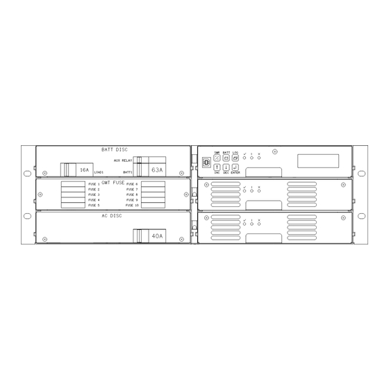
Configuration Sageon Micro Power Module Manual Rack mounting magazine Rectifier module Battery (& load) distribution module Controller AC distribution module (option on some systems) 2.2.2 Rear View Figure 2.7 Rear view of connections Controller backplane & interface connections Battery (& load) switched connections Battery (&... -
Page 13: Figure 2.8 Connections On Controller Backplane
Configuration Sageon Micro Power Module Manual Figure 2.8 Connections on Controller backplane Remote communications module connection (14-way ribbon) Auxiliary peripheral module (relays, battery cell monitor, etc) connection (16-way ribbon)* Battery (& load) distribution module connection** (34-way ribbon) Ambient temperature sensor connection (sensor P/N 385-5941-03) -
Page 14: Installation
Installation Sageon Micro Power Module Manual 3. INSTALLATION 3.1 MOUNTING THE POWER SHELF The Power shelf is mounted into a standard 19” rack using 12-24 screws. A minimum of 4 screws are required to secure the Power shelf into the rack. It is recommended to initially install the Power shelf into the rack without either the Controller or the RT9 rectifiers in place. -
Page 15: Overview Of External Wiring Connections
Installation Sageon Micro Power Module Manual Similarly, the energy hazard associated with the batteries connected to the DC bus must be addressed through the use of appropriately insulated tools and other measures to prevent accidental short circuits to the DC bus. -
Page 16: Figure 3.3 Typical Powershelf Internal Schematic Diagram
Installation Sageon Micro Power Module Manual Figure 3.3 Typical Powershelf internal schematic diagram PM990-4207-00, Rev 6... -
Page 17: Mains Connections
Commissioning Sageon Micro Power Module Manual The switched battery cables (negative in a –48V system) terminate on the copper bars of the battery distribution module (item 2 in Figure 2.), while the battery return cables terminate on the common return bar (item 3 in Figure 2.). -
Page 18: Single Phase - Individual Protected External Feeds
Commissioning Sageon Micro Power Module Manual connected to a common neutral bar (blue terminal blocks). The system is shipped with a shorting link installed that connects all the active terminals together, thereby making the system a single supply, single phase load. -
Page 19: Phase Y - Individual Protected External Feeds
Commissioning Sageon Micro Power Module Manual 3.3.3 3 phase Y – individual protected external feeds Remove the link connecting the active terminals “A” together. Connect one phase wire per “A” terminal. Connect the neutral wires to the common neutral terminals. -
Page 20: Surge Protection Requirements
Commissioning Sageon Micro Power Module Manual 3.3.5 Surge protection requirements The rectifiers are internally protected for surges up to 6kV/3kA. For higher levels of protection, particularly for sites with high incidence of lightning or switching surges, additional surge protection is required on the AC feed to the Power shelf. -
Page 21: Bulk Load Connections
Commissioning Sageon Micro Power Module Manual 3.4 BULK LOAD CONNECTIONS Figure 3.9 Bulk Load Connections A bulk load can either be a single large load, or a cable connection to an additional, external DC distribution unit. There are two M6 studs available for securing either 2 cables with single-hole lugs or a cable with double-hole lugs. -
Page 22: Battery Connections
Commissioning Sageon Micro Power Module Manual 3.6 BATTERY CONNECTIONS Figure 3.11 Battery Connections For –48VDC systems, the battery negative cables are terminated on the switched line terminals of the battery distribution module (shown above), while the battery positive cables are all tied to the common return bar. The cables can be either brought out through the cut out adjacent to the return bar, or through the break-out slot in the top cover. -
Page 23: Auxiliary Relay Connections
Commissioning Sageon Micro Power Module Manual 3.8 AUXILIARY RELAY CONNECTIONS Figure 3.12 Alarm relay connections (right) and remote communications module location (left) The user configurable auxiliary relays contacts are shown above. The contacts are rated for 1A 250VAC or 1A 32VDC and have >1kV isolation to the coils. -
Page 24: Front Panel Usb Communications Connection
Commissioning Sageon Micro Power Module Manual 3.10 FRONT PANEL USB COMMUNICATIONS CONNECTION The front USB port on the Controller is configured as USB-slave and has a B-type connector. A standard USB A- to-B cable is required. The Controller can only communicate via the USB port to a PC running the Sageview software. -
Page 25: Tcp/Ip And Sageview Interfaces
Commissioning Sageon Micro Power Module Manual Due to the slow data rate (9600bps), termination of the line with resistors generally is not required. However, if high rate of data corruption is experienced (slow data update in monitoring program), line termination resistors should be installed at both ends of the network. -
Page 26: Battery/Load Distribution Module
Commissioning Sageon Micro Power Module Manual China B5 (26) Korea B5 (61) South Africa Cyprus Latvia Spain FD (A0) Czech Republic Lichtenstein Sweden FD (A5) Denmark FD (31) Lithuania Switzerland FD (A6) Estonia Luxembourg Taiwan Finland FD (3C) Malaysia Thailand... -
Page 27: Adding Auxiliary Expansion Modules
Commissioning Sageon Micro Power Module Manual Figure 3.14 Battery String Kit Installation Figure 3.15 Load Connection Kit Installation To re-install the lid, slide it in on the top edge of the base until the lid mates with the rear of the BDM base. Secure the front of the lid to the base with 2 x M3 screws. -
Page 28: Commissioning
Commissioning Sageon Micro Power Module Manual 4. Commissioning With all the batteries, load and AC cabling wired, and checked for correct polarity, the system is commissioned by the following steps: • Ensure no rectifiers are installed in the Power shelf and no load is applied. -
Page 29: Operation
Operation Sageon Micro Power Module Manual 5. OPERATION System operation is controlled by the Controller system controller. As a result, operation information for the system is directly related to the operation of the Controller as described in this section. Summary of Controller front panel controls There are four Menus which can be viewed using the INC or DEC buttons: a) The default or "Home"... -
Page 30: Front Panel Pushbuttons
Operation Sageon Micro Power Module Manual 5.1.2 Front Panel Pushbuttons There are six pushbuttons associated with the LED screen for the purpose of entering different Menus and for scrolling through the menus. The layout of the pushbuttons is shown below:... -
Page 31: When An Alarm Condition Exists
Operation Sageon Micro Power Module Manual 5.2.2 When an alarm condition exists If one or more alarm conditions exist at any time the following message will alternate with the “home” screen for 2 seconds every six seconds in addition to warning LED indicators:... -
Page 32: User Programmable Relay Functions
Operation Sageon Micro Power Module Manual Alarm Name Comments System V Clamp CSU can not reach desired system voltage. This can be due to possible excessive voltage drop along bus bars or “System V Drop” parameter has value too low. -
Page 33: Navigating Controller Functions
Operation Sageon Micro Power Module Manual 5.3 NAVIGATING CONTROLLER FUNCTIONS 5.3.1 Base Menu (System Level Functions) Home screen - FL indicates float mode and FLC indicates float mode with battery temperature compensation 25.2A 54.3V ↑ ↓ Indicates that the front panel is locked. Press and hold (... - Page 34 Operation Sageon Micro Power Module Manual (Base Menu continued) ENTER Sets MiniCSU-3 access code address Access Code Modify Value up/down 0000000 ENTER to accept ENTER Date Format Modify Value up/down DD/MM/YYYY ENTER to accept ENTER Date 25/12/2005 ENTER selects hours,...
- Page 35 Operation Sageon Micro Power Module Manual (Base Menu continued) ENTER 3-ph AC Monitor INC/DEC toggles state ENTER to accept (If 3-ph AC Monitor not = Off) ENTER 3ph AC Vhi Alarm Modify Value up/down 260V ENTER to accept ENTER 3ph AC Vlo Alarm...
-
Page 36: Rectifier Menu (Rectifier Specific Functions)
Operation Sageon Micro Power Module Manual 5.3.2 RECTIFIER Menu (Rectifier Specific Functions) Home Screen 25.2A 54.3V ⇒ SMR Button ENTER SMR software version SMR1 SMR1 (↑) 13.2A 58°C S/W 137901 SMR Electronic Serial # 0102050500012 ENTER Additional screens if more (↓) -
Page 37: Battery Menu (Battery Specific Functions)
Operation Sageon Micro Power Module Manual 5.3.4 Battery Menu (Battery Specific Functions) Home Screen 25.2A 54.3V ⇒ BATT Button Battery string 1 current Battery 1 12A Discharging Additional screens if more batteries declared (↑) Battery 4 10A Discharging Shows "Not Available" if no sensor connected or "Sensor Fail" is faulty (↓) - Page 38 Operation Sageon Micro Power Module Manual (Battery Menu continued) ENTER Enable/disable Equalisation charging Equalisation ENTER toggles state Off / On ENTER Charge current limit for battery voltage between float & equalise BILim Vb>Vfl Modify Value up/down ENTER to accept ENTER System Equalise voltage without BTC.
-
Page 39: Troubleshooting
Troubleshooting Sageon Micro Power Module Manual 6. TROUBLESHOOTING Symptom Likely Causes Action Rectifiers do not power up – no AC power is not connected or Re-insert rectifier(s) and make sure LEDs lit on front panel internal fuse blown or rectifier not the rear connections are good. - Page 40 Troubleshooting Sageon Micro Power Module Manual Symptom Likely Causes Action Battery current indicates 0A when DC hall effect transducer or wiring Service the DC current transducer in more than 5A is flowing in the is faulty. the BDM – check the wiring is intact...
- Page 41 Troubleshooting Sageon Micro Power Module Manual Symptom Likely Causes Action CONTINUE: rectifier “No Response” all the time and the Check RECTIFIER indicating “RECTIFIER Off” or “No RECTIFIER is known to have AC communications 10-way ribbon Response” Controller power indicates a communications...
-
Page 42: To Remove A Rectifier Module Or A Controller
Troubleshooting Sageon Micro Power Module Manual Symptom Likely Causes Action “Range RECTIFIER” alarm for the Corrupted data found adjusting RECTIFIER rectifier is activated. EEPROM inside the rectifier that is parameters to se if the EEPROM inside the allowable data range but cells can be updated. -
Page 43: Appendix A - Setting Up Network Interfaces
Appendix A - Setting Up Network Interfaces Sageon Micro Power Module Manual 7. APPENDIX A – SETTING UP NETWORK INTERFACES 7.1 PROGRAMMING IP ADDRESSES USING DEVICE INSTALLER SOFTWARE This is the simplest way of programming the interface operating parameters; no high level of computer skills is required. -
Page 44: Programming Ip Addresses Using Arp And Telnet Access
Appendix A - Setting Up Network Interfaces Sageon Micro Power Module Manual • On Device Installer tool bar click “Manage device configuration button”. A new window “Device Management” will open. • Click “Telnet to Device” button. • Telnet window will open, showing a message similar to the one below: *** Lantronix Cobox Universal Device Server *** Serial Number 1297-041 Software Version V03.9 (000211) -
Page 45: Configuring The Unit
Appendix A - Setting Up Network Interfaces Sageon Micro Power Module Manual 1. On a Windows-based host, create an entry in the host's ARP table using the intended IP address and the hardware address of the unit, which is found on the product label on the bottom of the unit. -
Page 46: Server Configuration (Network Configuration)
Appendix A - Setting Up Network Interfaces Sageon Micro Power Module Manual 3. The Lantronix Universal Device Server window displays. *** Lantronix Cobox Universal Device Server *** Serial Number 1297-041 Software Version V03.9 (000211) Press Enter to go into Setup Mode 4. - Page 47 Appendix A - Setting Up Network Interfaces Sageon Micro Power Module Manual Note: Class A: 24 bits; Class B: 16 bits; Class C: 8 bits. The Lantronix Interface prompts for the number of host bits to be entered, then calculates the netmask, which is displayed in standard decimal-dot notation when the saved parameters are displayed (for example, 255.255.255.0).
-
Page 48: Specifications
Specifications Sageon Micro Power Module Manual 8. SPECIFICATIONS Input AC Voltage Universal AC 85-300VAC (L-N. 1ph, or 3ph-Y, 3ph-delta [option]. Fully protected up to 440VAC (L-N) Inrush Current <9A RMS per rectifier Line Harmonics meet EN61000-3-2 Power Factor >0.98 for >50% output power...
Need help?
Do you have a question about the Sageon Micro Power Module and is the answer not in the manual?
Questions and answers