Table of Contents
Advertisement
Quick Links
Low-Power Modes Using Curiosity Nano
Prerequisites
•
Hardware Prerequisites
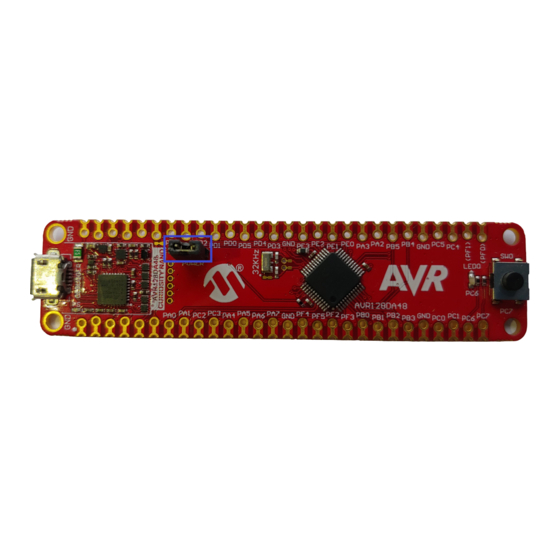
– AVR128DA48 Curiosity Nano Board (DM164151) with a small hardware modification described in this
document
– Power Debugger (ATPOWERDEBUGGER)
– Two Micro-USB cables: one for the Power Debugger and one for the Curiosity Nano Board
– Two small wires with holes on both ends for pins
•
Software Prerequisites
®
– MPLAB
X 5.40
– MCC plug-in for MPLAB X version 3.95
– AVR library for MCC version 2.3.0
– Atmel Studio newest version
Introduction
This document shows the differences in power consumption between a pure software approach and the use of CIPs
for accomplishing different tasks.
This hands-on training covers the following topics:
•
Assignment 1: Event System Compared to Interrupts
•
Assignment 2: Software Accumulation Compared to Hardware Accumulation for Analog-to-Digital Converter
(ADC)
Basic theory related to each assignment is introduced at the beginning of each assignment, the functionality is then
verified through the Atmel Studio Data Visualizer.
©
2020 Microchip Technology Inc.
AVR
®
DA Training Manual
Training Manual
DS40002243A-page 1
Advertisement
Table of Contents

Related Manuals for Microchip Technology AVR128DA48


Summary of Contents for Microchip Technology AVR128DA48
-
Page 1: Prerequisites
Low-Power Modes Using Curiosity Nano Prerequisites • Hardware Prerequisites – AVR128DA48 Curiosity Nano Board (DM164151) with a small hardware modification described in this document – Power Debugger (ATPOWERDEBUGGER) – Two Micro-USB cables: one for the Power Debugger and one for the Curiosity Nano Board –... -
Page 2: Icon Key Identifiers
To do: Highlights objectives to be completed. Result: Highlights the expected result of an assignment step. Indicates important information. WARNING Execute: Highlights actions to be executed out of the target when necessary. Training Manual DS40002243A-page 2 © 2020 Microchip Technology Inc. -
Page 3: Table Of Contents
Revision History............................ 46 The Microchip Website..........................47 Product Change Notification Service......................47 Customer Support............................47 Microchip Devices Code Protection Feature....................47 Legal Notice..............................48 Trademarks..............................48 Quality Management System........................49 Worldwide Sales and Service........................50 Training Manual DS40002243A-page 3 © 2020 Microchip Technology Inc. -
Page 4: Assignment 1: Event System Compared To Interrupts
Sleep to read the result. Hardware Description The Curiosity board is based on an AVR128DA48 microcontroller, a Nano embedded debugger, an LED, and a button. The Nano debugger allows the user to program the board and run debugging features without the need for external hardware. -
Page 5: Explaining The Modules Used
Creating the Software Implementation Program To do: Configure the hardware modules that will be used in this project and add code to the project. Create a new MPLAB X project for AVR128DA48. 1.1. Open MPLAB X. - Page 6 Assignment 1: Event System Compared to Int... Figure 1-4. Project Type 1.4. In the Device field, search for AVR128DA48. In the Tool category, select the Curiosity Nano board if it is connected to the computer, otherwise select None. Click Next. Figure 1-5. Device Selection 1.5.
- Page 7 Give a name to the project (and the location where to be saved) and click Finish. Figure 1-7. Project Name Open MPLAB Code Configurator (MCC) and configure the peripherals. 2.1. In System Module, choose the clock source as the internal oscillator with 24 MHz clock. Training Manual DS40002243A-page 7 © 2020 Microchip Technology Inc.
- Page 8 Info: Go to the Registers tab in System Module and scroll down to SLPCTRL. Modify the CTRLA register to enable Sleep and select the mode. Figure 1-9. Sleep Configuration 2.3. Add the VREF module from Device resources and configure it to provide 2.048V reference to the ADC. Training Manual DS40002243A-page 8 © 2020 Microchip Technology Inc.
- Page 9 Hardware Settings tab. The 12-bit mode is set by default. The RUNSTBY bit can be changed from the Registers tab and it is found in the CTRLA register. Training Manual DS40002243A-page 9 © 2020 Microchip Technology Inc.
- Page 10 1, and Run-In Standby (RUNSTBY) activated. Info: The clock, prescaling factor, and period are set from the Hardware Settings tab, while the RUNSTBY bit is found in the register pane in the CTRLA register. Training Manual DS40002243A-page 10 © 2020 Microchip Technology Inc.
- Page 11 Interrupt Settings tab of the ADC module, and the RTC interrupt is enabled from the Interrupt Settings tab of the RTC module (seen in the pictures for the previous steps). Training Manual DS40002243A-page 11 © 2020 Microchip Technology Inc.
- Page 12 3.1. Add the following code to the main.c file. #include <avr/io.h> #include <avr/sleep.h> #include "mcc_generated_files/mcc.h" void TIMER_interrupt(void); uint16_t result; main(void) SYSTEM_Initialize(); RTC_SetOVFIsrCallback(TIMER_interrupt); while (1){ sleep_cpu(); result = ADC0_GetConversionResult(); void TIMER_interrupt() ADC0_StartConversion(ADC_MUXPOS_TEMPSENSE_gc); Training Manual DS40002243A-page 12 © 2020 Microchip Technology Inc.
-
Page 13: Creating The Event System Implementation Project
Click to browse repositories Creating the Event System Implementation Project To do: Configure the hardware modules that will be used in this project and add code to the project. Create a new MPLAB X project for AVR128DA48. 1.1. Open MPLAB X. - Page 14 Click Next (the Microchip Embedded Stand-alone Project is selected by default). Figure 1-19. Project Type 1.4. In the Device field search for AVR128DA48. In the Tool category, select the Curiosity Nano board if it is connected to the computer, otherwise select None. Click Next. Training Manual DS40002243A-page 14 ©...
- Page 15 Assignment 1: Event System Compared to Int... Figure 1-20. Device Selection 1.5. Select XC8 2.20 compiler and click Next. Figure 1-21. Compiler Selection 1.6. Give a name to the project (and the location where to save) and click Finish. Training Manual DS40002243A-page 15 © 2020 Microchip Technology Inc.
- Page 16 Info: Choose the Clock source as Internal Oscillator, the Oscillator Frequency Options as the 24 MHz system clock, and disable the Prescaler. Figure 1-23. System Module Configuration 2.2. In the Registers tab of System Module, enable Sleep and set the mode to Standby. Training Manual DS40002243A-page 16 © 2020 Microchip Technology Inc.
- Page 17 Info: The ADC voltage reference must be configured to the internal 2.048V reference. Do not enable the Force ADC voltage option. Info: The VREF is used to enable the temperature sensor of the microcontroller. Figure 1-25. VREF Configuration Training Manual DS40002243A-page 17 © 2020 Microchip Technology Inc.
- Page 18 The RUNSTBY bit can be changed from the Registers tab and is found in the CTRLA register. The STARTEI bit is found in the EVCTRL register in the Registers tab. Figure 1-26. ADC Configuration Figure 1-27. RUNSTBY RTC Configuration Training Manual DS40002243A-page 18 © 2020 Microchip Technology Inc.
- Page 19 Info: The clock, prescaling factor and period are set from the Hardware Settings tab, while the RUNSTBY bit is found in the register pane in the CTRLA register. Disable the Overflow Interrupt if it is enabled. Figure 1-29. RTC Configuration Training Manual DS40002243A-page 19 © 2020 Microchip Technology Inc.
- Page 20 Add the EVSYS module. Configure channel 0 event generator to be RTC_OVF and the event that will be triggered ADC0START. Configure channel 1 event generator to be ADC0_RESRDY and the event that will be triggered EVSYSEVOUTC. Figure 1-31. EVSYS Configuration Training Manual DS40002243A-page 20 © 2020 Microchip Technology Inc.
- Page 21 Figure 1-33. Pin Manager: Grid View 2.8. In the Pin Module, enable the interrupt-on-change of the PC2 pin to sense both edges. Figure 1-34. Pin Module Configuration 2.9. Enable Global Interrupts from Interrupt Manager. Training Manual DS40002243A-page 21 © 2020 Microchip Technology Inc.
- Page 22 Add code to the project. 3.1. Add code to the main.c file: #include "mcc_generated_files/mcc.h" #include <avr/sleep.h> void GPIO_Interrupt(void); uint16_t volatile result; main(void) SYSTEM_Initialize(); ADC0.MUXPOS = ADC_MUXPOS_TEMPSENSE_gc; PORTC_PC2_SetInterruptHandler(GPIO_Interrupt); while (1){ sleep_cpu(); void GPIO_Interrupt(void) result = ADC0_GetConversionResult(); Training Manual DS40002243A-page 22 © 2020 Microchip Technology Inc.
-
Page 23: Programming The Device And Comparing Efficiency
With the software implementation program set as the main program, press the Make and Program Device button from the toolbar. A pop-up might appear that asks to select the tool that will be used as a programmer. Select the AVR128DA48 Curiosity Nano board. Figure 1-38. Make and Program the Device... - Page 24 Press Connect and a box labeled ‘power’ will appear. Select it and then press the wheel to open the menu. Disable the B channel. In case the Power field does not appear, disconnect the board and connect it again. WARNING Figure 1-41. Connect DGI Training Manual DS40002243A-page 24 © 2020 Microchip Technology Inc.
- Page 25 Go back to the Data Visualizer in Atmel Studio and in the DGI panel press Connect. Figure 1-45. Data Gateway Interface 2.5. Check the power box and edit the settings to disable the B channel. Training Manual DS40002243A-page 25 © 2020 Microchip Technology Inc.
- Page 26 Compare the two measurements. 3.1. Both power consumption graphs are open on the same screen. They can now be analyzed to observe the way the programs behaved. Figure 1-48. Software Implementation Compared to EVSYS Training Manual DS40002243A-page 26 © 2020 Microchip Technology Inc.
- Page 27 Interrupts implementation. As can be seen from the picture, the difference is fairly small of about 1.5 uA. This is due to the long amount of time the microcontroller spends in Sleep. Training Manual DS40002243A-page 27 © 2020 Microchip Technology Inc.
-
Page 28: Assignment 2: Software Accumulation Compared To Hardware Accumulation For Adc
ADC to run 128 conversions and add the results to the hardware accumulator. Creating the Software Implementation Project To do: Configure the hardware modules that will be used in this project and add code to the project. Create a new MPLAB X project for AVR128DA48. 1.1. Open MPLAB X. - Page 29 Assignment 2: Software Accumulation Compared ... Figure 2-2. Project Type 1.4. In the Device field search for: AVR128DA48. In the Tool category, select the Curiosity Nano board if it is connected to the computer, otherwise select None. Click Next. Figure 2-3. Device Selection 1.5.
- Page 30 Give a name to the project (and the location where to be saved) and click Finish. Figure 2-5. Project Name Open MPLAB Code Configurator (MCC) and configure the peripherals. 2.1. Configure the System Module to run on the internal oscillator at 24 MHz. Training Manual DS40002243A-page 30 © 2020 Microchip Technology Inc.
- Page 31 Info: The ADC voltage reference must be configured to the internal 2.048V reference. Do not enable the Force ADC Voltage option. Info: The VREF is used to enable the temperature sensor of the microcontroller. Training Manual DS40002243A-page 31 © 2020 Microchip Technology Inc.
- Page 32 Info: Right-shifted results option must be disabled. The sample length is selected in the Hardware Settings tab. The 12-bit mode is set by default. The same is with the no accumulation selection. Figure 2-8. ADC Configuration 2.4. Press the Generate button. Training Manual DS40002243A-page 32 © 2020 Microchip Technology Inc.
- Page 33 ADC0_GetConversionResult() returns the result of the last conversion • The for loop repeats the steps for starting a conversion, waiting for it to end and adding the result to the accumulator 128 times Training Manual DS40002243A-page 33 © 2020 Microchip Technology Inc.
-
Page 34: Creating The Hardware Implementation Project
Click to browse repositories Creating the Hardware Implementation Project To do: Configure the hardware modules that will be used in this project and add code to the project. Create a new MPLAB X project for AVR128DA48. 1.1. Open MPLAB X. - Page 35 Assignment 2: Software Accumulation Compared ... Figure 2-12. Project Type 1.4. In the Device field, search for: AVR128DA48. In the Tool category, select the Curiosity Nano board if it is connected to the computer, otherwise select None. Click Next. Figure 2-13. Device Selection 1.5.
- Page 36 Give a name to the project (and the location where to be saved) and click Finish. Figure 2-15. Project Name Open MPLAB Code Configurator (MCC) and configure the peripherals. 2.1. Configure the System Module to run on the internal oscillator at 24 MHz. Training Manual DS40002243A-page 36 © 2020 Microchip Technology Inc.
- Page 37 SLPCTRL. In the SLPCTRL.CTRLA register, modify the options to be enabled and Standby mode. Figure 2-17. Sleep Configuration 2.3. Add the VREF module from Device resources and configure it to provide 2.048V reference to the ADC. Training Manual DS40002243A-page 37 © 2020 Microchip Technology Inc.
- Page 38 Hardware Settings tab. The 12-bit mode is set by default. The RUNSTBY bit can be changed from the register view and is found in the CTRLA register. Training Manual DS40002243A-page 38 © 2020 Microchip Technology Inc.
- Page 39 DA Training Manual Assignment 2: Software Accumulation Compared ... Figure 2-19. ADC Configuration Figure 2-20. Run in Standby ADC Configuration 2.5. Enable the Result Ready Interrupt for the ADC and the Global Interrupts. Training Manual DS40002243A-page 39 © 2020 Microchip Technology Inc.
- Page 40 Add the following code to the main.c file: #include "mcc_generated_files/mcc.h" #include <avr/sleep.h> uint16_t result; main(void) SYSTEM_Initialize(); while (1){ ADC0_StartConversion(ADC_MUXPOS_TEMPSENSE_gc); sleep_cpu(); result = ADC0_GetConversionResult(); Info: SYSTEM_Initialize() is defined in mcc.c, ADC0_StartConversion(channel) and ADC0_GetConversionResult() are defined in adc0.c. Training Manual DS40002243A-page 40 © 2020 Microchip Technology Inc.
-
Page 41: Programming The Device And Comparing Power Efficiency
Make and Program Device button from the toolbar. A pop-up might appear that asks to select the tool that will be programmed. Select the AVR128DA48 Curiosity Nano board. Figure 2-24. Make and Program the Device 1.2. - Page 42 Press Connect and a box labeled ‘power’ will appear. Select it and then press the wheel to open the menu. Disable the B channel. In case the Power field does not appear, disconnect the board and connect it again. WARNING Figure 2-27. DGI Connect Training Manual DS40002243A-page 42 © 2020 Microchip Technology Inc.
- Page 43 Go back to the Data Visualizer in Atmel Studio and in the DGI panel press Connect. Figure 2-31. DGI Connect 2.5. Check the power box and edit the settings to disable the B channel. Training Manual DS40002243A-page 43 © 2020 Microchip Technology Inc.
- Page 44 Compare the two measurements. 3.1. Both power consumption graphs are open on the same screen. They can now be analyzed to observe the way the programs behaved. Figure 2-34. Software Accumulation Compared to Hardware Accumulation Training Manual DS40002243A-page 44 © 2020 Microchip Technology Inc.
- Page 45 Info: The top part displays the software accumulation, while the bottom part, the hardware accumulation. As can be seen from the picture, there is a 3.1 mA difference between the two, making the hardware implementation almost twice as efficient. Training Manual DS40002243A-page 45 © 2020 Microchip Technology Inc.
-
Page 46: Revision History
® DA Training Manual Revision History Revision History Revision Date Description 8/2020 Initial document release Training Manual DS40002243A-page 46 © 2020 Microchip Technology Inc. -
Page 47: The Microchip Website
Attempts to break Microchip’s code protection feature may be a violation of the Digital Millennium Copyright Act. If such acts allow unauthorized access to your software or other copyrighted work, you may have a right to sue for relief under that Act. Training Manual DS40002243A-page 47 © 2020 Microchip Technology Inc. -
Page 48: Legal Notice
The Adaptec logo, Frequency on Demand, Silicon Storage Technology, and Symmcom are registered trademarks of Microchip Technology Inc. in other countries. GestIC is a registered trademark of Microchip Technology Germany II GmbH & Co. KG, a subsidiary of Microchip Technology Inc., in other countries. -
Page 49: Quality Management System
® DA Training Manual Quality Management System For information regarding Microchip’s Quality Management Systems, please visit www.microchip.com/quality. Training Manual DS40002243A-page 49 © 2020 Microchip Technology Inc. -
Page 50: Worldwide Sales And Service
New York, NY Tel: 46-31-704-60-40 Tel: 631-435-6000 Sweden - Stockholm San Jose, CA Tel: 46-8-5090-4654 Tel: 408-735-9110 UK - Wokingham Tel: 408-436-4270 Tel: 44-118-921-5800 Canada - Toronto Fax: 44-118-921-5820 Tel: 905-695-1980 Fax: 905-695-2078 Training Manual DS40002243A-page 50 © 2020 Microchip Technology Inc.
Need help?
Do you have a question about the AVR128DA48 and is the answer not in the manual?
Questions and answers