
Subscribe to Our Youtube Channel
Related Manuals for ERA Invincible


Summary of Contents for ERA Invincible
- Page 1 SMART HOME SECURITY Dual Network Communicating Alarm System with RFID INVINCIBLE Instruction Manual Customer Helpline 0345 257 2500...
-
Page 2: Table Of Contents
Table of Contents Kit Contents --------------------------------------------------------------------- 01-02 Control Panel Layout ------------------------------------------------------------ 03-04 05-06 Getting Started ----------------------------------------------------------------- Power on -------------------------------------------------------------------------- Connect PSTN Landline --------------------------------------------------------- Insert a SIM Card ------------------------------------------------------------------- 07-08 Control Panel Operation --------------------------------------------------------- Access Control --------------------------------------------------------------------- Making Phone Calls ---------------------------------------------------------------- Voice Memo ----------------------------------------------------------------------- Function... - Page 3 Remote Phone Control ---------------------------------------------------------- 37-38 Answering Alarm Phone Call to Start Remote Control ----------------------------- Remote Control by Calling Landline Telephone Number -------------------------- Remote Control by Calling SIM Card Number ------------------------------------- SMS Operation------------------------------------------------------------------- 39-42 Disarm ----------------------------------------------------------------------------- Arm (Away Arm) ------------------------------------------------------------------ Part Arm (Home Mode) ----------------------------------------------------------- Monitor ---------------------------------------------------------------------------...
- Page 4 Telecommunications Terminal Equipment Directive, 1999/5/EC. Additional Accessories: This system can easily be extended at any time with the range of ERA Wireless Alarm Accessories, for details visit www.eraeverywhere.com or call our Customer Support team on 0345 257 2500 (local call rate).
- Page 5 FEATURES Wireless 433MHz frequency Built-in 1,000,000 RF codes combination maintains high reliability LCD Screen Touch Keypad with RFID Reader Guide menu on screen for ease of programming Supports up to 10 Remote Controls, 50 Wireless Sensors, and 50 RFID Contactless Tags Stores up to 6 alarm phone numbers 10 second voice memo and alarm voice message RFID Tag disarm.
-
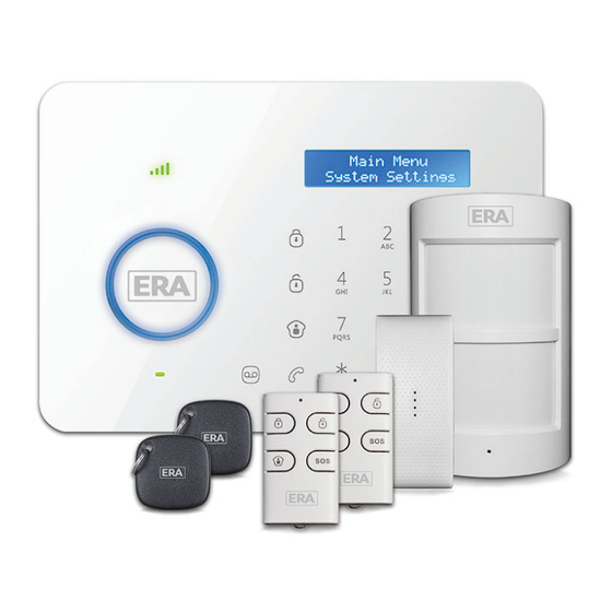
Page 6: Kit Contents
Kit Contents Control Panel The Dual Network Control Panel receives and processes signals from wireless Sensors and Remote Controls. Settings can easily be changed following the quick programming guide displayed on the LCD screen. When users pick up an alarm notification call they will hear the pre-recoded alarm voice message, from which they can choose to either monitor on-site or to disarm the system. - Page 7 Wireless Wireless Pet Friendly Door/Window Sensor x 1 Remote Control x 2 PIR Motion Sensor x 1 AC Adapter x 1 Telephone Cable x 1 RFID Tag x 2 Brackets (Wall-Mounted and Wall Bracket for PIR Screws and Wall Desktop) for Control Panel x 2 Motion Sensor x 1 Plugs x 4 Double-Sided Tape for...
-
Page 8: Control Panel Layout
Control Panel Layout Panel Front GSM Network LED Home Arm (Part Arm) RFID Tag Reader / Disarm Play Voice Memo LCD Display Escape Up/Down Enter Clear LED Indicator Call Voice Memo Button... - Page 9 Panel Back Microphone Tamper Switch Speaker Terminals for SIM Card Slot Wired Sensors AC Adapter Jack PSTN Landline Power Socket On/Off Backup Batteries Wired Siren Output (≤500mA) NC Input for Wired Sensor (Normal Zone) Output for Electronic Lock...
- Page 10 Panel Back Microphone Tamper Switch Speaker Terminals for SIM Card Slot Wired Sensors AC Adapter Jack PSTN Landline Power Socket On/Off Backup Batteries Wired Siren Output (≤500mA) NC Input for Wired Sensor (Normal Zone) Output for Electronic Lock...
-
Page 11: Getting Started
Getting Started Plug the AC Adapter output connector into the AC Adapter Jack in the Control Panel. Plug the AC adapter into a wall outlet. Switch the ON/OFF switch to ‘ON’ Note: The built-in rechargeable battery should be used only in the case of AC power failure. -
Page 12: Insert A Sim Card
Insert a SIM Card This step can be ignored if the GSM function is not required... 1. Switch off the Control Panel. 2. IMPORTANT: Remove the (default) code permanently from the SIM Card 3. Turn off the Voicemail function (if it is enabled) 4. -
Page 13: Control Panel Operation
Control Panel Operation Access Control The Control Panel’s RFID Reader enables quick system disarming by RFID Contactless Tag. RFID Tag disarming also unlocks an electronic door strike if fitted (not supplied). Pass the RFID Tag across the RFID Reader, the blue LED indicator will flash once and the system will disarm. -
Page 14: Voice Memo
Voice Memo To record a Voice Memo of up to 10 seconds press the [Record Voice Memo button for 3 seconds. The ‘Play Voice Memo’ circle will flash to indicate that a message has been recorded. To listen to a Voice Memo touch the center of the circle. The LED indicator will clear down once the voice memo has been played. -
Page 15: Alarm Functions
Alarm Functions 1. If GSM/GPRS functionality is enabled, when the system is disarmed by an RFID T ag, the Alarm will send an SMS/Push notification to the first stored Phone Number i.e. “TAG 01 Disarm” 2. The Alarm System Settings can be viewed via the E11 App or by sending an SMS “00"... -
Page 17: Door/Window Sensor
Door/Window Sensor The Door/Window Sensor comprises of a transmitter and a magnet. The Sensor can be mounted on doors, windows and any other object that can be opened or closed. When the transmitter and magnet are separated by more than 2 cm, the Sensor will send a signal to the Control Panel to trigger an alarm. - Page 21 Part-Arm (Home Mode) Send “2" to Part Arm the System. Sensors set to the home mode zone are in disarmed status; all other Sensors remain in armed status. That is, you can move freely around areas of your property where the Sensors are set to a ‘home mode’ zone; however, all Sensors set to a ‘normal zone’...
- Page 22 Installation Advice 1. Fit/position Sensor(s) so that the detection range covers primary entry/exit points 2. Adjust the Sensor Angle for maximum coverage The installation angle affects sensitivity directly. For optimal sensitivity the walk direction must be vertical to the infrared direction.
- Page 23 3. Avoid facing towards glass windows or doors Detection sensitivity can be affected by movement outside of a window/glass door, etc., that falls within the detection range, such as a flow of traffic (vehicles, people, etc). 4. Avoid facing or positioning close to a heat source This includes: heat extraction units, heaters, air conditioning units, microwave oven, refrigerator, freezer,...
-
Page 24: Lcd Display Contents
LCD Display Contents System Status Display Content Line Disconnect AC Power Failure Host Low Battery GPRS Connected Stand-by Sensor 1-50 (Sensor Name) Low Battery NO SIM CARD GPRS Connecting GPRS Disconnected No GPRS Signal System Arm System Disarm System Home Arm Remote Arm Remote Disarm Remote Home Arm... - Page 25 Disarm Arm or Disarm Home Arm Alarm Alarm Remote SOS Alarm Linecut Alarm Duress Alarm Alarm Alarm Panel Tamper Alarm Wired Sensor Sensor 01-50 (Sensor Name) Sensor Tamper Alarm Sensor 01-50 (Sensor Name) Sensor 01-50 (Sensor Name) Low Battery...
-
Page 26: Lcd Display Menu
LCD Display Menu Press any key on the touchpad to ‘awaken’ the LCD Display. Input the admin code (Default: 123456), and then press [Enter] to enter into the setting menu. Main Menu Sub Menu 2 Sub Menu 3 Sub Menu 1 Alarm Number1-6 Add Phone Number... -
Page 27: Settings
Date Date And Date Format Time Time Entry Delay <000S> Entry Exit Delay Exit Delay <000S> Backlight Time <20S> Auto Arm Time <00:00:00> Auto Arm/ Disarm Auto Disarm Time System <00:00:00> Settings Edit Welcome Linecut Alarm Keypad Tones Input 6 Digits Admin Code <Default Code 123456>... - Page 28 Ringing Times Alarm Message Record Siren On/Off <On/Off> Wired Siren Arm/Disarm Tone <On/Off> Siren On/Off <On/Off> Wireless Siren Arm/Disarm Tone <On/Off> Siren Setup Siren On/Off <Off/Low/High> Built-in Siren Arm/Disarm Tone <On/Off> System Settings Siren Alert Time <300S> Input 4 Digits User ID<1234>...
-
Page 29: Alarm Phone Number Setup
Settings Log into the Menu (press any key on the touchpad to ‘awaken’ the LCD Screen). Input the admin code (Default: 123456), and then press [Enter] to enter into the setting menu. Important: The default language of this alarm system is set to English, you can change language in the [Language]... -
Page 30: Add/Delete/Edit Accessories
2. Add/Delete/Edit Accessories The Control Panel will only receive a signal from an accessory once connected to the Control Panel. Add/Delete Remote Controls or Wireless Keypads Log into the menu, press , choose “Accessories”, press [Enter] Press , choose “Remote & Keypad”, press [Enter] Press , choose “Add”, press... - Page 31 Edit To rename an RFID Tag, choose “Edit Name” in step as above and press [Enter] then input the name. Note: In the event of incorrectly inputting the name press the button on the Control Panel to clear down and start again . Press the [ESC] to exit.
- Page 32 Normal Sensor: Arm Mode , when normal Sensors are triggered the system will alarm. In disarm mode, when normal Sensors are triggered, the system will not alarm. 24 Hour Sensor: When 24 hour Sensors are triggered, the system will alarm regardless of the alarm status.
-
Page 33: System Settings
3. System Settings Date and Time Date Log into the menu, press , choose “System Settings”, press [Enter] Press , choose “Date and Time”, press [Enter] Press , choose “Date”, press [Enter] Input date, press [Enter] Date Format Log into the menu, press , choose “System Settings”, press [Enter] Press... - Page 34 Input time for entry delay; press [Enter] for confirmation. Entry delay time is calculated on seconds; the default is 0 second (off ); the set-up range is 0-999 seconds. Note: For Sensors set to the 24-hour zone, a timed entry/exit delay cannot be set (refer to page 30) Exit Delay Exit Delay is set to leave time for user to exit the property before the system is armed.
- Page 35 Timed Disarm Log into the menu, press , choose “System Settings”, press [Enter] confirmation. Press , choose “Auto Arm/Disarm”, press [Enter] Press , choose “Auto Disarm Time”, press [Enter] Input exact time for disarming; press [Enter] Edit Greeting Message To display a greeting message on the LCD screen when the alarm is turned on or the touchpad is activated: Log into the menu, press , choose “System Settings”, press...
- Page 36 Access Code The Control Panel is supplied set to a default user code, admin code and duress code. Please change all codes before system use and only disclose your codes to authorised system users. Admin Code An ‘admin code’ user can arm and disarm the system, change system settings, reset codes etc.
- Page 37 Remote Phone Control Users can operate the system remotely. To adjust the number of rings after which Remote Phone Control operation will be activated: Log into the menu, press , choose “System Settings”, press [Enter] Press , choose “Ringing Times”, press [Enter] Input 5~9 for number of rings to be made, press [Enter]...
- Page 38 Turn On/Off Arm/Disarm Beep for Wired Siren Log into the menu, press , choose “System Settings”, press [Enter] Press , choose “Siren Setup”, press [Enter] Press , choose “Wired Siren”, press [Enter] Press , choose “Arm/Disarm Beep”, press [Enter] Press , choose “On”...
- Page 39 Built-in Siren The built-in siren is inside the Control Panel. Turn On/Off the built-in Control Panel Siren Log into the menu, press , choose “System Settings”, press [Enter] Press , choose “Siren Setup”, press [Enter] Press , choose “Built-in Siren”, press [Enter] Press , choose Siren On/Off, press...
- Page 40 User ID for CMS Please see details at Page 36: Connect to CMS Upload Arm Report Please see details at Page 37: Connect to CMS Upload Disarm Report Please see details at Page 37: Connect to CMS GPRS & Line Status Messages When GPRS and Live Status messages are set to ‘on’, the Control Panel will display a warning message in the event of the GPRS signal and landline connection being lost.
-
Page 41: Check Event Logs
Reset Log into the menu, press , choose “System Settings”, press [Enter] Press , choose “Reset”, press [Enter] to reset the system to default setting. Note: All system settings will be restored to the default factory setting but the paired Sensors will remain working. -
Page 42: Connect To Cms
Connect to CMS Please ignore this step if not connecting/contracting to a CMS centre. When connected to a CMS Centre, the Control Panel will upload the contact ID to the CMS centre automatically upon intrusion. Add CMS Telephone Number Log into the menu, choose “Phone Numbers”, press [Enter] Press , choose “Add Phone Number”, press... -
Page 43: Upload Arm/ Disarm Report To Cms Center
Upload Arm/ Disarm Report to CMS Centre When this function is enabled, all arm/disarm reports will be uploaded automatically to the CMS centre to notify of the alarm system status. After the User ID is set, press to choose “Arm Upload” or “Disarm Upload”, press [Enter] Press... -
Page 44: Sms Operation
SMS Operation The system can be controlled by sending SMS commands to the SIM card number of the Control Panel. SMS messages are charged in accordance with your network service provider. Note: It is important to store the user telephone number(s) during system set-up in order to prevent unauthorised control by any other telephone number. -
Page 45: Part Arm (Home Mode)
Part-Arm (Home Mode) Send “2" to Part Arm the System. Sensors set to the home mode zone are in disarmed status; all other Sensors remain in armed status. That is, you can move freely around areas of your property where the Sensors are set to a ‘home mode’ zone; however, all Sensors set to a ‘normal zone’... -
Page 46: System Enquiry
System Enquiry Send "18" to the SIM card in the Control Panel to check the setting status of the system. Turn off arm/disarm message notice Send “20" to switch off the Arm/ Disarm text notification. Note: Disarm by RFID text messages will still be received if already setup. Note: The system default is set to turn off the arm/disarm message notice. -
Page 47: App Operation
If selecting SMS: for iPhone, the SMS sending interface will be displayed. For Android smartphones the SMS will be sent directly to the phone number of the Control Panel without interface redirection. Download and Install the FREE APP Search keywords “ERA Invincible Alarm” in Apple Store or Google Play. ① ② ③... -
Page 48: Control Through Sms
Control through SMS Any telephone number can operate the system through APP by default. We recommend you store your alarm phone numbers on the Control Panel when setting up the system so that only the commands from these numbers are recognised. 1. - Page 49 2. Main Menu Functions Enter the telephone number of the Control Panel to enter the main menu. Once entered you can disarm, arm, home arm, check system settings, monitor the alarm status and leave a voice memo. 3. Delete Accounts iPhone: [EDIT] , choose the account number, tap...
-
Page 50: Control Through Gprs Data
Control through GPRS Data APN Setting The Access Point Name (APN) is the name for settings your phone reads to set up a connection to the gateway between your carrier’s cellular network and the public internet. If the SIM card of the Control Panel doesn’t work, then some setting changes will be required to enable the APN to open the GPRS function: Send 'APN' to the Control Panel SIM Card;... - Page 51 1. Register Registering an account enables you to link the alarm system to your smartphone. Enter login interface ① Tap E11 APP , choose [GPRS] , and then the login interface appears. Register an account ② [Register] , input your mobile number, password and code (Serial No) and device ID (as shown on the label on the back of the Control Panel), and then tap [OK] Note:...
- Page 52 2. Operation on Main Menu Main menu functions: Disarm, Arm, Part Arm, Monitor, leave Voice Memo. ① ② ④ ③ ⑤ ⑥ ⑦ ⑨ ⑧ Press on the main menu after login, tap [OK] on the dialog box to confirm ①...
-
Page 53: Pet Friendly Pir Motion Sensor
Pet Friendly PIR Motion Sensor We recommend to mount the Sensor at the height of 2-2.2m from the ground. (For installation notices, please see page 16-17) 2-2.2m Ground Fix the installation bracket on the wall with screws, and then fit the groove at the back of the Sensor on the bracket. -
Page 54: Testing
Testing Press the test button at the back of the PIR Sensor, walk from left to right within the detection scope to check that the Sensor is working. The LED indicator light will light up when movement is detected. When in Test Mode, the Sensor will search for movement every 10 seconds. -
Page 55: Faq
Cause Troubleshooting Issue Open battery compartment, Power switch is off turn on the power No response from Contact your retailer Control panel AC Power failure operation Lithium battery backup Connect to mains power with power exhausted adapter Make sure the Panel is Control Panel not in Learn Mode set to Learn Mode Make sure the triggered... -
Page 56: Specifications
Specifications Control Panel Power Supply Input DC 12V 500mA, 6Wh Standby Current < 90mA Alarm Current < 300mA Backup Battery BL-5B 3.7V 800mAh rechargeable lithium battery x 2 pcs Internal Siren Volume 95dB Radio Frequency 433MHz 6 alarm phone numbers and 2 CMS numbers Maximum Stored Phone No. - Page 57 Wireless Door/Window Sensor Power Supply DC 3V (CR2032 Lithium Battery x 2 pc) Static Current < 5uA Alarm Current < 9mA < 80m (in open area) Transmitting Distance 433MHz Radio Frequency ABS plastic Housing Material Temperature 0°C ~+ 55°C Operating temperature Relative Humidity <...
-
Page 58: Available Accessories
Available Accessories: ERA Wireless Accessories can be added at any time and include: Pet Friendly PIR Motion Sensor (EPIR) Magnetic Door/Window Sensor (EMAG) Remote Control (EREM) WIFI HD IP Camera (IP116) Ceiling Mounted PIR Sensor (P700) Narrow Beam PIR Sensor (P800) - Page 59 PRODUCT GUARANTEE * We at ERA firmly believe in the quality of our goods. Our technology achieves outstanding performance and durability and we can therefore offer, in addition to your statutory rights, an additional limited guarantee. In the event of any material defects in any product manufactured by...
- Page 60 Notes:...
- Page 61 Notes:...
- Page 62 Customer Helpline 0345 257 2500 www.eraeverywhere.com ERA Home Security Valiant Way, Wolverhampton, West Midlands WV9 5GB Email: alarms@eraeverywhere.com...
Need help?
Do you have a question about the Invincible and is the answer not in the manual?
Questions and answers