Table of Contents
Advertisement
Quick Links
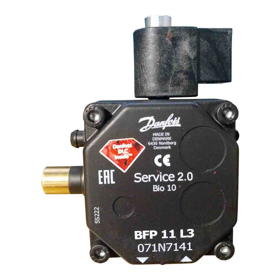
BFP 11 L3
Fig. 1
DANSK
ENGLISH
Symbol-
Symbols
forklaring
Trykregu-
Pressure
P
lering
regulation
1
Sugeledning
Suction line
S
G
/
G
/
1
1
4
4
Returledning
Return line
R
G
1
/
G
1
/
4
4
Dysetilslut-
Nozzle conn.
ning G
/
G
/
1
1
8
8
Patron-
Cartridge
F
filter
filter
Tilslutning
Vacuum
for vacuum-
meter conn.
meter G
/
G
/
1
1
8
8
Tilslutning
Pressure
for mano-
gauge conn.
meter G
/
G
/
1
1
8
8
Fig. 5
Fig. 8
DK 1-strengs system: skrue med skive
GB 1-pipe operation: screw with washer
D
Einstrangsystem: Schraube mit
Scheibe
F
Installation à un tuyau: vis avec
rondelle
E
Para operar en instalaciones de
1 tubería: tornillo con arandela
I
Funzionamento monotubo: vite con
rondella
S
1-rörsanläggning: skruv med skiva
NL 1-pijpssysteem: schroef met schijf
SF 1-putkikäyttö: ruuvi levyllä
INSTRUCTIONS
BFP Service pump
BFP 11 R3
Fig. 2
DEUTSCH
FRANCAIS
Symbol-
Légende des
erklärung
symboles
Druck-
Réglage de
regelung
pression
Conduite
Saugleitung
d'aspirat.
G
/
1
4
G
/
1
4
Rücklauf-
Conduite de
leitung
retour G
G
1
/
4
Düsenan-
Raccordement
schluss G
/
gicleur G
1
8
Patronen-
Cartouche
filter
filtrante
Anschluss für
Raccordement
Vakuum-
vacuomètre
meter G
/
G
/
1
1
8
8
Anschluss für
Raccordement
Manometer
manomètre
G
/
G
/
1
1
8
8
BFP 11
DK 2-strengs system: skrue uden skive
GB 2-pipe operation: screw without washer
D
Zweistrangsystem: Schraube ohne
Scheibe
F
Installation à deux tuyaux: vis sans
rondelle
E
Para operar en instalaciones de
2 tuberías: tornillo sin arandela
I
Funzionamento a 2 tubi: vite senza
rondella
S
2-rörsanläggning: skruv utan skiva
NL 2-pijpssysteem: schroef zonder schijf
SF 2-putkikäyttö: ruuvi ilman levyä
BFP 20/21
Fig. 3
ESPAÑOL
ITALIANO
Legenda
Símbolos
simboli
Regulación
Regolazione
de presión
pressione
Tubería de
Tubazione di
aspiración
aspirazione
G
/
G
/
1
1
4
4
Tubería de
Tubazione di
retorno
ritorno
1
/
4
G
1
/
G
1
/
4
4
Conexión
Attacco linea
izquierda de la ugello a
/
1
8
boquilla G
/
sinistra G
1
8
Filtro de
Filtro a
cartucho
cartuccia
Conexión de
Attacco
medidor de
vuotometro
vacio G
/
1
8
G
/
1
8
Conexión de
Attacco
manómetro
manometro
G
/
G
/
1
1
8
8
Fig. 6
Fig. 9
DK 1-strengs system: uden skrue
GB 1-pipe operation: without screw
D
Einstrangsystem: ohne Schraube
F
Installation à un tuyau: pas de vis
E
Para operar en instalaciones de
1 tubería: Sin el tornillo
I
Funzionamento monotubo:
senza vite
S
1-rörsanläggning: utan skruv
NL 1-pijpssysteem: zonder schroef
SF 1-putkikäyttö: ruuvi pois
BFP 41
Fig. 4
SVENSKA
NEDERLANDS
Symbol-
Symbolen
förklaring
Tryck-
Drukregelaar
reglering
Sugledning
Zuigleiding
G
/
G
/
1
1
4
4
Returledning
Retourleiding
G
1
/
G
1
/
4
4
Munstyck-
Nozzle-
anslutning
aansluiting
/
G
/
G
/
1
1
1
8
8
8
Patron-
Filter-
filter
patroon
Vacuüm-
Anslutning
meter-
för vakuum-
aansluiting G
meter
G
/
1
8
Anslutning
Manometer-
för mano-
aansluiting
meter
G
/
G
/
1
1
8
8
Fig. 7
BFP 20/21/41
DK 2-strengs system: isat skrue
GB 2-pipe operation: screw fitted
D
Zweistrangsystem: eingesetzte
Schraube
F
Installation à deux tuyaux: vis
E
Para operar en instalaciones de
2 tuberías: con el tornillo
I
Funzionamento a 2 tubi:
avvitare la vite
S
2-rörsanläggning: med skruv
NL 2-pijpssysteem: met schroef
SF 2-putkikäyttö: ruuvi paikalla
520F0084 DKBD.PI.010.H8.62 11-2006
SUOMEKSI
Merkkien
selitykset
Paineen-
säätö
Imuliitäntä
G
/
1
4
Paluuliitäntä
G
1
/
4
Suutinliitäntä
G
/
1
8
Patruuna-
suodatin
Alipainemit-
tarin liitäntä
/
G
/
1
1
8
8
Painemittari-
liitäntä
G
/
1
8
Advertisement
Table of Contents

Related Manuals for Danfoss BFP 11 L3


Summary of Contents for Danfoss BFP 11 L3
- Page 1 INSTRUCTIONS BFP Service pump BFP 11 L3 BFP 11 R3 BFP 20/21 BFP 41 Fig. 1 Fig. 2 Fig. 3 Fig. 4 DANSK ENGLISH DEUTSCH FRANCAIS ESPAÑOL ITALIANO SVENSKA NEDERLANDS SUOMEKSI Symbol- Symbol- Légende des Legenda Symbol- Merkkien Symbols Símbolos Symbolen forklaring erklärung...
- Page 2 Fig. 10 BFP type 3 BFP type 5 Fig. 11 Fig. 12 DELTA DELTA ECKERLE ECKERLE SUNTEC MS 071G 1-PIPE 2-PIPE Konverteringstabel BFP 071N BFP 071N ) VIRL. 3+4 ) VDIRL. 3+4 UNI 1.1R5R14 ) UNI 2.1R1(R+S)14 AN 47A73 MS 10 R30123 BFP 20 R30169 Conversion table VIRR. 3+4 VDIRR. 3+4 1.1R5L14 2.1R1(L+M)14 47B73 R30123 R30169 D Konvertierungstabelle VILR. 3+4 VDILR. 3+4 1.1L5L14...
- Page 3 Fyringsgasolie 6 mm ∅4 ∅5 ∅6 ∅4 ∅5 ∅6 ∅5 ∅6 ∅8 Fuel gas oil 6 mm Heizöl 6 mm Fioul 6 mm Combustible líquido 6 mm Gasolio 6 mm Eldningsolja 6 mm /s Huisbrandolie 6 mm /s Polttoöljy 6 mm DK Dysekapacitet = 0 kPa GB Nozzle capacity D Düsenleistung F Débit au gicleur E Capacidad de la boquilla 2,5 kg/h 5 kg/h 10 kg/h Portata all’ugello S Munstyckskapacitet...
- Page 4 Sugeledningerslængder i meter This applies to: DANSK Tabellerne gælder for en standard fyringsgasolie (Heizöl- • Direction of rotation EL) af normal handelskvalitet iht. gældende normer. R: Right Oliepumpe type BFP Ved igangsætning af et anlæg med tomt rørsystem bør L: Left oliepumpen ikke køre uden olie i mere end 5 minutter. • Location of nozzle port Tekniske data • Connections Viskositetsområde: 1,8-12 mm /s (cSt) • Location of side regulation Omdrejningstal: type 5 1400-3600 min Nozzle capacity type 3 2400-3600 min ENGLISH Fig. 11 and 12 show the pump nozzle capacities. Trykområde: The pumps are factory set at 10 bar ±1 bar. Oil pump type BFP BFP 11: 7-15 bar Suction line lengths in metres...
- Page 5 Filterwechsel mit Ringilter, BFP 11: • la pompe BFP 41 se purge par la vis P sur le devant (fig. Nota: Die vier Schrauben des Deckels entfernen und ein neues 6.) et avec électrovanne fermée. • Todas las BFP 20/21 tienen una conexión para boquilla Filter montieren. • Si un díspositif hydraulique est utilisé pour le volet opcional. d’air, il ne doit pas être branché sur l’une ou l’autre • Todas las BFP 20/21 se suministran con un tapón Aufbau des Typensystems: sortie de gicleur (BFP 20/21), mais il doit être branché metálico en la conexión derecha para boquilla. BFP X X X X sur la sortie frontale P. • Todas las bombas BFP 20/21/41 para instalaciones de 1 tubería se suministran con un tornillo de conversión 3 Leistung 240 kW Modification pour passer d’une installation mono- para funcionamiento en 2-tuberías.
- Page 6 Ció vale per: BFP X X X X ITALIANO • Senso di rotazione dell’albero R: Destro 3 Kapacitet 240 kW Pompa per gasolio tipo BFP L: Sinisto 5 Kapacitet 400 kW • Posizionamento valvola Caratteristiche tecniche • Connessioni R Rotationsriktning höger Campo di viscosità: 1,8-12 mm /s (cSt) • Posizionamento del distritivo di regolazione L Rotationsriktning vänster Velocità di rotazione: tipo 5 1400-3600 min -1 tipo 3 2400-3600 min -1 Portata 0 Utan magnetventil Campo di pressione: Le fig. 11 e 12 mostrano la portata della pompa all’ugello.
- Page 7 • De BFP 41 wordt via de P-poort aan de voorzijde (afb. Huomaa! 6) en met een gesloten magneetventiel ontlucht. • BFP 20/21 pumpuissa on vaihtoehtoinen suutinyhde. • Als er een hydraulische cilinder b.b.v. de luchtregelklep • Kaikissa BFP 20/21 pumpuissa on metallinen tulppa gebruikt wordt, mag deze niet op een alternatieve oikeanpuoleisessa suutinyhteessä. Tätä suutinyhdettä verstuiverpoort (BFP 20/21) aangesloten worden, maar käytettäessä metallinen tulppa asennetaan vasem- moet in plaats hiervan op de P-poort op de voorzijde manpuoleiseen suutinyhteeseen. worden aangesloten. • Kaikkien BFP 20/21/41 1-putkikäyttöisten pumppujen mukana toimitetaan muovipussi, joka sisältää sulku- Omschakelen van 1- naar 2-pijpssysteem ruuvin 2-putkikäyttöä varten. (afb. 8 en 9) • BFP 11 pumpussa, joka toimitetaan vain 1-putkikäytöl- le, on vain 1 suutinyhde: BFP 11L3 pumpussa suutiny- Vervangen van het filterpatroon BFP 20/21 en 41 hde on vasemmalla puolella ja BFP 11R3 pumpussa (afb.
- Page 8 Produced by Danfoss Industri Service - G1 advertising 06.11 FO-Bi.