Table of Contents
Advertisement
Quick Links
Advertisement
Table of Contents

Subscribe to Our Youtube Channel
Related Manuals for Koden MDC-2000BB Series


Summary of Contents for Koden MDC-2000BB Series
- Page 4 - This page intentionally left blank.-...
-
Page 5: Document Revision History
No part of this publication may be reproduced, transmitted, translated in any from by any means without the written permission of Koden Electronics Co., Ltd. The technical descriptions contained in this publication are subject to change without notice. Koden assumes no responsibility for any errors, incidentals or consequential damages caused by misinterpretation of the descriptions contained in this publication. -
Page 6: Important Notices
Important Notices MDC-2000BB Series Important Notices The re-use and transcription of Operation Manual (hereafter called this manual) needs permission of our company. Our company prohibits the un-authorized re-use and transcription. If this manual is lost or damaged, consult our dealer or our company. -
Page 7: For Your Safe Operation
MDC-2000BB Series For Your Safe Operation For Your Safe Operation Symbol used in this Operation Manual This manual uses the following symbols. Understand the meaning of each symbol and implement the maintenance and inspection. Symbol Meaning Mark for warning This symbol denotes that there is a risk of death or serious injury when not dealing with it correctly. - Page 8 For Your Safe Operation MDC-2000BB Series Caution Item on Equipment Caution on a high voltage inside. A high voltage, which may risk your life, is used. This high voltage remains in the circuit after you have powered off switch. To prevent...
- Page 9 MDC-2000BB Series For Your Safe Operation Caution Item on Handling Caution on the rotating aerial The radar antenna may start to rotate without notice. Please stand clear from the antenna for your safety. ENGLISH Caution on electromagnetic disturbance operating Antenna &...
- Page 10 For Your Safe Operation MDC-2000BB Series FRENCH Mise en garde relative aux perturbations électromagnétiques produites par les radars de navire L'antenne & l’émetteur des radars de navire ont un rayonnement d’ondes électromagnétique de haute intensité. Ceci peut causer des effets nocifs pour le corps humain en raison de son rayonnement continu.
- Page 11 MDC-2000BB Series For Your Safe Operation Warning Statements related to FCC and IC rules IC RSS-GEN, Sec 8.3 Warning Statement- (Required for Transmitters w/ detachable antennas) ENGLISH: This radio transmitter (identify the device by certification number, or model number if...
- Page 12 For Your Safe Operation MDC-2000BB Series IC RSS-102, Sec 2.6 Warning Statement Requirements ENGLISH: The applicant is responsible for providing proper instructions to the user of the radio device, and any usage restrictions, including limits of exposure durations. The user manual shall provide installation and operation instructions, as well as any special usage conditions, to ensure compliance with SAR and/or RF field strength limits.
- Page 13 MDC-2000BB Series For Your Safe Operation Warning statement regarding RF exposure compliance ENGLISH: The user manual of devices intended for controlled use shall also include information relating to the operating characteristics of the device; the operating instructions to ensure compliance with SAR and/or RF field strength limits;...
- Page 14 For Your Safe Operation MDC-2000BB Series will not occur in a particular installation. If this equipment does cause harmful interference to radio or television reception, which can be determined by turning the equipment off and on, the user is encouraged to try to correct the interference by one or more of the following measures: - Reorient or relocate the receiving antenna.
- Page 15 MDC-2000BB Series For Your Safe Operation Do not disassemble or modify. It may lead to trouble, fire, smoking or electric shock. In case of trouble, contact our dealer or our company. In case of smoke or fire, switch off the power in the boat and the power of equipment.
-
Page 16: Break In Procedure Of Stored Radar
Break in procedure of stored radar MDC-2000BB Series Break in procedure of stored radar Following procedure is recommended for “Break In” of the stored radar. Otherwise the radar sometimes exhibits unstable transmitting operation such as arcing at its initial operation after long period of storage and make the operation more difficult. -
Page 17: Table Of Contents
MDC-2000BB Series Contents Contents Document Revision History ....... i 1.12 EBL .......... 1-10 Important Notices ........ii 1.13 VRM ......... 1-10 For Your Safe Operation ......iii 1.14 Use of Function keys ....1-11 Break in procedure of stored radar ..xii How to use [F1] - [F6] keys .. -
Page 18: Contents
Number of Acquisition ....2-11 Signal Select ......3-6 Information Display ....2-11 NMEA ......... 3-6 ATA Performance ..... 2-11 Connection with the KODEN GPS Types and Meanings of ATA compass ........3-7 Symbols ........2-12 Preset ......... 3-7 Nav Display select ...... 3-7 Chapter 3 How to use the system Language Select ...... - Page 19 MDC-2000BB Series Contents Antenna ........3-7 unit ........... 5-29 Panel Test ........3-7 Pin Assignment of Rear LCD Test ........3-8 Connector ........ 5-30 Operation Hours Reset ....3-8 Connection of DC power TX Hours Reset ......3-8 cable ........5-31 ALL Reset ........
-
Page 20: Introduction
Introduction MDC-2000BB Series Introduction Thank for your purchase of KODEN marine radar MDC-2000BB Series. The quality and endurance of a unit is well considered. For the best performance, read this Operation Manual and operate a unit correctly and safely. The main features of this unit are as follows. -
Page 21: System Configuration
MDC-2000BB Series System Configuration System Configuration Connection Diagram Antenna-Scanner unit RB804/RB805/RB806/RB807/RB808/RB717A/RB718A MRO-112 MRM-112 Operation unit Processor unit External Buzzer KGC-222 or AIS Receiver Navigation equipment CCD camera Slave Display MRM-112 etc. Display Power 10.8 to 31.2VDC Legend Standard configuration Option... -
Page 22: Configuration Of Equipment
Configuration of Equipment MDC-2000BB Series Configuration of Equipment Standard Equipment Configuration List Weight/ Name of item Type Remarks Quantity Length Processor unit MRM-112 5.1 kg Operation unit With connecting MRO-112 0.94 kg cable (CW-601-5M) DC power cable 3-pin water resistant connector... - Page 23 MDC-2000BB Series Configuration of Equipment Types of Antenna-scanner unit Transmitting Type Shape Remarks Weight/Length Power RB804 Radome Interconnecting 8.3kg / 1.2ft cable, 10m*, 242J158055A-10M RB805 Radome Interconnecting 10kg / 2ft cable, 10m*, 242J158055A-10M RB806 with RW701A-03/04 Open Interconnecting 21kg / 3ft...
- Page 24 Configuration of Equipment MDC-2000BB Series Transmitting Type Shape Remarks Weight/Length Power RB717A with RW701A-04/06 Open Interconnecting 23kg / 4ft cable, 15m*, 242J159098B-15M 25kg / 6ft RB718A with RW701A-04/06 12kW Open Interconnecting 23kg / 4ft cable, 15m*, 242J159098B-15M 25kg / 6ft * Cables of 15m, 20m and 30m are available.
- Page 25 - This page intentionally left blank.-...
-
Page 26: Chapter 1 Basic Operation
Chapter 1 Basic Operation MDC-2000BB Series Chapter 1 Basic Operation The basic operation of this unit is as follows. For detailed explanation, refer to each item in this manual. Press the [ ] to turn on the power. 1.3 Power On/Off When [ST'BY] appears, press the [STBY/TX] key to start the transmission. - Page 27 MDC-2000BB Series Chapter 1 Basic Operation 0093120012-01...
-
Page 28: How To Read The Radar Screen
Chapter 1 Basic Operation MDC-2000BB Series How to read the radar screen Process Interference Rejection Enhance Off center Range Fixed marker interval Alarm Pulse width Display mode Heading line Trail Heading Ship speed cursor G:GAIN bar (0-100) Cursor position OWN ship's position... -
Page 29: How To Use The Keys
MDC-2000BB Series Chapter 1 Basic Operation How to use the keys (10) (11) (12) (16) (15) (14) (13) Various adjustment items can be set by operating each key. The menu is displayed by pressing the [MENU] key, and closes when pressing the [MENU] key again. - Page 30 Chapter 1 Basic Operation MDC-2000BB Series Number Key name Explanation Push: Turns on the power. Continuously pressing: Turns on or off the power. [STBY/TX] Starts or stops the transmission. [BRILL] Adjusts the brilliance and the brightness of the panel. [STC/FTC] Rotate: Changes the STC or FTC.
-
Page 31: Power On/Off
MDC-2000BB Series Chapter 1 Basic Operation Power On/Off Brilliance Adjustment Brightness Adjustment of Display Power On The brilliance of menu can be adjusted to make it Press the [ ] key to turn on the power. easier to see. The start-up menu is displayed. During the... -
Page 32: Switch-Over Of Range
Chapter 1 Basic Operation MDC-2000BB Series Switch-over of Range Result Picture after adjustment by GAIN : Land The observation range can be changed. Own ship Change of Range Press the [- RANGE +] key. When pressing the [+] key, an image shrinks but the observation range expands. -
Page 33: Stc Adjustment
MDC-2000BB Series Chapter 1 Basic Operation Picture after adjustment by STC: STC Adjustment Land In the short distance menu, even if waves are low and the sea surface is calm, an echo reflected from the sea surface appears in the Own ship image. -
Page 34: Ftc Adjustment
Chapter 1 Basic Operation MDC-2000BB Series FTC Adjustment When raining or snowing, due to reflection from rain or snow, an object is hard to be seen. By increasing the set value of FTC, the contour of an object, which was concealed by an image of rain or snow, appears. -
Page 35: 1.10 Setting Of Off Center
MDC-2000BB Series Chapter 1 Basic Operation 1.10 Setting of OFF CENTER 1.12 EBL When viewing widely in the heading, use this This mode is used when measuring the bearing function. from own ship to a target. Setup: OFF, ON (Initial value: OFF) -
Page 36: 1.14 Use Of Function Keys
Chapter 1 Basic Operation MDC-2000BB Series Select the number of the desired capture 1.14 Use of Function keys to be released with [ ] / [ ] keys and press the [ENT] key to set it. The following functions can be assigned to the In case of selecting [CURSOR] in the [F1] - [F6] keys. -
Page 37: Measuring The Distance And Bearing Between Two Points
MDC-2000BB Series Chapter 1 Basic Operation 1.17 Camera Display The video of the CCD camera can be displayed on the radar screen. (CCD camera: Prepared by a customer) cursor How to connect the CCD camera Connect CW-405-0.3M cable (optional cursor position cable) to the J6 in the rear connectors. -
Page 38: Chapter 2 How To Use The Menu
Chapter 2 How to use the menu MDC-2000BB Series Chapter 2 How to use the menu Select an item you desire to change with the How to operate the menu [ ] and [ ] keys. Display/Non-display of Menu ECHO... -
Page 39: H Up (Head Up)
MDC-2000BB Series Chapter 2 How to use the menu Change the setting of [MODE] with the [ ] NORTH and [ ] keys. Press the [MENU] key to close the menu. Four bearing displays of [H UP], [N UP], [C UP] Target 1 and [WPT UP] are provided. -
Page 40: Wpt Up (Waypoint Up)
Chapter 2 How to use the menu MDC-2000BB Series WPT UP (Waypoint Up) Own ship The WPT is the display mode to always orient the WPT to the top of the screen. When this mode is used in combination with the course up function of the plotter, the understandable image is available. -
Page 41: True Motion Reset
MDC-2000BB Series Chapter 2 How to use the menu DISPLAY SELECT OWN ship's position relocatable area in TM PPI / PPI PPI / NAV Press the [MENU] key to close the menu. Center of display PPI Display The radar screen is displayed on the entire display. -
Page 42: Note On Ppi/Ppi Display
Chapter 2 How to use the menu MDC-2000BB Series Note on PPI/PPI Display GAIN PRI.) Press the [MENU] key. In the PPI/PPI display, to avoid risk, the following functions do not work. Select [ECHO] → [PULSE]. ● TM (True Motion) Change the setting of [PULSE] with the [ ] ●... -
Page 43: True Display (T)
MDC-2000BB Series Chapter 2 How to use the menu The relative speed of a target with respect to own < MODE [ N UP ] > ship is drawn as a trail. Since the ship 2 is NORTH moving in the opposite direction at the identical speed, the speed derived by adding the ship 2 speed and own ship speed is drawn as a trail. -
Page 44: Cursor Shape
Chapter 2 How to use the menu MDC-2000BB Series Change the setting of [COLOR] with the [ ] SIDES], press the [ ] key. Then, the parallel and [ ] keys. cursor can be operated. The distance When selecting [DAY], the color of the entire... -
Page 45: 2.12 Alarm
MDC-2000BB Series Chapter 2 How to use the menu [DETECT COUNT] value. 2.12 Alarm [OUT Mode]: The alarm works when targets leave continuously from alarm area more than This mode is used when monitoring targets. [DETECT COUNT] value. When targets enter in the set range or exit from the set range, the buzzer notifies. -
Page 46: 2.14 Ais
Chapter 2 How to use the menu MDC-2000BB Series Normal Symbol Meanings 2.14 AIS Sleep Display* Displays ships of which information By installing the optional AIS interface board, the display is not performed. information on other ships, which are received by... -
Page 47: 2.15 Ata
MDC-2000BB Series Chapter 2 How to use the menu Automatic Acquisition 2.15 ATA Targets entering in the preset range can be To use the ATA, install the optional ATA board. automatically acquired. The ATA automatically tracks targets and stores Press the [MENU] key. -
Page 48: Target Level
Chapter 2 How to use the menu MDC-2000BB Series Target Level Select [ATA] → [MAN ACQ NUM]. Change the setting of [MAN ACQ NUM] with The signal level of a target to be the [ ] and [ ] keys. -
Page 49: Types And Meanings Of Ata
MDC-2000BB Series Chapter 2 How to use the menu Types and Meanings of ATA Symbols In the ATA, the symbols are displayed, overlaying on acquire-started targets. Normal Symbol Meanings Displayed when setting the acquisition. Displayed when in the stable tracking state. -
Page 50: Chapter 3 How To Use The System Menu
Chapter 3 How to use the system menu MDC-2000BB Series Chapter 3 How to use the system menu Display of System Menu Setting of Assist Items There is a standard menu which is displayed for In the supplement items of the system menu, to... -
Page 51: Wpt Display
MDC-2000BB Series Chapter 3 How to use the system menu WPT Display N UP/S UP Select ON or OFF of the WPT icon (flag mark) to Change the mode of the N UP or S UP of the be displayed on the radar screen. -
Page 52: Bearing Setting
Chapter 3 How to use the system menu MDC-2000BB Series displayed on the screen. Bearing Setting Adjust the bearing of the radar image on the screen. Setup: -180.0 to +180.0 (Initial value: 0.0) Press the [STBY/TX] key to start the transmission. -
Page 53: Stc Curve
MDC-2000BB Series Chapter 3 How to use the system menu range that can display the entire sea surface reflected echo can be displayed. Adjust the [STC/FTC] knob and stop it just before the sea surface reflected echo completely disappears (In the state that the sea surface reflected echo is sparsely displayed.) As shown in [Proper] below,... -
Page 54: Tune Select
Chapter 3 How to use the system menu MDC-2000BB Series The STC curve set value is applied to all Manual Tune Adjustment ranges. Due to a sudden environment change, the Note: The setting of STC characteristics automatic tuning may be detuned. In this case, needs to be performed in the ocean. -
Page 55: Interference Rejection
MDC-2000BB Series Chapter 3 How to use the system menu Change the setting of [Pulse Width Press the [MENU] key. Adjustment] with the [ ] and [ ] keys. Move to the system menu. Refer to 3.1 Display of System Menu. -
Page 56: Connection With The Koden Gps Compass
For the NMEA sentence, refer to 5.6 Echo Color Set List of Input/Output sentence. Set an arbitrary color to the video color. Connection with the KODEN GPS Trail Color Set compass Set an arbitrary color to the trail color. Incase KGC-1/KGC-222 is connected to CH1... -
Page 57: Lcd Test
MDC-2000BB Series Chapter 3 How to use the system menu LCD Test Testing the display is performed. Operation Hours Reset The memorized operating hours are reset. TX Hours Reset The memorized transmitting time is reset. All Reset The internal memory is reset. -
Page 58: Chapter 4 Maintenance
Chapter 4 Maintenance MDC-2000BB Series Chapter 4 Maintenance 4.1 Maintenance To operate the radar equipment in a good condition for a long period of time, perform the inspection and cleaning periodically. 4.1.1 Monthly Inspection Caution: ensure Do not turn on the power of the radar during inspection. -
Page 59: Yearly Inspection
MDC-2000BB Series Chapter 4 Maintenance 4.1.2 Yearly Inspection In case of Open antenna (RB806/RB807/RB717A/RB718A), check the brush of the antenna drive motor inspect every 2,000 hours of transmission. If the length is shorter than 6mm, replace it with a new one. -
Page 60: Fuse Replacement
Chapter 4 Maintenance MDC-2000BB Series Fuse Replacement WARNING Use the specified fuse. If a fuse other than the specified one is used, it leads to a serious accident. If the input voltage is too high, hyper-current flows or a trouble occurs inside, the fuse blows out. -
Page 61: Self-Diagnostic Function
MDC-2000BB Series Chapter 4 Maintenance Error Content Error Display Causes L/L NO SIGNAL The latitude and longitude is not entered. HDG NO SIGNAL The bearing signal is not entered. SPD NO SIGNAL The ship speed signal is not inputted. ANTENNA ERROR 1 The trigger signal is not inputted from the antenna. -
Page 62: Inspection At Each Location
Chapter 4 Maintenance MDC-2000BB Series 4.4.4 Inspection at Each Location After finishing the inspection by the self-diagnosis, according to the table, check each location of the radar. Trouble conditions Suspected causes of troubles Countermeasures The radar cannot be The power cable is not connected. -
Page 63: Chapter 5 Equipment
MDC-2000BB Series Chapter 5 Equipment Chapter 5 Equipment Antenna Installation Determining the location of the installation The search capability of the radar varies largely, depending on the position of the antenna installation. The ideal installation position is the high place over the keel line where no obstacle surrounds. Actually, though there are many limitations in a ship, determine the installation position, considering the following items. -
Page 64: How To Shift The Antenna From An
Chapter 5 Equipment MDC-2000BB Series How to shift the antenna from an obstacle 1. How to shift the antenna from the keel line By shifting the antenna from keel line to the starboard, the blind moves to the port and the visibility in the heading can be secured. -
Page 65: Installation Of Antenna
MDC-2000BB Series Chapter 5 Equipment Installation of Antenna After determining the location of the installation, install the antenna. When installing, if the bracket shown below is available, the installation is easier. If not available, install the antenna directly on the roof, paying attention to the air tube for drain at the bottom of the antenna. -
Page 66: Setting Of Open Antenna
Chapter 5 Equipment MDC-2000BB Series Chassis Radome (bottom) Bracket Flat washer Spring washer Accessory M10 hexagon bolt Install with four bolts Specification of bracket thickness-wise installation bolt (In case of RB804) Thickness of bracket Bolt for fixing the antenna Material Remarks 4 to 11 mm (0.16 to 0.44 in) -
Page 67: Installation Of Antenna
Remove the protective cap covered on the output of the Scanner unit rotational shaft. Remove four bolts tentatively fixed to the base of the Antenna and install the Scanner unit to the rotating base. Match the direction of antenna radiation side (KODEN –mark side) with the projection mark on the rotating base. - Page 68 Chapter 5 Equipment MDC-2000BB Series Antenna radiation side (KODEN –mark side) Remove Antenna Protective cap Rotating base Projection mark Rotating base Flat washer Spring washer Installation bolt 0093120012-01...
-
Page 69: Cable Connection
MDC-2000BB Series Chapter 5 Equipment Cable Connection Radome Antenna 4kW (RB804/RB805) Confirm that the power of the Radar unit is turned off. Remove the upper radome of the Scanner unit, lifting upward not to touch the aerial inside. (4 pieces of fixing screw) Peel off the tape fixing the aerial. - Page 70 Chapter 5 Equipment MDC-2000BB Series Open Antenna 4kW (RB806) Please make sure power supply of the Radar unit is OFF. Disassemble the front cover of the Scanner unit from the rear cover by loosening fixing bolts. Remove the TR unit by disconnecting the connector X1 and X2 after loosening fixing bolts of the TR unit.
- Page 71 MDC-2000BB Series Chapter 5 Equipment Open Antenna 6kW (RB807) Make sure the radar system is turned off. Bolt Bolt PCB: E61-120X P3 <- J3 1) Remove back cover by loosening four fixing 2) Disconnect connectors P3 from J3 bolts. [E61-120X].
- Page 72 Chapter 5 Equipment MDC-2000BB Series Cable holding plate Fixing bolt (8mm) Rubber packing 5) This picture is the view of scanner unit 6) Remove two fixing bolts. housing. (Tool: Wrench 8mm) (a) Cable holder plate (b) Cable clamp-b Remove the cable holding plate and rubber packing.
- Page 73 MDC-2000BB Series Chapter 5 Equipment Cable holding plate Blue tape mark-a Rubber 9) Attach rubber packing to the blue tape 10) Attach cable holding plate and fix it with mark-a. two bolts. (Tool: Wrench 8mm) Blue tape mark-b Ferrite core...
- Page 74 Chapter 5 Equipment MDC-2000BB Series Cable clamp-b 13) The cable placed in the far right 14) Clamp the cable by the cable under the motor. clamp-b. Blue tape mark-c Cable clamp-b Cable clamp-c Clamp the blue tape mark by the cable clamp-c.
- Page 75 MDC-2000BB Series Chapter 5 Equipment Clamp A P4 -> J5 P2 -> J2 P4 -> J5 Clamp B PCB: E71-110X 16) Connect connector P2 to J2 and P4 to 17) Through the P4 to J5 to clamp A and B.
- Page 76 Chapter 5 Equipment MDC-2000BB Series Connecting cable Shield braid terminal Clamping band Clamping band 20) Remove the screw-A and the screw-B. 21) Clamp the connecting cable by the clamping band and fix with screw-A. Fix the shield braid terminal with screw-B.
- Page 77 MDC-2000BB Series Chapter 5 Equipment Open Antenna 12kW (RB808) Make sure the radar system is turned off. Bolt Bolt PCB: E61-120X P3 <- J3 1) Remove back cover by loosening four fixing 2) Disconnect connectors P3 from J3 bolts. [E61-120X].
- Page 78 Chapter 5 Equipment MDC-2000BB Series Cable holding plate Fixing bolt (8mm) Rubber packing 5) This picture is the view of the inside of the 6) Remove two fixing bolts. scanner unit housing. (Tool: Wrench 8mm) (a) Cable holding plate Remove the cable holding plate and (b) Cable clamp-b rubber packing.
- Page 79 MDC-2000BB Series Chapter 5 Equipment Cable holding plate Blue tape mark-a Rubber packing 9) Attach rubber packing to the blue tape 10) Attach cable holding plate and fix it Mark-a. with two bolts. (Tool: Wrench 8mm) Ferrite core Blue tape mark-b...
- Page 80 Chapter 5 Equipment MDC-2000BB Series Cable clamp-b Ferrite core Cable clamp-b Ferrite core 13) Tilt the cable with the ferrite core 14) Clamp the cable by the cable toward the cable clamp-b. clamp-b. Blue tape mark-c Cable clamp-d Cable clamp-c Clamp the blue tape mark by the cable clamp-c.
- Page 81 MDC-2000BB Series Chapter 5 Equipment P2 -> J2 Clamp P2 -> J2 PCB: E61-110X 16) Connect connector P2 to J2 17) Hook the P2 to J2 to the clamp. [PCB E61-110X]. PCB: E61-120X Bolt P3-> J3 Bolt TR unit 18) Insert TR unit in the...
- Page 82 Chapter 5 Equipment MDC-2000BB Series Connecting cable Shield braid terminal Clamping band Clamping band 20) Remove the screw-A and the screw-B. 21) Clamp the connecting cable by the clamping band and fix with screw-A. Fix the shield braid terminal with screw-B.
- Page 83 MDC-2000BB Series Chapter 5 Equipment Open Antenna 6kW (RB717A), 12kW (RB718A) Make sure power supply of the Scanner unit is OFF. Disassemble the front cover of the Scanner unit from the rear cover by loosening fixing bolts. Remove the TR unit by disconnecting the connector J3 and J4 after loosening fixing bolts of the TR unit.
-
Page 84: Mutual Connection Diagram
Chapter 5 Equipment MDC-2000BB Series Mutual Connection Diagram 242J158055 (RB804/RB805) 242J159098 (RB806/RB717A/RB718A) RB717A/RB718A RB804/RB805/RB806:X11 Description Cable color Cable color Description +250V Purple Purple +250V Blue +24V Yellow Orange (thick) +12V Yellow +40V Red (thick) Shield DATA-RTN +40V Yellow (thick) +40V-RTN... - Page 85 MDC-2000BB Series Chapter 5 Equipment CW-845 (RB807/RB808) Display unit Description Cable color Cable color Description +24V Blue Purple +250V Blue +24V +12V Orange (thick) Orange (thick) +12V DATA-RTN Shield Yellow DATA Shield DATA-RTN BP/SHF-RTN Shield DATA BP/SHF Brown V/TRG-RTN Shied...
-
Page 86: Processor Unit Installation
Chapter 5 Equipment MDC-2000BB Series Processor Unit Installation MDC-2000BB Processor unit can be installed either on table or panel. Install by the following procedure. (1) Make 4 holes at the location to be installed. (2) Install the Processor unit in the installing location (square hole) and fix it with 4 tapping screws (4mm) (M4 or pan-head). -
Page 87: Operation Unit Installation
MDC-2000BB Series Chapter 5 Equipment Operation Unit Installation MDC-2000BB Operation unit can be installed either on desk-top or flush-mounted. Install by the following procedure. 5.4.1 Desk-top installation (1) Decide the location to install the Operation unit and keep the space for the maintenance works as shown in Fig. -
Page 88: Flush-Mount Installation
Chapter 5 Equipment MDC-2000BB Series Caution: On installing on desktop, keep the maintenance space is required as shown below. Unit: mm (inch) Maintenance space of desk-top installation 5.4.2 Flush-mount installation (1) Make a square hole at the location to be installed. - Page 89 MDC-2000BB Series Chapter 5 Equipment Attention: Thickness of panel: 10mm (max) M4 Screw (4pcs) Corner guard cap (4pcs) Operation unit Flush-mount installation of Operation unit M4 Screw (4pcs) Corner guard cap (4pcs) Operation unit Hole for flush-mount installation of Operation unit...
-
Page 90: Adjustment After Installation
Chapter 5 Equipment MDC-2000BB Series Adjustment after Installation Before setup, confirm the following points to operate properly the equipment The ship’s power, to which the radar system is connected, should be the specified voltage. No person should be present around the antenna and mast. The Processor unit and Operation unit should bear the placecard, describing the caution [Radar being adjusted, do not touch the Operation unit.]... -
Page 91: Wiring
MDC-2000BB Series Chapter 5 Equipment Wiring Cable connection to the Processor unit Connect the power cable, antenna cable and cables of others to specified connectors of the Processor unit. If optional navigation equipment and CCD camera are provided, connect also the cables of these equipments. -
Page 92: Pin Assignment Of Rear Connector
Chapter 5 Equipment MDC-2000BB Series Pin Assignment of Rear Connector The pin assignment is viewed from the rear of the Display unit. External buzzer AIS Input Note: For the rated voltage of the buzzer, use the same DC voltage of the ship’s power supply to which the radar Processor unit is connected. -
Page 93: Connection Of Dc Power Cable
Two NMEA0183/IEC61162 input/output ports are provided. Connect the navigation equipment and the external equipment such as KODEN made GPS sensor to them. The optional cable with connectors at both ends is available. The CW-376-5M of which one end is left untreated is also available. Prepare a cable suitable for the equipment you desire to connect. -
Page 94: Connection Of Ccd Camera
Chapter 5 Equipment MDC-2000BB Series Structure of CW-376-5M GND( Blue) NMEA TX+(White) NMEA TX-(Red) To navigation equipment NMEA RX+(Orange) NMEA RX-(Black) +12V OUTPUT (Green) Caution: Insulate the un-used lead wires by winding them with an insulation tape not to contact each other. -
Page 95: Output Sentence
MDC-2000BB Series Chapter 5 Equipment Output Sentence The TTM and TLL sentences can be transmitted. Outputting is performed in NMEA0183 Ver. 2.0. Sentence Information TTM* Target Information TLL** Target Position To output the TTM sentence, install the ATA board (optional) and heading bearing data and ship’s speed data are required. - Page 96 - This page intentionally left blank.-...
-
Page 97: Chapter 6 Attached Table
MDC-2000BB Series Chapter 6 Attached Table Chapter 6 Attached Table Menu Configuration 【MENU】key ECHO MODE (H UP , N UP , N UP , C UP , C UP , WPT UP DISPLAY SELECT (PPI, PPI/PPI, PPI/NAV) PROCESS (OFF, ON) PULSE (RESO-P PRI., GAIN PRI. - Page 98 Chapter 6 Attached Table MDC-2000BB Series RANGE RINGS (OFF, ON) ASSIST RANGE UNIT (NM, km, sm) SPEED UNIT (kn, km/h, m/h) TEMP UNIT (°C, °F) DEPTH UNIT (m, fm, l. fm, ft, J.fm) POSITION DISPLAY (OFF, OWN Position, WPT Position, POB Position)
- Page 99 MDC-2000BB Series Chapter 6 Attached Table PROCESSOR UNIT MAINTE ANTENNA PANEL TEST LCD TEST OPE HOURS RESET TX HOURS RESET ALL RESET SYS PRG LOAD 0093120012-01...
-
Page 100: Specifications
Chapter 6 Attached Table MDC-2000BB Series Specifications Antenna-Scanner unit Specification item Content Model MDC-2003BB MDC-2005BB MDC-2004BB Type RB804 RB805 RB806 Antenna type Radome Open antenna Antenna length 1.2 feet 2 feet 3 feet 4 feet Output power (Peak) 4 kW Output frequency 9410 MHz ±... - Page 101 MDC-2000BB Series Chapter 6 Attached Table Antenna-Scanner unit Specification item Content Model MDC-2006BB MDC-2012BB MDC-2060BB MDC-2010BB Type RB807 RB808 RB717A RB718A Antenna type Open antenna Antenna length 4 feet 6 feet 4 feet 6 feet 4 feet 6 feet 4 feet...
-
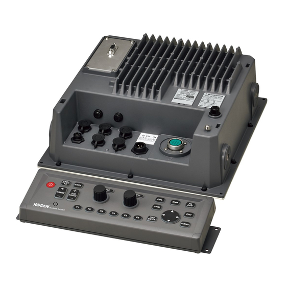
Page 102: External View
Chapter 6 Attached Table MDC-2000BB Series External View MRM-112 Unit: mm (inch) Plan view Side view Weight: 5.1kg (11.2lb) MRO-112 Unit: mm (inch) Plan view Weight: 0.94kg (2.1lb) 0093120012-01... - Page 103 MDC-2000BB Series Chapter 6 Attached Table RB804 Unit: mm (inch) Weight: 8.3kg (18.3lb) 0093120012-01...
- Page 104 Chapter 6 Attached Table MDC-2000BB Series RB805 Unit: mm (inch) Weight: 10kg RB806 with RW701A-03/04 Unit: mm (inch) Weight: 0093120012-01...
- Page 105 MDC-2000BB Series Chapter 6 Attached Table RB807/RB808/RB717A and RB718A with RW701A-04/06 Unit: mm (inch) Weight: RB807/RB808: 24kg/(53lb) ・・・ 4Feet (RW701A-04) 26kg/(57.5lb) ・・・ 6Feet (RW701A-06) 22.5kg/(49.6lb) ・・・ 4Feet (RW701A-04) RB717A/RB718A: 24.5kg/(54lb) ・・・ 6Feet (RW701A-06) 0093120012-01...
- Page 106 - This page intentionally left blank.-...
-
Page 107: Chapter 7 Principle Of Radar System
MDC-2000BB Series Chapter 7 Principle of radar system Chapter 7 Principle of radar system What is the radar system? The radar system is a navigation device that transmits a very high frequency radio wave referred as microwave from antenna. The radar then receives the radio wave reflected by target(s) (e.g. other ship, buoy, island, etc) via the same antenna and converts the received radio wave to electronic signals and sends these signals to the Display unit. -
Page 108: Characteristics Of Radar Radio Wave
Chapter 7 Principle of radar system MDC-2000BB Series Characteristics of radar radio wave The radio wave propagates slightly along the ground (primarily line of sight). This characteristic varies depending on the density of atmosphere but generally calculated according to the formula as shown below, considering that the distance with radar sight D is about 6% longer than the distance with optical sight. - Page 109 MDC-2000BB Series Chapter 7 Principle of radar system ● Virtual image The image of a large physical object in a close proximity may appear in two different orientations. One is a real image and the other is a false image caused by wave reflected on the chimney stack or the mast, etc.
-
Page 110: Radar Interference
Chapter 7 Principle of radar system MDC-2000BB Series ● False image by sidelobe The microwave beam radiated from the antenna has a side lobe in different direction than that of the main beam. Since this side lobe is lower than that of main beam, the effect is negligible for targets at a long range, but a close, strong reflecting target may cause false image in a circular arc shape.
Need help?
Do you have a question about the MDC-2000BB Series and is the answer not in the manual?
Questions and answers