Table of Contents
Advertisement
Quick Links
Download this manual
See also:
Installation Manual
Advertisement
Table of Contents

Subscribe to Our Youtube Channel
Related Manuals for Koden MDC-5004


Summary of Contents for Koden MDC-5004
-
Page 5: Document Revision History
No part of this publication may be reproduced, transmitted, translated in any from by any means without the written permission of Koden Electronics Co., Ltd. The technical descriptions contained in this publication are subject to change without notice. Koden assumes no responsibility for any errors, incidentals or consequential damages caused by misinterpretation of the descriptions contained in this publication. -
Page 6: Important Notice
Koden is not liable for damages of accompaniment (change/loss of memorized content, loss of business profit, stop of business) arisen from use or failure of our products. If the stored data are changed or lost, irrespective of causes of troubles and damages, Koden is not liable for them. ... -
Page 7: For Your Safe Operation
MDC-5000 Series For Your Safe Operation For Your Safe Operation Symbols used in this Operation Manual This manual uses the following symbols. Understand the meaning of each symbol and implement the maintenance and inspection. Symbol Meaning Warning Symbol This symbol denotes that there is a risk of death or serious injury when not dealt with it correctly. - Page 8 For Your Safe Operation MDC-5000 Series Caution related to Equipment Caution, high voltage inside. High voltage that may cause severe injury or death is present. High voltage remains in circuit even after power is turned off. High voltage circuit has a protective cover with a warning label. Make sure to turn off power and discharge capacitors before working on the system.
- Page 9 Specified power density and distance from the radar (in accordance with the provision as specified in IEC 60945) Model name Transmission power / 100W/m 50W/m 10W/m Antenna length MDC-5004 4kW / 3 feet Antenna 0.9 m 1.3 m 2.8 m 4kW / 4 feet Antenna 1.0 m 1.4 m 3.1 m...
- Page 10 IEC 60945) Nom Modèle Puissance de transmission 100W/m 50W/m 10W/m / longueur d’antenne MDC-5004 4kW / Antenne 3 pieds 0.9 m 1.3 m 2.8 m 4kW / Antenne 4 pieds 1.0 m 1.4 m 3.1 m...
- Page 11 MDC-5000 Series For Your Safe Operation Warning Statements related to FCC and IC rules IC RSS-GEN, Sec 8.3 Warning Statement- (Required for Transmitters w/ detachable antennas) ENGLISH: This radio transmitter (identify the device by certification number, or model number if Category II) has been approved by Industry Canada to operate with the antenna types listed below with the maximum permissible gain and required antenna impedance for each antenna type indicated.
- Page 12 For Your Safe Operation MDC-5000 Series IC RSS-102, Sec 2.6 Warning Statement Requirements ENGLISH: The applicant is responsible for providing proper instructions to the user of the radio device, and any usage restrictions, including limits of exposure durations. The user manual shall provide installation and operation instructions, as well as any special usage conditions, to ensure compliance with SAR and/or RF field strength limits.
- Page 13 MDC-5000 Series For Your Safe Operation Warning statement regarding RF exposure compliance ENGLISH: The user manual of devices intended for controlled use shall also include information relating to the operating characteristics of the device; the operating instructions to ensure compliance with SAR and/or RF field strength limits;...
- Page 14 For Your Safe Operation MDC-5000 Series particular installation. If this equipment does cause harmful interference to radio or television reception, which can be determined by turning the equipment off and on, the user is encouraged to try to correct the interference by one or more of the following measures: - Reorient or relocate the receiving antenna.
- Page 15 MDC-5000 Series For Your Safe Operation Do not disassemble or modify. It may lead to trouble, fire, smoking or electric shock. In case of trouble, contact our dealer or our company. In case of smoke or fire, switch off the power in the boat and the power of equipment.
-
Page 16: Break In Procedure Of Stored Radar
Break in procedure of stored radar MDC-5000 Series Break in procedure of stored radar Following procedure is recommended for “Break In” of the stored radar. Otherwise the radar sometimes exhibits unstable transmitting operation such as arcing at its initial operation after long period of storage and make the operation more difficult. -
Page 17: Used Battery And Radar Disposal
MDC-5000 Series Used battery and radar disposal Used battery and radar disposal A high-energy density lithium ion battery is installed in this radar. Improper disposal of a lithium ion battery is discouraged as the battery has a possibility of short-circuiting. If it gets wet, the generation of heat, explosion or ignition may occur resulting in an injury or fire. -
Page 18: In Case No Heading And Speed Signals Are Input From Navigation Equipment
In case no Heading and Speed signals MDC-5000 Series In case no Heading and Speed signals are input from navigation equipment When no Heading and Speed signals are input from navigation equipment (in case not connected), this radar gives alarms and warning messages at lower right of the display, if the radar is started up factory default settings. -
Page 19: Table Of Contents
MDC-5000 Series Contents Contents Document Revision History ....................... i Important Notice ........................ii For Your Safe Operation ......................iii Break in procedure of stored radar ..................xii Used battery and radar disposal .................... xiii In case no Heading and Speed signals are input from navigation equipment....... xiv Contents .......................... -
Page 20: Contents
Contents MDC-5000 Series Optimized value setup method ................. 2-4 Change range scale ....................2-5 Change range unit (NM / km / sm) ................2-5 Adjust receiver gain (GAIN) ..................2-6 Selection of MAN GAIN and AUTO GAIN ..............2-6 AUTO adjustment of GAIN ..................2-6 MAN adjustment of GAIN .................. - Page 21 MDC-5000 Series Contents 2.18 Target trail ....................... 2-29 Relative display (R) ....................2-31 True display (T) ...................... 2-31 2.19 Off Center ........................ 2-32 2.20 Function key usage ....................2-33 2.21 Set picture mode ..................... 2-34 2.22 Echo process ......................2-35 Correlation image echo process ................
- Page 22 Contents MDC-5000 Series Chapter 4 Target (AIS and TT) ................. 4-1 Common setting ......................4-1 VECTOR REL/TRUE ....................4-1 CPA/TCPA alarm ..................... 4-2 Set AIS ID DISP TYPE ..................... 4-2 Set TT ID DISP TYPE ....................4-3 Set ID DISP SIZE ..................... 4-3 Set Input range ......................
- Page 23 MDC-5000 Series Contents Target track past position display ................6-2 COAST LINE ......................6-3 How to edit ....................... 6-4 How to move ......................6-5 How to add ....................... 6-7 How to delete ......................6-8 How to clear ......................6-8 NAV LINE ........................6-9 ROUTE ........................
- Page 24 Contents MDC-5000 Series Chapter 8 Principal of radar system ................. 8-1 What is radar system?....................8-1 Side lobe ........................8-1 Beam width ....................... 8-2 Characteristics of radar radio wave ................8-2 Target hardness reflected ..................8-2 Radar shadow ......................8-3 False image ......................
-
Page 25: Introduction
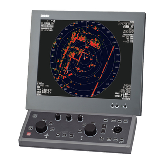
MDC-5000 Series Introduction Introduction The MDC-5000 series is a compact and high performance shipboard radar system consisting of the Antenna & Scanner unit with a transmit power of 4kW/6kW/12kW/25kW, Processor unit and Operation unit. For this radar, its multi functions and high performance are accomplished with microcomputer technology as well as an image processing in the newly developed radar-dedicated LSI (Large Scale Integration). -
Page 26: Configuration Items
Configuration items MDC-5000 Series Configuration items System configuration MDC-5004 Name Type Antenna RW701A-03:3feet RW701A-04:4feet RW701A-06:6feet Scanner RB806 Processor unit MRM-110 Operation unit with connecting cable MRO-110 Connecting cable 242J159098B-15M DC power cable CW-259-2M Spare parts SP-MRM-110 Installation material M12-BOLT.KIT Installation material CONNECTOR.KIT... -
Page 27: Option List
Antenna unit – CW-845-* With connectors on the both sides Processor unit *: 20M, 30M, 40M, For MDC-5006/5012/5025 connecting cable 50M, 65M, 100M 242J159098*-**M With connectors on the both sides **: 20M, 30M, **M For MDC-5004 (100m max) 0093153004-00 xxiii... - Page 28 - This page intentionally left blank.-...
-
Page 29: Chapter 1 Display And Operation
MDC-5000 Series Chapter 1 Display and Operation Chapter 1 Display and Operation 1.1 Radar Display Upper right corner Upper left corner Heading line EBL2 EBL1 VRM1 VRM2 CURSOR Alarm status Range Rings Lower left corner Lower right corner Upper left corner Range scale Range Rings MODE... -
Page 30: Upper Right Corner
Chapter 1 Display and Operation MDC-5000 Series Upper right corner TUNE setting Date and Time Heading Own ship data STW or SOG Own ship position Gain mode setting Sea mode setting Rain mode setting Picture mode setting PROCESS setting ENHANCE setting Interference Rejection setting VIDEO mode setting Lower left corner... -
Page 31: Info Disp
MDC-5000 Series Chapter 1 Display and Operation INFO DISP Move cursor on the < INFO box at lower right corner of the display, and press ENT key. Four “INFO DISP” windows appear, and various navigation data will be shown. Move cursor on the INFO > box at lower left of the “INFO DISP” window, and press ENT key. All “INFO DISP”... -
Page 32: Alarm Status
Chapter 1 Display and Operation MDC-5000 Series Alarm status The icon of alarm status will be displayed at the lower left of the display. Alarm icon Icon name Setting method (Refer to Chapter 3 Alarm) Echo alarm Refer to 3.1 Echo alarm Map area alarm Refer to 3.2 Map area alarm Nav line cross alarm... - Page 33 MDC-5000 Series Chapter 1 Display and Operation - This page intentionally left blank.- 0093153004-00...
-
Page 34: Operation Unit
Chapter 1 Display and Operation MDC-5000 Series 1.2 Operation Unit Key/knob name Contents POWER ON/OFF key Turn on and off the power. STBY/TX key Transmission on and off. DAY/NIGHT key Change echo color, day or night. EBL1 key EBL1 on and off EBL2 key EBL2 on and off BRILL key... - Page 35 MDC-5000 Series Chapter 1 Display and Operation ENH key Change echo enhance value MENU key Turn MENU on and off ACQ key Start manual TT acquisition ENT key Key most often used to make a selection RANGE key Change radar range scale. SP/LP key Change transmission pulse width.
-
Page 36: Menu Usage
Chapter 1 Display and Operation MDC-5000 Series Menu usage Turn MENU on and off Press MENU key, “Menu” display on the lower left of the display. “Menu” display is turned off by pressing MENU key again. Select menu item Press MENU key and “Main menu” will show on the display. Select one of main menu items by moving the joystick up or down. -
Page 37: Cursor Access Usage
MDC-5000 Series Chapter 1 Display and Operation Note: About the shaded menu: [INTER-SWITCH] in [SYSTEM] menu, and [SECTOR MUTE], [BACKUP], [TOTAL HOUR] and [TX HOUR] in [MAINTENANCE] menu are not available during transmission, therefore they are the shaded menu. Cursor Access usage Basic radar functions can be operated by using the joystick and ENT key without using menu. - Page 38 - This page intentionally left blank.-...
-
Page 39: Chapter 2 Radar Basic Operation
Wait for 120 sec. (*1) or 180 sec. (*2) until preheating countdown time has disappeared, and status changes from WAIT to STANDBY at the upper left of the display. (*1) MDC-5004/5006/5012 (*2) MDC-5025 The brilliance of the display is set to the previous value of the last power off. -
Page 40: Change Brilliance
Chapter 2 Radar Basic Operation MDC-5000 Series Change Brilliance Display Brilliance Press BRILL key. The BRILL adjustment window will appear in the upper left of the display. BRILL adjustment window Turn EBL knob clockwise to increase the display brilliance. Turn EBL knob counterclockwise to decrease the display brilliance. The display brilliance can also be changed in five steps by pressing EBL knob. -
Page 41: Transmission
MDC-5000 Series Chapter 2 Radar Basic Operation Transmission Transmission ON After preheating time countdown is completed, the radar can be placed in transmit mode. Press STBY/TX key, or select the STANDBY box at the upper left corner of the display using joystick and press ENT key. -
Page 42: Tuning Method
Chapter 2 Radar Basic Operation MDC-5000 Series Tuning method The transmitting and receiving frequency of this radar may become detuned by environmental changes. This result in “detuning” of the gain and the same echo images may show weaker, even if the setup is the same as before. -
Page 43: Change Range Scale
Cursor point Model-specific ranges are as shown below. Model name MDC-5025 (Max. output: 25 kW) MDC-5012 (Max. output: 12 kW) MDC-5006 (Max. output: 6 kW) MDC-5004 (Max. output: 4 kW) Range(NM) 96** 0.125 0.25 0.75 * 32NM and 64NM is for 6kW / 12kW only. -
Page 44: Adjust Receiver Gain (Gain)
Chapter 2 Radar Basic Operation MDC-5000 Series Adjust receiver gain (GAIN) It is recommended to adjust [GAIN] in the upper right side of the display to have the evenly scattered vague background noise with low intensity in the PPI. Lower than required [GAIN] may result in missing small vessels and buoys. Higher [GAIN] than required may result in difficult discrimination between small ships and densely displayed high level background noise. -
Page 45: Man Adjustment Of Gain
MDC-5000 Series Chapter 2 Radar Basic Operation MAN adjustment of GAIN When MAN GAIN is selected, GAIN can be adjusted manually. Turn GAIN knob clockwise to increase receiving gain. Turn GAIN knob counterclockwise to decrease receiving gain. Gain Down Note: •... -
Page 46: Reject Sea Clutter (Anti-Sea)
Chapter 2 Radar Basic Operation MDC-5000 Series Reject sea clutter (anti-SEA) MAN (manual) SEA and AUTO (automatic) SEA are provided for anti-SEA function. On the rough sea, SEA clutter noise appears around antenna position (center spot), and short distant targets are masked and not recognizable. -
Page 47: Auto Adjustment Of Sea
MDC-5000 Series Chapter 2 Radar Basic Operation AUTO adjustment of SEA When AUTO SEA is set, anti-SEA is adjusted automatically. Note: AUTO SEA may erase weak target echoes. If excessive sea clutter erasing or too much clutter is observed, turn SEA knob clockwise or counterclockwise to adjust AUTO SEA effectively. If not setup properly, adjust it by referring to 4.4.3 Setup GAIN MIN and MAX mode of Installation manual. -
Page 48: Reject Rain/Snow Clutter (Anti-Rain)
Chapter 2 Radar Basic Operation MDC-5000 Series Reject rain/snow clutter (anti-RAIN) In rain or snow, targets become hard to be seen as a result of unwanted weather reflection. Rain or snow image appears as a large target echo with surrounding mid gradation rim. Anti-RAIN is available MAN and CFAR. -
Page 49: Changing Method Of Cfar And Man
MDC-5000 Series Chapter 2 Radar Basic Operation Changing method of CFAR and MAN By joystick Move cursor on the MAN or CFAR display (whichever is shown) at right side of [RAIN] on the top of the display. Press ENT key to alternate CFAR and MAN. By Function key operation When the Selection of RAIN control mode is registered with a FUNCTION key (RAIN knob, F1, F2 or F3 key), when a FUNCTION key is pressed, CFAR and MAN RAIN changes alternately. -
Page 50: Rain Man (Manual) Adjustment
Chapter 2 Radar Basic Operation MDC-5000 Series RAIN MAN (manual) adjustment After adjusted anti-SEA & RAIN MAN After adjusted anti-SEA Turn RAIN knob clockwise to increase anti-clutter effect. Turn RAIN knob counterclockwise to decrease anti-clutter effect. Turn GAIN knob clockwise until sea clutter is visible on the display. RAIN Weak Strong... -
Page 51: Change Transmission Pulse Width (Sp/Lp)
MDC-5000 Series Chapter 2 Radar Basic Operation Change transmission pulse width (SP/LP) This radar provides a function capable of achieving suitable target detection by manually changing the transmission pulse width. Eight different pulse widths are available. 4 kW 6 kW / 12 kW / 25 kW IF Band width Pulse width Pulse width... -
Page 52: Select Display Mode
Chapter 2 Radar Basic Operation MDC-5000 Series 2.10 Select Display Mode The display mode is a combination of the bearing indication and the target motion indication. The bearing is indicated in three ways: HUP, CUP and NUP. The target motion is indicated in two ways: RM and TM. Press MODE key. -
Page 53: For C Up (Course Up Mode)
MDC-5000 Series Chapter 2 Radar Basic Operation For C UP (Course up mode) When choosing Course up mode, current heading becomes the course at the top of the display and a moving heading line indicates actual. This mode is used to navigate towards a specified course. It easily shows any deviation of own ship from the specified course. -
Page 54: For N Up (North Up Mode)
Chapter 2 Radar Basic Operation MDC-5000 Series For N UP (North up mode) This mode always keeps true north at the top of the display. A north oriented representation makes it easy to reference with a chart. Target 1 Heading Land Target 2 Note:... -
Page 55: For Relative Motion (Rm) And True Motion (Tm)
MDC-5000 Series Chapter 2 Radar Basic Operation For relative motion (RM) and true motion (TM) Relative motion (H UP , C UP , N UP ) fixes your antenna position at the center of the display, and indicates the motion of targets that surround your antenna position. Your antenna position is displayed at the center. -
Page 56: Reset True Motion
Chapter 2 Radar Basic Operation MDC-5000 Series N-UP or C-UP TM mode is selected, antenna position (own ship position) moves to opposite side of heading direction, and begins to show the true motion image. When antenna position (own ship position) reaches center of the range scale, own ship position is to reset to the course over water or to the opposite direction of the course over ground. -
Page 57: Ground And Sea Stabilization
MDC-5000 Series Chapter 2 Radar Basic Operation 2.11 Ground and Sea stabilization STAB MODE is a function to select speed for movement calculation for True trail, TT (ATA), Past position and True motion (TM). Press MENU key to display “Menu”. Select [DISPLAY] =>... -
Page 58: Measurement Of Distance By Rr And Vrm
Chapter 2 Radar Basic Operation MDC-5000 Series 2.12 Measurement of distance by RR and VRM There are three ways to measure distance to a target: Range Rings, Cursor or VRM. Display Range Rings (RR) Range rings (RR) are markers displayed at the specified distance from reference point. They are used as a rough indication of the distance to a target. -
Page 59: Measurement Range (Vrm: Variable Range Marker)
MDC-5000 Series Chapter 2 Radar Basic Operation Measurement Range (VRM: Variable Range Marker) Two variable range markers [VRM1] and [VRM2] are provided. Turn VRM knob and lay each circle on the desired target to read the distance to the target on the display. -
Page 60: Measurement Of Bearing By Ebl
Chapter 2 Radar Basic Operation MDC-5000 Series 2.13 Measurement of bearing by EBL This feature is used for measuring the bearing of the target from the base point (reference point for default value.) Two electronic bearing lines [EBL1] and [EBL2] are provided. Turn EBL knob and lay each bearing line on the desired target and read the bearing on the display. -
Page 61: Using The Ebl/Vrm Offset
MDC-5000 Series Chapter 2 Radar Basic Operation Using the EBL/VRM OFFSET EBL (and VRM) base point can be changed to any position other than the initial reference point. By changing the base point, the bearing from a random target can be measured. Display the EBL (and VRM) for which the base point is required to be changed. -
Page 62: Bearing Mode Set Up
Chapter 2 Radar Basic Operation MDC-5000 Series 2.14 Bearing mode set up This menu is used to change the bearing mode in EBL, PI, Bearing scale and CURSOR. The settings available in the true bearing with the true north of 000 degree, and in the relative bearing with the heading of 000 degree. -
Page 63: Measurement Of Distance/Bearing By Pi
MDC-5000 Series Chapter 2 Radar Basic Operation 2.15 Measurement of distance/bearing by PI This function is used to display straight Parallel Index (PI) lines on one or both sides of the vessel, range and bearing of which can be manipulated by following procedures. PI display side setting [NAV TOOL] =>... -
Page 64: Change Color And Brightness (Day/Night)
Chapter 2 Radar Basic Operation MDC-5000 Series 2.16 Change color and brightness (Day/Night) This function is used to change default echo, trail and all data color and contrast for day and night mode. DAY/NIGHT mode can be changed directly by pressing DAY/NIGHT key. Setup color Select the mode (Day or Night) by pressing DAY/NIGHT key, color palette of which you would like to change. -
Page 65: Setup User1 And User2 Color
MDC-5000 Series Chapter 2 Radar Basic Operation Setup USER1 and USER2 color Select the mode (Day or Night) by pressing DAY/NIGHT key, color palette of which you would like to change. Press MENU key to display “Menu”. Select [BRILL] => select [USER1 COLOR] or [USER2 COLOR]. After selecting the each item, and after adjusting each item with joystick, press ENT key. -
Page 66: Setup Brightness
Chapter 2 Radar Basic Operation MDC-5000 Series Setup brightness This is to set up brightness of ECHO, TRAIL, BKGND, OS TOOL, TGT, MAP, CURSOR, DATA and MENU/ALERT. Default value of these items is 100 (max). For safety reason, brightness cannot be adjusted to less than 20. Select the mode (day or night) by pressing DAY/NIGHT key, brightness of which you would like to change. -
Page 67: Remove The Heading Line/Navigation Data
MDC-5000 Series Chapter 2 Radar Basic Operation 2.17 Remove the heading line/navigation data This function is used when a target is overlapped with a heading line and hard to be distinguished. Press OFF key to temporarily hide the heading line. For safety reason, the heading line disappears only while the key is pressed. - Page 68 Chapter 2 Radar Basic Operation MDC-5000 Series [TIME]: This is to set up the time of the trail to be displayed. Initial set up time: OFF, 30sec, 1min, 3min, 6min, 12min, 30min, 60min, PERM Time setting can be changed by [STARTUP] => [TIME] menu operation [SHAPE]: Three types of trail shapes available, as shown below.
-
Page 69: Relative Display (R)
MDC-5000 Series Chapter 2 Radar Basic Operation Relative display (R) The target trail is displayed as result of sum of vector (course and speed) of the target ship and your ship. When your ship is on the projected course of this trail, it shows that a collision may occur in future. This display is useful to help detect a dangerous situation. -
Page 70: Off Center
Chapter 2 Radar Basic Operation MDC-5000 Series 2.19 Off Center This function is used to get larger view in heading direction. Two ways “OFF CENTER” can be setup. [CURSOR]: Off-centering to CURSOR direction. [OPPOSITE]: Off-centering to the stern direction. Press MENU key to display “Menu”. Select [DISPLAY] =>... -
Page 71: Function Key Usage
MDC-5000 Series Chapter 2 Radar Basic Operation 2.20 Function key usage For quick function access, there are six dedicated function keys provided on this radar (“F1”, “F2”, “F3”, “RAIN”, “SEA” and “GAIN”). You can switch to a pre-specified function by pressing each key. Press MENU key to display “Menu”. -
Page 72: Set Picture Mode
Chapter 2 Radar Basic Operation MDC-5000 Series 2.21 Set picture mode It is necessary to make adjustment to the radar picture as environment and sea condition changes. The Picture mode can quickly change for different settings, [PROCESS], [ENH], [IR] and [VID], depending on the situation. -
Page 73: Echo Process
MDC-5000 Series Chapter 2 Radar Basic Operation 2.22 Echo process Echo process mode is used to suppress of sea, rain and snow clutter and the target appears on the display. Echo process mode is used correlation method. Five types of C1, C2, C3, A1 and A2 are available. -
Page 74: Echo Enhance
Chapter 2 Radar Basic Operation MDC-5000 Series 2.23 Echo enhance This function is to enlarge an image in the direction of distance/bearing. Small ships and remote targets can be enlarged to be easier to see. [ENHANCE] can be changed directly at the upper right of the display. Echo enhance is executed by pressing ENH key, or move the cursor to set value window of OFF, 1, 2, 3 or 4 of [ENHANCE] at the upper right part of the display. -
Page 75: Interference Rejection (Ir)
MDC-5000 Series Chapter 2 Radar Basic Operation 2.24 Interference rejection (IR) This feature is used to reject interference from other radars. Radar transmissions on same frequency band can cause interference noise on the display depending on its transmitted power. This noise pattern appearance varies case by case, but is usually spiral shape or like the spokes of a wheel in shape. -
Page 76: Echo Color Rejection
Chapter 2 Radar Basic Operation MDC-5000 Series 2.26 Echo color rejection This radar has a function to remove a color selected by menu operation. This effect is to show the strong signal image clearly and to delete the unwanted signal such as noise. Press MENU key to display “Menu”. - Page 77 MDC-5000 Series Chapter 2 Radar Basic Operation SP mode LP mode Range 0.125 S1 0.25 S1 S2 S1 S2 0.5 S1 S2 M1 M2 S1 S2 M1 M2 0.75 S1 S2 M1 M2 S1 S2 M1 M2 1.5 S1 S2 M1 M2 S1 S2 M1 M2 S2 M1 M2 S2 M1 M2...
-
Page 78: Inter-Switch
Chapter 2 Radar Basic Operation MDC-5000 Series 2.28 Inter-switch Inter-switch is a way to setup two radars to be connected together. Note: If either radar fails while two radars are in use, then set the [INTER-SWITCH] menu of the working radar to [INDEPENDENT MASTER] and use it independently. Refer to “3.4.8 Cable connection for inter-switch”... - Page 79 MDC-5000 Series Chapter 2 Radar Basic Operation DUAL MASTER: Connection topology is the same as the above-mentioned INDEPENDENT (MASTER) and INDEPENDENT (SLAVE), and the data cable is necessary. By this way, either radar can control the antenna. The radar to which the antenna is connected is DUAL (MASTER).
-
Page 80: Cursor Data
Chapter 2 Radar Basic Operation MDC-5000 Series 2.29 Cursor data Cursor data is displayed in distance and bearing at lower right of the display. In addition, it can also be displayed in latitude and longitude position. Bearing Distance Latitude Longitude CURSOR setting menu Press MENU key to display “Menu”. -
Page 81: Setup Own Ship Outline
MDC-5000 Series Chapter 2 Radar Basic Operation 2.30 Setup own ship outline Setup ship outline Press MENU key to display “Menu”. Select [NAV TOOL] => [SHIP OUTLINE] => [SHIP OUTLINE] => [ON] or [OFF], and press ENT key. [ON]: Display own ship outline. [OFF]: Non display own ship outline. -
Page 82: Ferry Mode
Chapter 2 Radar Basic Operation MDC-5000 Series 2.31 FERRY MODE It is a function to use a river for by coming and going ferry etc. It becomes effective at H UP, and the letter of the FERRY appears on the screen while using it. Press MENU key to display “Menu”. -
Page 83: Display Setup
MDC-5000 Series Chapter 2 Radar Basic Operation 2.32 Display setup 2.33.1 ALL PPI mode ALL PPI function is to display radar echo images, trails, maps and c-map chart on all screens (excluding menu area and own ship’s information area). Press MENU key to display “Menu”. Select [DISPLAY] =>... -
Page 84: Info Disp
Chapter 2 Radar Basic Operation MDC-5000 Series 2.33.3 INFO DISP This function selects the information to display for “INFO DISP”. There are four “INFO DISP” areas. (UPERP, MIDDLE1, MIDDLE2 and BOTTOM) “INFO DISP” is displayed right side of the display. Press MENU key to display “Menu”. -
Page 85: Chapter 3 Alarm
MDC-5000 Series Chapter 3 Alarm Chapter 3 Alarm This function is used to monitor hazardous targets such for collision prevention. Collision avoidance It is strongly recommended to maneuver the ship for collision avoidance based on true and dependable SOG and COG information. This is because ship's heading and running speed against water may be different from the actual ship's movement due to foreign or mostly natural environmental effect such as wind, current, wave etc. - Page 86 Chapter 3 Alarm MDC-5000 Series Blue dotted line of echo alarm area BRG REL WIDTH DEPTH EBL knob and VRM knob are used for setup. ECHO ALARM BRG REL 338.0˚ WIDTH 115.0˚ 006.0NM DEPTH 002.0NM Orange dashed circle line Press EBL1 or EBL2 key, and select an item to be set between [BRG REL] and [WIDTH] by using EBL knob.
-
Page 87: Map Area Alarm
MDC-5000 Series Chapter 3 Alarm Map area alarm Map area alarm function provides alarm display when echo enters or leaves from the MAP AREA. Press MENU key to display “Menu”. Select [ALARM] => [MAP AREA ALARM] => select [IN] or [OUT], and press ENT key. [IN] mode: When the echo enters a specified map area, alarm message will be displayed at lower right of the display and an alarm will sound. -
Page 88: How To Move Map Area
Chapter 3 Alarm MDC-5000 Series The procedures to input plural divided map areas in the memory of same block number are as follows. (Example) After input the one map area (from x-1 to x-3), please input the start point of the new map area (x-4). -
Page 89: How To Add Data To Map Area
MDC-5000 Series Chapter 3 Alarm Repeat operation of clause 2 to 4 mentioned previously. Press Cursor ACQ key. Press New position ENT key. x: Block number (1 to 10) When move operation is completed, press MENU key, numerical marks on the display will disappear, and map area alarm function will be active. -
Page 90: How To Delete The Data Of Map Area
Chapter 3 Alarm MDC-5000 Series How to delete the data of map area There are two methods to delete map area alarm position. First method is to delete the point that is selected by cursor, second is to select the number from the menu. Example: Cursor method Press MENU key to display “Menu”. -
Page 91: Nav Line Cross
MDC-5000 Series Chapter 3 Alarm Nav line cross Nav line cross function enables to attract attention for safety navigation with alarm display when own ship crosses the course preliminarily set (by cursor or latitude/longitude input). Press MENU key to display “Menu”. Select [ALARM] =>... -
Page 92: How To Move Nav Line
Chapter 3 Alarm MDC-5000 Series The procedures to input plural divided nav line in the memory of same block number are as follows. (Example) After input the one nav line (from x-1 to x-3), please input the start point of the new nav line (x-4). Press OFF key to divide the start point (x-4) from the last point (x-3). -
Page 93: How To Add
MDC-5000 Series Chapter 3 Alarm When move operation is completed, press MENU key, numerical marks on the display will disappear, and nav line cross alarm will be activated. How to add There are two methods to add nav line cross alarm position. First method is to use cursor, second is to input latitude/longitude by the menu. -
Page 94: How To Delete
Chapter 3 Alarm MDC-5000 Series How to delete There are two methods to delete the data of nav line cross alarm position. First method is to delete the point that is selected by cursor directly, second is to select the number from the menu. Example: Cursor method Press MENU key to display “Menu”. -
Page 95: Chapter 4 Target (Ais And Tt)
MDC-5000 Series Chapter 4 Target (AIS and TT) Chapter 4 Target (AIS and TT) Common setting VECTOR REL/TRUE The course and speed are indicated as vector after tracking is established. Two types of display mode are available: relative display (REL) and true display (TRUE). REL: This vector adds the course/speed of a target to the course/speed of own ship. -
Page 96: Cpa/Tcpa Alarm
Chapter 4 Target (AIS and TT) MDC-5000 Series [STAB INDICATOR]: This function is to display the mark of GND or SEA stabilization on the end of own ship vector. Symbol Symbol name GNG indicator (Double arrowhead) SEA indicator (Single arrowhead) STAB INDICATOR is displayed only when VECTOR is displayed. -
Page 97: Set Tt Id Disp Type
MDC-5000 Series Chapter 4 Target (AIS and TT) Set TT ID DISP TYPE ID can be displayed with TT (ATA) target. Set items: NUMBER Set ID DISP SIZE This menu is used to specify display ID size. Selection values: X-SMALL, SMALL, MEDIUM, LARGE Set Input range This is to set up the operation range of TT (ATA) and AIS. -
Page 98: Automatic Acquisition Area
Chapter 4 Target (AIS and TT) MDC-5000 Series OFF: Association is turned off. TT: Symbols of both TT (ATA) and AIS are associated to TT (ATA). However when the target of AIS is sleeping target it is not associated. AIS: Symbols of both TT (ATA) and AIS are associated to AIS. However when the target of AIS is sleeping target it is not associated. - Page 99 MDC-5000 Series Chapter 4 Target (AIS and TT) Blue dotted line of auto acq area BRG REL WIDTH DEPTH EBL knob and VRM knob are used for setup. AUTO ACQ AREA BRG REL 338.0˚ WIDTH 115.0˚ 006.0NM DEPTH 002.0NM Orange dashed circle line Press EBL1 or EBL2 key, and select an item to be set between [BRG REL] and [WIDTH] by using EBL knob.
-
Page 100: Ais
Chapter 4 Target (AIS and TT) MDC-5000 Series The AIS communicates with other ships via VHF (Very High Frequency) radio by transmitting your ship information and by receiving other ships information. Only AIS data with WGS84 datum is accepted. If AIS data has no datum or if datum is other than WGS84, then the warning of [AIS datum is not WGS84] appears. -
Page 101: Ship Outline
MDC-5000 Series Chapter 4 Target (AIS and TT) Ship outline Ship outline function is displayed only when OUTLINE data is included in the target information received by AIS. Ship outline is not displayed if it is too small in size of the display, and it is not displayed when own ship outline is OFF. -
Page 102: Ais Filter
Chapter 4 Target (AIS and TT) MDC-5000 Series AIS filter When there are many AIS targets, the display may become unclear. In that case, by setting AIS FILTER, it is possible to hide unnecessary sleeping targets or to display the necessary targets only, and the clear view of the target can be achieved. -
Page 103: Types Of Ais Target Symbol
MDC-5000 Series Chapter 4 Target (AIS and TT) Types of AIS target symbol The following symbols are overlapped on target. Symbol Symbol name Sleeping target Sleeping target without HDG. Sleeping target with neither reported HDG nor COG. Activated target Activated target without HDG. Activated target with neither reported HDG nor COG. - Page 104 Chapter 4 Target (AIS and TT) MDC-5000 Series Physical AIS AtoN Basic shape Emergency North cardinal Racon wreck mark mark East cardinal South cardinal West cardinal mark mark mark Starboard hand Port hand mark Isolated danger mark Safe water Special mark (IALA dictionary, topmarks) Off position Racon failure...
- Page 105 MDC-5000 Series Chapter 4 Target (AIS and TT) Safe water Special mark (IALA dictionary, topmarks) Intended location of missing AtoN AIS-SART (AIS Search And Rescue Transponder) BASE AIS SAR aircraft AIS SAR vessel * ID can be displayed with Activated target. 4-11 0093153004-00...
-
Page 106: Tt (Ata)
Chapter 4 Target (AIS and TT) MDC-5000 Series TT (ATA) It is an effective mean for collision avoidance by generating vectors on tracked targets. It is an effective means for collision avoidance to set up CPA/TCPA. If AIS information is available with tracked targets, association increases tracking accuracy. Limitations of the TT function There are the following limitations on use of the target acquisition and tracked target of TT (ATA) functions. -
Page 107: Enable Tt Function
MDC-5000 Series Chapter 4 Target (AIS and TT) Enable TT function This is to enable TT function. Press MENU key to display “Menu”. Select [TARGET] => [TT] => [TT] => [ON], and press ENT key. Note: • Pressing ACQ key in [OFF] state automatically turns to [ON] state. •... -
Page 108: Delete Tt Target
Chapter 4 Target (AIS and TT) MDC-5000 Series Delete TT target There are two methods to delete TT target. First method is to use menu operation, second is to use cursor operation. Menu operation This is to delete the TT target selected [SELECT ID] and [DELETE] function. Press MENU key to display “Menu”. -
Page 109: Types Of Tracked Target Symbol
MDC-5000 Series Chapter 4 Target (AIS and TT) Types of tracked target symbol The following symbols are overlaid on target. Symbol Symbol name Radar target in acquisition state Radar target in acquisition state - Automatic acquisition Blink in (Red clolor) 0.5 sec. - Page 110 - This page intentionally left blank.-...
-
Page 111: Chapter 5 Nav Tool
MDC-5000 Series Chapter 5 Nav tool Chapter 5 Nav tool Guard line Guard line function is a function that displays parallel lines to the heading on both side of own ship. Distance to guard line from own ship can be set from 0 to 10000m (left and right side independently). Press MENU key to display “Menu”. -
Page 112: Hl Blink
Chapter 5 Nav tool MDC-5000 Series HL blink HL BLINK function lets HL marker display blinks every antenna rotation. It is effective to confirm that there is no small targets right under the HL marker. Press MENU key to display “Menu”. Select [NAV TOOL] =>... -
Page 113: Barge Icon
MDC-5000 Series Chapter 5 Nav tool Barge icon This radar is equipped with a barge icon feature that is very helpful for river operation where user can set up the size dimensions of the tow and be able to display it on the display. Press MENU key to display “Menu”. - Page 114 - This page intentionally left blank.-...
-
Page 115: Chapter 6 Map Operation
MDC-5000 Series Chapter 6 Map operation Chapter 6 Map operation MAP function display ON or OFF This is to turn ON/OFF the entire MAP function. Press MENU key to display “Menu”. Select [MAP] => [MAP DISP] => [ON], and press ENT key. It is not displayed as well as HL while OFF key is pressed. -
Page 116: How To Clear Own Ship Past Track
Chapter 6 Map operation MDC-5000 Series When the recording of the own ship past track is started, move the cursor to the STOP of the OS PAST TRK at the lower left of the display, and press the ENT key. When the recording of the own ship past track is completed, move the cursor to the REC of the OS PAST TRK at the lower left of the display, and press the ENT key. -
Page 117: Coast Line
MDC-5000 Series Chapter 6 Map operation Select [STYLE] => select style* => press ENT key. *Line style: Select [PLOT INT] => and press ENT key after selecting the set up value. Selection values: OFF, 2sec, 15sec, 30sec, 1min, 3min, 5min Select [PLOT NUMBER] =>... -
Page 118: How To Edit
Chapter 6 Map operation MDC-5000 Series ADD: Insert a position data. (CURSOR, BLOCK NUMBER) DELETE: Delete a position data. (CURSOR, BLOCK NUMBER) CLEAR: Clear a selected block number coast line data. How to edit (1) CURSOR OPERATION Press MENU key to display “Menu”. Select [MAP] =>... -
Page 119: How To Move
MDC-5000 Series Chapter 6 Map operation (2) BLOCK NUMBER OPERATION Press MENU key to display “Menu”. Select [MAP] => [COAST LINE] => [EDIT] => [BLOCK NUMBER] => select [1 to 10] => Following input menu is displayed. NUMBER 0˚ 00.000N 0˚... - Page 120 Chapter 6 Map operation MDC-5000 Series Move cursor on editing and moving cursor data. Press ACQ key. Circle mark will be displayed on the selected coast line and numerical data is shown at coast line info area. Cursor Move cursor to new position, then press ENT key. Cursor Press MENU key to exit MOVE operation.
-
Page 121: How To Add
MDC-5000 Series Chapter 6 Map operation How to add (1) CURSOR OPERATION Press MENU key to display “Menu”. Select [MAP] => [COAST LINE] => [ADD] => [CURSOR] => select [1 to 10] => [GO] and press ENT key. Numerical number is displayed each points of coast line. Move cursor on position that new data is added in just before it. -
Page 122: How To Delete
Chapter 6 Map operation MDC-5000 Series How to delete (1) CURSOR OPERATION Press MENU key to display “Menu”. Select [MAP] => [COAST LINE] => [DELETE] => [CURSOR] => select [1 to 10] => [GO] and press ENT key. Numerical number is displayed each points of coast line. Move cursor on the position deleting. -
Page 123: Nav Line
MDC-5000 Series Chapter 6 Map operation NAV LINE NAV LINE is a function to display Navigation line by inputting Lat/Lon information for each point or using a cursor and ENT key to input the points, user can set 10 lines up to 100 points each. “NAV LINE”... -
Page 124: Route
Chapter 6 Map operation MDC-5000 Series ROUTE The ROUTE function is for display purposes only, user can setup ROUTE on radar display for visual navigation aid. ROUTE can be setup using cursor and ENT key or by inputting Lat/Lon information for each point. -
Page 125: Event Mkr
MDC-5000 Series Chapter 6 Map operation EVENT MKR EVENT MKR function displays various marks on the designated place, and can utilize it for sign, such as a destination, a fishery and a caution area. EVENT MKR set can be done by input of Lat/Lon information or by cursor and ENT key. -
Page 126: Area
Chapter 6 Map operation MDC-5000 Series AREA Area function is for visual navigation where user can input points connected by a line to help with navigation. There are 10 memory blocks for area that can hold up to 100 points each. This function is valid with a minimum input of 3 points which will be connected with a line. -
Page 127: Wpt Id Disp
MDC-5000 Series Chapter 6 Map operation 6.10 WPT ID DISP This function when activated can display WPT name information from external device such as chart plotter or GPS navigator. This applies to all waypoints from WPT and also ROUTE waypoints. When [WPT ID DISP] turned on, ID information will be displayed next to waypoints and when turned off only waypoints without ID information will be displayed. -
Page 128: C-Map Chart Display
Chapter 6 Map operation MDC-5000 Series 6.14 C-MAP chart display This radar can display chart of C-MAP. The CHART and CHART DISP SET menu are displayed when C-MAP chart of SD-card type has been inserted in the lower card reader of the Processor unit. CAUTION: Please ensure that the C-MAP SD-card must be inserted in the lower card reader of the Processor unit. -
Page 129: Chapter 7 System And Maintenance Menu Operation
MDC-5000 Series Chapter 7 System and Maintenance menu operation Chapter 7 System and Maintenance menu operation SYSTEM MENU INTER-SWITCH: Refer to 2.28 Inter-switch TIME SOUND LANG DISP INFO HELP Change UTC/LOCAL time Press MENU key to display “Menu”. Select [SYSTEM] => [TIME] => select [UTC] or [LOCAL], and press ENT key. [UTC / LOCAL] time can be changed directly at the “INFO DISP”... -
Page 130: Sound Setting
Chapter 7 System and Maintenance menu operation MDC-5000 Series Sound setting Sound menu is to turn sound ON/OFF, setup frequency of sound in Operation unit, key click sound and external buzzer. Sound ON/OFF Press MENU key to display “Menu”. Select [SYSTEM] => [SOUND] => [SOUND] => select [ON] or [OFF], and press ENT key. Sound frequency Press MENU key to display “Menu”. -
Page 131: Language Select
MDC-5000 Series Chapter 7 System and Maintenance menu operation LANGUAGE select MDC-5000 series radar can use the language of English or Japanese selected by menu. Press MENU key to display “Menu”. 日本語 Select [SYSTEM] => [LANG] => select [ENGLISH] or [ ], and press ENT key. -
Page 132: Help Window On/Off
Chapter 7 System and Maintenance menu operation MDC-5000 Series HELP window ON/OFF Help window is displayed at the lower right of the display. When the help window menu is on, it displays a procedure of complicated operation such as ALARM and MAP menu. Press MENU key to display “Menu”. -
Page 133: Backup Of Setup Data (Cannot Be Used While Transmitting)
MDC-5000 Series Chapter 7 System and Maintenance menu operation BACKUP of Setup data (Cannot be used while transmitting) By saving setup data to the internal memory or external memory, the initial setup and all settings are saved, in the event that the radar needs to be reinitialized or some setup changes been made, user can go back to the original settings by restoring from memory. -
Page 134: Parameter Reset
Chapter 7 System and Maintenance menu operation MDC-5000 Series Parameter reset Use this function as means to return the radar to its default settings as it was at first power on. Press MENU key to display “Menu”. Select [MAINTENANCE] => [BACKUP] => [PARAMETER RESET] => [GO], and press ENT key. MAP/PAST reset This function resets all the data of Map, Target track and Own ship in the Processor unit. -
Page 135: Menu Setup
MDC-5000 Series Chapter 7 System and Maintenance menu operation 7.10 MENU SETUP MENU SETUP menu can be used to simplify full menu and turn off the items in full menu that are not used. This is often used to remove not needed menu items for simple operation of the radar. Press MENU key to display “Menu”. -
Page 136: System Program
Chapter 7 System and Maintenance menu operation MDC-5000 Series 7.11 System Program Version confirmation Currently installed firmware version can be found by using following menu operation. Press MENU key to display “Menu”. Select [MAINTENANCE] => [VERSION] => MRM-110 KM-F71 xx.xx Firmware version of Processor unit MRO-110 KM-E49 yy.yy... -
Page 137: Chapter 8 Principal Of Radar System
MDC-5000 Series Chapter 8 Principal of radar system Chapter 8 Principal of radar system What is radar system? The radar is a navigation device that transmits a very high frequency radio wave referred to as microwave from the antenna. The radar then receives the radio wave reflected by target(s) (e.g. other ship, buoy, island, etc.) via the same antenna and converts the received radio wave to electronic signals and sends these signals to the Processor unit. -
Page 138: Beam Width
Chapter 8 Principal of radar system MDC-5000 Series Beam width Antenna beam width is defined as the angle where the radiation power density is within a half of maximum power density (-3 dB) in main lobe (also, referred to as “half value width”). Characteristics of radar radio wave The radar radio wave propagates slightly along the ground (primarily line of sight). -
Page 139: Radar Shadow
MDC-5000 Series Chapter 8 Principal of radar system Radar shadow Since radar radio wave is line of sight in nature your stack mast close to the antenna or, a large ship or mountain may create blind spots for which the radar cannot penetrate. In such cases, they may completely or partially hide targets and cast a long shadow. - Page 140 Chapter 8 Principal of radar system MDC-5000 Series ● Duplicate target images When there is a big reflective surface nearby and it is perpendicular at a close distance (i.e. when your ship is passed by a big ship, etc.), the radio wave bounces between own ship and the other ship. Therefore, two to four images may appear at equal range in the direction of this target.
-
Page 141: Radar Interference
MDC-5000 Series Chapter 8 Principal of radar system ●Skip target images False image of a distant target caused by “skip” phenomenon Depending on weather conditions, skip caused by the temperature inversion layer of air, etc. may appear. In this case, the radio wave may unusually propagate to distant targets out of the radar range. A target at more than the maximum range may appear as an image, and may be displayed as a false image with closer distance than the actual one. - Page 142 - This page intentionally left blank.-...
-
Page 143: Chapter 9 Simple Fault Diagnosis
MDC-5000 Series Chapter 9 Simple fault diagnosis Chapter 9 Simple fault diagnosis For simple fault diagnosis, follow below procedures. For faults not listed below, refer to the Installation manual. Items posted No alarm sound. (ALARM TEST) Operation unit (panel) key is not operational. (PANEL TEST) TT (ATA) is not operational. -
Page 144: No Alarm Sound
Chapter 9 Simple fault diagnosis MDC-5000 Series No alarm sound Follow this procedure to troubleshoot no alarm sound trouble. First, select [SYSTEM] => [SOUND] => [SOUND] and confirm that the status is [ON]. Press MENU key to display “Menu”. Select [MAINTENANCE] => [BITE] => [ALARM TEST] => [ON], and press ENT key after selection. Please confirm the frequency setting, because it may be hard to hear the alarm sound according to the setting value. -
Page 145: Operation Unit (Panel) Key Is Not Operational
MDC-5000 Series Chapter 9 Simple fault diagnosis Operation unit (panel) key is not operational Following procedure is a test for Operation unit in case some keys don’t function properly. First please make sure all cables are connected properly. Press MENU key to display “Menu”. Select [MAINTENANCE] =>... -
Page 146: Tt Is Not Operational
Chapter 9 Simple fault diagnosis MDC-5000 Series TT is not operational This procedure is applied when acquisition operation does not start despite ACQ key being pressed. First, confirm that [INPUT RNG] is properly set. The targets outside of [INPUT RNG] will not be acquired. This procedure confirms ATA function. -
Page 147: No Ais Display
MDC-5000 Series Chapter 9 Simple fault diagnosis No AIS display This procedure is applied when AIS is not displayed. First, confirm that [INPUT RNG] is properly set. Targets outside of [INPUT RNG] are not displayed. Confirm AIS function by following steps. Press MENU key to display “Menu”. -
Page 148: Need To Confirm Serial Input
Chapter 9 Simple fault diagnosis MDC-5000 Series Need to confirm serial input This procedure is applied to confirm serial input of Processor unit. Serial input of connectors can be confirmed with the following 4 connectors: AIS (J2), NMEA (J3, J5 or J6). Press MENU key to display “Menu”. -
Page 149: No Radar Video Display
MDC-5000 Series Chapter 9 Simple fault diagnosis No radar video display This procedure is applied when no radar video (Echo) is displayed on the display. Press MENU key to display “Menu”. Select [MAINTENANCE] => [BITE] => [ANT MONITOR] =>. Antenna status will be displayed. Move joystick to left to complete. - Page 150 - This page intentionally left blank.-...
-
Page 151: Chapter 10 Specifications
-23dB -25dB -25dB -25dB Side lobe outside ±10° -28dB -30dB -30dB -30dB Polarization Horizontal Scanner Model name MDC-5004 MDC-5006 MDC-5012 MDC-5025 Scanner unit RB806 RB807 RB808 RB809 Rotation 24 rpm or 48 rpm 24 rpm or 42 rpm Output frequency X-band: 9410MHz ±... - Page 152 Chapter 10 Specifications MDC-5000 Series Range, PRF, Pulse width RB806 (4kW) Range (NM) Pulse width (μs) (Hz) 0.125 0.25 0.75 2000 0.08 2000 0.08 1800 0.15 1500 RB807 / RB808 (6kW / 12kW) Range (NM) Pulse width (μs) (Hz) 0.125 0.25 0.75 2600...
-
Page 153: Processor And Operation Unit
MAP (Event mark, etc.)**, External monitor output, Inter- switch, C-map chart** NMEA Input/output 3 CH Power supply 21.6 VDC to 41.6 VDC Power consumption MDC-5004: 100W or less (at 24 VDC) MDC-5006: 130W or less MDC-5012: 150W or less MDC-5025: 200W or less 500 targets TT (ATA) -
Page 154: External View And Dimensions
Chapter 10 Specifications MDC-5000 Series 10.3 External view and dimensions MRM-110 MRO-110 Unit: mm (inch) 10-4 0093153004-00... - Page 155 MDC-5000 Series Chapter 10 Specifications RB806 Unit: mm (inch) RB807/808 *9Feet (RW701B-09): For RB808 only Unit: mm (inch) 0093153004-00 10-5...
- Page 156 Chapter 10 Specifications MDC-5000 Series RB809 Unit: mm (inch) 10-6 0093153004-00...
-
Page 157: Chapter 11 Appendix
MDC-5000 Series Chapter 11 Appendix Chapter 11 Appendix 11.1 Menu tree → ⇒ ECHO PICTURE MODE PICTURE1, PICTURE2, PICTURE3 ⇒ PROC OFF, C1, C2, C3, A1, A2 ⇒ OFF, 1, 2, 3 ⇒ VIDEO CONTRAST 1, 2, 3, 4, 5 ⇒... - Page 158 Chapter 11 Appendix MDC-5000 Series → → → ⇒ CANCEL, GO ALARM DELETE CURSOR 1 to 10 → BLOCK NUMBER 1 to 10 NUMBER ⇒ 1 to 100 ⇒ 90 00.000S to 90 00.000N ⇒ 180 00.000W to 180 00.000E →...
- Page 159 MDC-5000 Series Chapter 11 Appendix → → ⇒ TARGET VECT TRUE/REL TRUE, REL ⇒ TIME OFF, 30sec, 1min, 3min, 6min, 12min, 30min, 60min ⇒ TIME INCREMENT OFF, 2, 3, 5, 10 ⇒ STAB INDICATOR OFF, ON ⇒ OS VECTOR OFF, ON ⇒...
- Page 160 Chapter 11 Appendix MDC-5000 Series → ⇒ NAV TOOL OFF, ON ⇒ BRG TRUE/REL TRUE, REL → ⇒ SCALE SCALE OFF, ON CHARA ⇒ OFF, ON ⇒ CHARA TYPE NUMERIC, SYMBOL → CURSOR CURSOR SHAPE etc. ⇒ OFF, ON CURSOR NOT OPERATION ⇒...
- Page 161 MDC-5000 Series Chapter 11 Appendix → → COAST LINE COAST LINE ⇒ ALL, 1, 2, 3, 4, 5, 6, 7, 8, 9, 10, OFF → ⇒ CANCEL, GO EDIT CURSOR (1 to 10) BLOCK NUMBER (1 to 10) NUMBER ⇒ 90°00.000S to 90°00.000N ⇒...
- Page 162 Chapter 11 Appendix MDC-5000 Series → MONITORED ROUTE ⇒ OFF, ON ⇒ WPT ID DISP OFF, ON ⇒ TARGET TRACK ID OFF, ON ⇒ OFFSET DTM, MAN ⇒ MAN OFFSET 1.000S to 1.000N ⇒ 1.000W to 1.000E ⇒ WPT FLAG OFF, ON ⇒...
- Page 163 MDC-5000 Series Chapter 11 Appendix → → SYSTEM INTER-SWITCH INDEPENDENT MASTER INDEPENDENT SLAVE DUAL MASTER DUAL SLAVE CROSS MONITOR ⇒ TIME UTC, LOCAL → ⇒ SOUND SOUND OFF, ON ⇒ FREQUENCY 1 to 8 ⇒ KEY CLICK OFF, ON ⇒ EXT BUZZER OFF, CONTINUE, INTERVAL ⇒...
- Page 164 Chapter 11 Appendix MDC-5000 Series → → → ⇒ OFF, ON MAINTENANCE STARTUP RANGE ENABLE 0.0625 0.125 ⇒ OFF, ON 0.25 ⇒ OFF, ON ⇒ OFF, ON ⇒ OFF, ON 0.75 ⇒ OFF, ON ⇒ OFF, ON ⇒ OFF, ON ⇒...
- Page 165 MDC-5000 Series Chapter 11 Appendix → → MAINTENANCE OFFSET DATUM LOCAL → ⇒ VDR, MAN SET/DRIFT SET/DRIFT ⇒ 0.0 to 359.9° SET MAN ⇒ 0.0 to 100.0 kn DRIFT MAN → ⇒ ZDA, CLOCK TIME TIME ⇒ -14:30 to 14:30 TIME ZONE CLOCK SET ⇒...
- Page 166 Chapter 11 Appendix MDC-5000 Series → → ⇒ MAINTENANCE BACKUP SETUP LOAD CANCEL, GO ⇒ SETUP SAVE CANCEL, GO → ⇒ CANCEL, GO SD CARD SETUP LOAD ⇒ CANCEL, GO SETUP SAVE ⇒ CANCEL, GO MARK LOAD ⇒ CANCEL, GO MARK SAVE ⇒...
-
Page 167: Special Key Operations
MDC-5000 Series Chapter 11 Appendix 11.2 Special key operations There are special key operations about the OFF key as follows. 1. Return the cursor to reference point position. 2. Delete TT target. 3. Delete event mark. 4. EBL rotates to cursor direction. 5. - Page 168 Chapter 11 Appendix MDC-5000 Series Other special key operations 1. The menu being setup to Function key is displayed. 2. Start target track. 3. Finish target track. 4. After initialized, and power off. Key operation Function Long press the Function key to be The menu being setup to Function key is registered.
-
Page 169: Details Of The Data Input Format
MDC-5000 Series Chapter 11 Appendix 11.3 Details of the data input format Check sum: All the data from $ to the check sum position * is calculated by exclusive-OR operation and used as checksum. Heading True heading and status $ -- THS, x.x, a*hh<CR><LF>... - Page 170 Chapter 11 Appendix MDC-5000 Series Recommended minimum specific GNSS data , , , , , a, $ -- RMC, hhmmss.ss, A, llll.ll, N/S, yyyyy.yy, E/W, a*hh<CR><LF> UTC of Not used Check sum position fix Longitude, E/W Navigation status S=Safe Latitude, N/S Mode indicator C=Caution Status, A=Valid V=Invalid...
-
Page 171: Set And Drift
MDC-5000 Series Chapter 11 Appendix Set and Drift Set and drift $ -- VDR, x.x, T, x.x, M, x.x, N*hh<CR><LF> Check sum Current speed, knots Direction, degrees magnetic Direction, degrees true Time and date Time and date $ -- ZDA, hhmmss.ss, xx, xx, xxxx, xx, xx*hh<CR><LF>... - Page 172 Chapter 11 Appendix MDC-5000 Series Global positioning system (GPS) fix data $ -- GGA, hhmmss.ss, llll.ll, N/S, yyyyy.yy, E/W, *hh<CR><LF> , , , , , , , Latitude Longitude Check sum UTC of position These field is not used. GPS quality indicator 1/2/3/4/5=Valid, 0/6/7/8=Invalid 0=Fix not invalid or invalid 1=GPS SPS mode...
- Page 173 MDC-5000 Series Chapter 11 Appendix Alarm and alert handling Alert sentence $ -- ALF, x, x, x, hhmmss.ss, a, a, a, x.x, x.x, x.x, x, c---c *hh<CR><LF> aaa, Time of last Check sum change Alert text Escalation counter, 0 to 9 Sequential Revision counter, 1 to 99 message...
- Page 174 Chapter 11 Appendix MDC-5000 Series Acknowledge alarm $ -- ACK, xxx *hh<CR><LF> Check sum Unique alarm number (identifier) at alarm source Heartbeat Heartbeat supervision sentence $ -- HBT, x.x, A, x*hh<CR><LF> Check sum Sequential sentence identifier Equipment status A=Yes, V=No Configured repeat interval AIS target and own ship information AIS VHF data-link message...
- Page 175 MDC-5000 Series Chapter 11 Appendix Waypoint Latitude/Longitude, ID Recommended minimum navigation information a, c--c, c--c, llll.ll, N/S, yyyyy.yy, E/W, $ -- RMB, A, x.x, x.x, x.x, x.x, A, a*hh<CR><LF> Status Not used Destination Not used Check sum A=Valid w aypoint longitude, Mode indicator V=Data Direction...
- Page 176 Chapter 11 Appendix MDC-5000 Series Waypoint Bearing/Distance Recommended minimum navigation information $ -- RMB, A, x.x, a, c--c, c--c, llll.ll, N/S, yyyyy.yy, E/W, x.x, x.x, x.x, A, a*hh<CR><LF> Status Not used Destination Not used Check sum A=Valid w aypoint longitude, Mode indicator V=Data Direction...
- Page 177 MDC-5000 Series Chapter 11 Appendix Route Routes a, c--c, c--c, c--c, ..$ -- RTE, x.x, x.x, c--c *hh<CR><LF> Check sum w aypoint "n" identifier Additional w aypoint identifiers Waypoint identifire (FROM, TO) Route identifier Message mode C=complete route, all w aypoints W=w orking route, first listed w aypoint is "FROM"...
- Page 178 Chapter 11 Appendix MDC-5000 Series Loran-C position (LOP) Geographic Position Loran-C $ -- GLC, xxxx, x.x, a, x.x, a, x.x, a, x.x, a, x.x, a, x.x, a *hh<CR><LF> Check sum Note*: Status These fields are not used. status* status* status* status* status* A=Valid B=Blink w arning...
-
Page 179: Details Of Tt Tracking Data Output
MDC-5000 Series Chapter 11 Appendix 11.4 Details of TT tracking data output Data standard name: IEC61162-1 or IEC61162-2 Target data of the automatic tracking unit is provided via data connectors (J3/J5/J6) on the back panel. Tracked target data ! RATTD, hh, hh, x, s--s, x*hh<CR><LF>... -
Page 180: Details Of The Radar Data Output
Chapter 11 Appendix MDC-5000 Series 11.5 Details of the radar data output Data standard name: IEC61162-1 or IEC61162-2 Own ship data and radar system data are provided via data connectors (J3/J5/J6) on the back panel. Radar system data Radar system data x.x, x.x, x.x, x.x, x.x, a, $ -- RSD, x.x, x.x, x.x, x.x, x.x, x.x, a*hh<CR><LF>... - Page 181 MDC-5000 Series Chapter 11 Appendix Alarm Alert sentence $ -- ALF, x, x, x, hhmmss.ss, a, a, a, x.x, x.x, x.x, x, c---c *hh<CR><LF> aaa, Time of last Check sum change Alert text Cyclic alert list Escalation counter, 0 to 9 Sequential Revision counter, 1 to 99 x.x, ……,...
- Page 182 Chapter 11 Appendix MDC-5000 Series Heartbeat Heartbeat supervision sentence $ -- HBT, x.x, A, x*hh<CR><LF> Check sum Sequential sentence identifier Equipment status A=Yes, V=No Configured repeat interval Activity information General event message $ -- EVE, hhmmss.ss, c--c, c--c*hh<CR><LF> Check sum Event description Tag code used for identification of source of event Event time...
-
Page 183: Interface Specification
MDC-5000 Series Chapter 11 Appendix 11.6 Interface specification 11.6.1 J3, J5 and J6 serial data input/output specification Input connector: J3 and J5 Connector used: BD-06PMMP-LC7001 Data connector pin assignment Connector acceptable: BD-06BFFA-LL6001 J3 and J5 J3 and J5 Pin number Signal name Data connector pin assignment Shield... -
Page 184: Vdr (External Monitor) And Alarm Output Signal Specification
Chapter 11 Appendix MDC-5000 Series 11.6.2 VDR (external monitor) and Alarm output signal specification Output connector name: VDR & Alarm External monitor and alarm output connector pin assignment Connector used: BU-10PMMP-LC7001 Pin number Signal name Connector acceptable: BU-10BFFA-LL7001 Pin location is shown below. R-GND G-GND External monitor and alarm output connector pin... -
Page 185: Ais Serial Data Input/Output Specification
MDC-5000 Series Chapter 11 Appendix Alarm contact specification HY1Z-5V Max. switching voltage 30 V alarm Max. current capacity (Resistive load) For external device alarm Note: Alarm contact will close in case of failure. 11.6.3 AIS serial data input/output specification I/O connector AIS (J2) +Vcc Connector used: BD-08PMMP-LC7001 Connector acceptable: BD-08BFFA-LL6001... -
Page 186: Radar Input/Output Signal Specification
Chapter 11 Appendix MDC-5000 Series 11.6.4 Radar input/output signal specification I/O connector: Inter-switch (J8) Data connector pin assignment Connector used: BU-12PMMP-LC7001 Pin number Signal name Connector acceptable: BU-12BFFA-LL7001 VIDEO OUT TRIG OUT Inter-switch connector pin assignment (Processor unit upper view) AZIP OUT SHF OUT VIDEO IN... -
Page 187: Talker Device Code Of The Data Output Devices
MDC-5000 Series Chapter 11 Appendix 11.6.5 Talker device code of the data output devices The device code displayed as talker is shown in the table below. Data output device Talker device code Displayed code Galileo positioning system Global positioning system (GPS) GPS (See below) Global positioning system (DGPS) DGPS (See below) - Page 188 - This page intentionally left blank.-...
-
Page 189: Chapter 12 Index
MDC-5000 Series Chapter 12 Index Chapter 12 Index Delete all TT target ..........4-14 Delete TT target ..........4-14 Display Mode ............. 2-14 ACTIVE/SLEEP ........... 4-6 AIS ............... 4-6 DUAL MASTER ..........2-41 DUAL SLAVE ............. 2-41 AIS auto ACQ............4-8 AIS FILTER ............ - Page 190 Chapter 12 Index MDC-5000 Series Parallel Index (PI) lines ........2-25 Parameter reset ........... 7-6 ID DISP SIZE ............4-3 PI ............... 2-25 INDEPENDENT MASTER ......... 2-40 Picture mode ............2-34 INDEPENDENT SLAVE ........2-40 POWER ON/OFF ..........2-1 INFO DISP ............2-46 Process ..............
- Page 191 MDC-5000 Series Chapter 12 Index TOTAL HOUR ............7-6 Tracked target symbol ........4-15 UTC / LOCAL time ..........7-1 Trail ..............2-29 Transmission ............2-3 True display ............2-31 Variable Range Marker ........2-21 True motion ............2-17 VECTOR .............. 4-1 TT ..............
Need help?
Do you have a question about the MDC-5004 and is the answer not in the manual?
Questions and answers