Aqualisa SIERRA Installation And User Manual
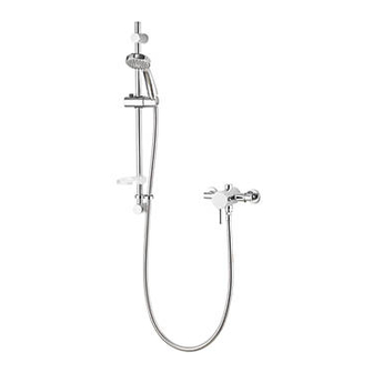
Exposed sequential valve with adjustable kit
Hide thumbs
Also See for SIERRA:
- Installation and user manual (20 pages) ,
- Installation and user manual (16 pages)

Related Manuals for Aqualisa SIERRA


Summary of Contents for Aqualisa SIERRA
- Page 1 SIERRA EXPOSED SEQUENTIAL VALVE WITH ADJUSTABLE KIT INSTALLATION AND USER GUIDE...
-
Page 2: Table Of Contents
CONTENTS General Information Tools Required (Tools not supplied) Warranty Before You Start Flow Regulators Installation Fitting the Shower Kit Cartridge Temperature Adjustment Cleaning the Thermostatic Cartridge User Instructions General Cleaning Trouble Shooting GENERAL INFORMATION This product complies with EN1111. This product must be fitted in compliance with the UK Water Supply (Fittings) Regulations. -
Page 3: Tools Required (Tools Not Supplied)
In addition if you require replacement parts please contact the Aqualisa customer helpline on 01959 560010 for assistance. WARRANTY Aqualisa products are supplied complete with a 1 year guarantee that can be upgraded by registering this product with Aqualisa. For details see: www.aqualisa.co.uk/warranty... - Page 4 WATER SUPPLY REQUIREMENTS Hot Water Maximum: 65˚C Cold Water Minimum: 5˚C Recommended 60-65˚C Recommended 10-15˚C Always maintain a 10˚C difference between hot system temperature and maximum hot setting of valve. Operating Pressure Range: Min. 0.1 bar, Max. 5.0 bar When water pressure is higher than 5 bar a pressure reducing valve (not supplied) must be fitted before the mixer.
-
Page 5: Flow Regulators
FLOW REGULATORS This product is supplied with factory fitted flow regulators to maximise the temperature stability. Flow regulators are factory fitted to the inlet connections of the valve body; these can be removed by unscrewing the inlet elbows from the valve body. Recommendations: Mains fed/high pressure systems (e.g. - Page 6 Construct suitable 15mm inlet supplies at level 150mm centres. Ensure the pipework protrudes a minimum of 100mm, measured from the intended finished wall surface. Elbow cover plates Wall plugs Inlet water supplies Mounting bracket As viewed from front on: Copper olives Left = HOT Wall screws Right = COLD...
- Page 7 Place valve body against the wall with elbows over the pipe tails and mark around the base where it sits on the wall. Remove valve body, place mounting bracket in centre of the outlined valve *Valve position outline position* and mark points for fixing holes.
-
Page 8: Fitting The Shower Kit
Fitting the Shower Kit - Rail Assembly ADJUSTABLE SHOWER KIT DESCRIPTION Wall Plug Upper Rail Bracket Short Wall Screw End Cap Handset Holder Handset Riser Rail Soap Dish Shower Hose - 1.5m Hose Restraint Lower Rail Bracket Long Wall Screw The top bracket is a floating bracket and can be positioned to suit existing screw holes (if required). - Page 9 Fit the hose restraint to the rail followed by the soap dish and handset holder. The handset holder button must be depressed whilst fitting. The button must be to the left of the rail, and the holder to the right. Secure the upper rail bracket into position on the finished wall surface using the short wall screw.
-
Page 10: Cartridge Temperature Adjustment
CARTRIDGE TEMPERATURE ADJUSTMENT This product has been factory set under balanced pressures, and a hot water supply of 65°C. N.B. This product can reach temperatures in excess of 50°C. If site conditions vary significantly from the factory conditions, it may be necessary to adjust the maximum temperature setting of the shower. -
Page 11: Cleaning The Thermostatic Cartridge
CLEANING THE THERMOSTATIC CARTRIDGE See image page 12. 1. Before carrying out any maintenance, ensure the water supplies are isolated. Once isolated, turn the shower on to release internal pressure. If unsure contact a qualified tradesman. 2. Carefully remove the control handle cover cap by inserting a small flat bladed screwdriver into the slot (located at the 6 o'clock position) and levering out. -
Page 12: User Instructions
For cooler temperature - rotate clockwise. For warmer temperature -rotate anticlockwise N.B. With all Sierra™ shower valves fitted to combination boiler systems, it may be necessary to adjust the control lever and reduce the flow to achieve a comfortable showering temperature. -
Page 13: General Cleaning
Shower head and rail system NEVER ATTEMPT TO MAKE ANY ADJUSTMENT TO THE SHOWER HEAD BY PULLING ON THE SHOWER HOSE. 1. To select the preferred height for the shower head, depress the handset holder button to enable the slider to be moved up or down the rail. 2. -
Page 14: Trouble Shooting
TROUBLE SHOOTING Symptom Possible Cause Remedy Water leaking This is normal for a short time after Adjust angle of shower head from shower turning off. in holder as necessary to vary head. draining time. Clean shower head. Shower flow valve failing to close Remove cartridge and check. - Page 15 Symptom Possible Cause Remedy Outlet water Inlet filter is partially blocked. Check inlet filters for any blockages temperature too and clean as necessary. hot/cold. Installation conditions outside See Water Supply Requirements operating parameters. page 4. Refer to Cleaning the Thermostatic Cartridge section see page 11.
- Page 16 Please note that calls may be recorded for training and quality purposes. The company reserves the right to alter, change or modify the product specifications without prior warning. ™ Trademark of Aqualisa Products Limited. Part No: 704452 Issue 01 Aug 19...
Need help?
Do you have a question about the SIERRA and is the answer not in the manual?
Questions and answers