Sign In
Upload
Manuals
Brands
Beckhoff Manuals
Touch terminals
ELX3351
Beckhoff ELX3351 Manuals
Manuals and User Guides for Beckhoff ELX3351. We have
2
Beckhoff ELX3351 manuals available for free PDF download: Operating Manual, Documentation
Beckhoff ELX3351 Operating Manual (71 pages)
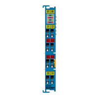
1-channel analog input terminal for strain gauge, 16 bit, Ex i
Brand:
Beckhoff
| Category:
Touch terminals
| Size: 2.69 MB
Table of Contents
Table of Contents
3
1 Foreword
5
Notes on the Documentation
5
Safety Instructions
6
Documentation Issue Status
7
Marking of ELX Terminals
8
Fig. 1 ELX1052-0000 with Date Code 32180000, BTN 10000100 and Ex Marking
9
Fig. 2 ELX9012 with Date Code 32180005 and Ex Marking
10
2 Product Overview
11
ELX3351 - Introduction
11
Fig. 3 1-Channel Analog Input Terminal for Strain Gauge, 16 Bit, Ex I
11
Technical Data
12
Intended Use
13
3 Mounting and Wiring
14
Special Conditions of Use for ELX Terminals
14
Installation Notes for ELX Terminals
14
Arrangement of ELX Terminals Within a Bus Terminal Block
16
Fig. 4 Valid Arrangement of the ELX Terminals (Right Terminal Block)
16
Fig. 5 Valid Arrangement - Terminals that Do Not Belong to the ELX Series Are Set before and after the
16
Fig. 6 Valid Arrangement - Multiple Power Supplies by ELX9560, each with an Upstream ELX9410
16
Fig. 7 Valid Arrangement - ELX9410 in Front of an ELX9560 Power Supply Terminal
17
Fig. 8 Invalid Arrangement - Missing ELX9560 Power Supply Terminal
17
Fig. 9 Invalid Arrangement - Terminal that Does Not Belong to the ELX Series Within the ELX Terminal Segment
17
Fig. 10 Invalid Arrangement - Second ELX9560 Power Supply Terminal Within the ELX Terminal Seg- Ment Without an Upstream ELX9410
17
Fig. 11 Invalid Arrangement - Missing ELX9012 Bus End Cover
18
Installation Position and Minimum Distances
19
Fig. 12 Installation Position and Minimum Distances
19
Installation of ELX Terminals on Mounting Rails
20
Fig. 13 Attaching on Mounting Rail
20
Connection
21
Connection System
21
Fig. 14 Disassembling of Terminal
21
Wiring
22
Fig. 15 Standard Wiring
22
Fig. 16 Connecting a Cable on a Terminal Point
22
Proper Line Connection
23
Shielding and Potential Separation
23
ELX3351 - Contact Assignment
24
Fig. 17 ELX3351 - Contact Assignment
24
Fig. 18 ELX3351 - Connection of a Full Bridge in 6-Wire Technology
25
4 Basic Function Principles
26
Ethercat Basics
26
Basic Principles of Strain Gauge Technology
26
Fig. 19 Strain Gauge
26
Fig. 20 Quarter, Half, and Full Bridge
27
Fig. 21 4-Wire Connection
28
Fig. 22 6-Wire Connection
28
Fig. 23 Example of a Load Cell
29
Fig. 24 Parallel Strain Gauge
31
5 Parameterization and Programming
33
Basics of the Measurement Functions
33
General Notes
33
Fig. 25 Max. Input Voltages
33
Fig. 26 Parallel Connection with ELX3351
34
Block Diagram
35
Software Filter
35
Fig. 27 ELX3351 - Block Diagramm
35
Fig. 28 Notch Characteristic/Amplitude Curve and Step Response of the FIR Filter
35
Fig. 29 Step Response of the IIR Filter
36
Dynamic Filter
37
Fig. 30 Effect of Dynamic IIR Filters
37
Calculating the Weight
38
Application Notes
38
Wiring Fail Indication
38
Inputfreeze
38
Gravity Adaptation
39
Fig. 31 Inputfreeze Example
39
Idling Recognition
40
Official Calibration Capability
40
Calibration and Compensation
40
Fig. 32 Idling Recognition Example
40
Sensor Calibration
41
Fig. 33 Adaptation to the Sensor Curve
41
Fig. 34 Zero Calibration with Command 0X0101 in Coe Object 0Xfb00:01
42
Fig. 35 Loading with Reference Load, Command 0X0102 in Coe Object 0Xfb00:01
42
Self-Calibration
43
Taring
44
Overview of Commands
44
Fig. 36 Control Word, Tare
44
Notices on Analog Specifications
45
Full Scale Value (FSV)
45
Measuring Error/ Measurement Deviation
45
Fig. 37 Full Scale Value, Measuring Span
45
Temperature Coefficient Tk [Ppm/K]
46
Single-Ended/Differential Typification
47
Fig. 38 SE and DIFF Module as 2-Channel Version
47
Fig. 39 2-Wire Connection
49
Common-Mode Voltage and Reference Ground (Based on Differential Inputs)
50
Dielectric Strength
50
Fig. 40 Common-Mode Voltage (VCM)
50
Temporal Aspects of Analog/Digital Conversion
51
Fig. 41 Recommended Operating Voltage Range
51
Process Data
54
Selection of Process Data
54
Default Process Image
55
Variants Predefined PDO
57
Sync Manager
58
ELX3351 - Object Description and Parameterization
59
Restore Object
59
Configuration Data
60
Command Object
61
Input Data
61
Output Data
61
Information / Diagnostic Data
62
Standard Objects
62
6 Appendix
68
Ethercat al Status Codes
68
UL Notice
68
Support and Service
69
Table of Figures
70
Advertisement
Beckhoff ELX3351 Documentation (29 pages)
Connection diagrams, EX markings and technical data for explosion protection
Brand:
Beckhoff
| Category:
DC Drives
| Size: 0.85 MB
Table of Contents
Table of Contents
3
1 Foreword
5
Notes on the Documentation
5
Safety Instructions
6
Documentation Issue Status
7
2 Connection Diagramms
8
Terminals with Digital Inputs
8
Elx1052
8
Elx1054
9
Terminals with Digital Outputs
10
Elx2002
10
Terminals with Analog Inputs
11
Elx3152
11
Elx3181
13
Elx3202
14
Elx3204
17
Elx3312
18
Elx3314
19
Elx3351
20
Terminals with Analog Outputs
22
Elx4181
22
Terminals for Position Measurement
23
Elx5151
23
3 Ex Markings
24
4 Technical Data for Explosion Protection
27
5 Appendix
28
Ethercat al Status Codes
28
Specific Condition of Use
28
Support and Service
29
Advertisement
Related Products
Beckhoff ELX3202
Beckhoff ELX3204
Beckhoff ELX3252
Beckhoff ELX3158
Beckhoff ELX3152-0000
Beckhoff ELX3158-0000
Beckhoff ELX4154
Beckhoff ELX2008-0000
Beckhoff ELX2792
Beckhoff ELX9012
Beckhoff Categories
Touch terminals
Industrial PC
Control Unit
Touch Panel
Power Supply
More Beckhoff Manuals
Login
Sign In
OR
Sign in with Facebook
Sign in with Google
Upload manual
Upload from disk
Upload from URL