Table of Contents
Advertisement
Quick Links
Installation AND MAINTENANCE INSTRUCTIONS
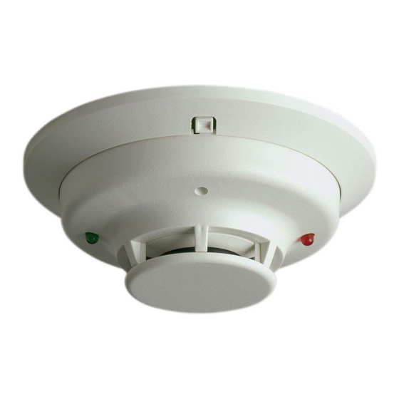
Series
Photoelectric Smoke Detector
2-Wire: C2WTR-BA (Form C Relay), C2WTA-BA (Sounder)
4-Wire: C4WTR-BA (Form C Relay), C4WTA-BA (Sounder)
C4WTAR-BA (Form C Relay, Sounder), C4WITAR-BA (Isolated Thermal, Form C Relay, Sounder)
Before Installing
Please read thoroughly System Sensor Application Guide: System Smoke De-
tectors, which provides detailed information on detector spacing, placement,
zoning, wiring, and special applications. Copies are available on System Sen-
sor's web site: www.systemsensor.ca.
NOTICE: This manual shall be left with the owner/user of this equipment.
IMPORTANT: This detector must be tested and maintained regularly follow-
ing CAN/ULC S536. At a minimum, cleaning should be performed annually.
General Description
Models C2WTR-BA and C2WTA-BA are 2-wire photoelectric smoke detectors;
models C4WTR-BA, C4WTA-BA, C4WTAR-BA, and C4WITAR-BA are 4-wire
photoelectric smoke detectors. All models incorporate a state-of-the-art optical
sensing chamber and an advanced microprocessor. The microprocessor allows
the detector to automatically adjust its sensitivity back to the factory setting
when it becomes more sensitive due to contaminants settling in its chamber.
In order for this feature to work properly, the chamber must never be opened
while power is applied to the smoke detector. This includes cleaning, main-
tenance or screen replacement. All models also feature a restorable, built-in,
fixed temperature (135°F / 57 °C) thermal detector and are also capable of
sensing a freeze condition if the temperature is below 41°F (5°C)
Models C2WTA-BA, C4WTA-BA, C4WTAR-BA, and C4WITAR-BA contain a
piezoelectric horn which generates the ANSI S3.41 temporal pattern in an
alarm condition. All detectors on a zone will sound when the power supply to
them is reversed. The CRRS-MODA can be used for the power supply reversal
function. The CRRS-MODA also enables all the detectors' sounders on a zone
to be synchronized and allows the zone to be silenced from the panel by en-
tering the alarm silence key at the keypad.
The detector that initiated the alarm condition will have its red LED and
Form C relays (if applicable) latched until reset by panel.
The model C4WITAR-BA photoelectronic smoke sensor is isolated from the
fixed-temperature heat sensor, providing a self-resetting, local audible smoke
alarm that does not alarm at the panel. Only the fixed-temperature heat sensor
will cause the C4WITAR-BA to initiate an alarm at the panel and the relay to
change its state.
NOTE: In order for all i 3 sounder detectors on a loop to sound when the panel
alarms, the supply voltage polarity must be reversed. A reversing relay, System
Sensor model number CRRS-MODA, must be used. The CRRS-MODA is de-
signed to allow all i 3 Series detectors in the same loop to sound when one of
the detectors goes into alarm. In addition, the CRRS-MODA will synchronize
all of the i 3 Series sounder smoke detectors on the loop. Some panels may
require the use of programmable outputs. Refer to System Sensor literature for
further information on the CRRS-MODA.
All i 3 Series detectors are designed to provide open area protection. Two-wire
models must be used with compatible ULC Listed panels only.
When used with an "i 3 Ready" control panel or the i 3 Series C2W-MOD2A
module (refer to installation manual), the C2WTR-BA and C2WTA-BA are ca-
pable of generating a "maintenance needed" signal. The C2W-MOD2A can
indicate a need for cleaning, replacement, or a freeze trouble at the control
panel or module.
The C2W-MOD2A has replaced the previous model number C2W-MODA. To
ensure proper remote maintenance signaling capabilities, do not use the C2W-
MODA with i 3 model numbers C2WTR-BA and C2WTA-BA.
Installation of the C2WTR-BA, C2WTA-BA, C4WTR-BA, C4WTA-BA, C4WTAR-
BA, and C4WITAR-BA detectors is simplified by the use of a mounting base
WARNING
that may be pre-wired to the system, allowing the detector to be easily in-
stalled or removed. The mounting base installation is further simplified by the
incorporation of features compatible with drywall fasteners.
Two LEDs on the detector provide a local visual indication of the detector's
status:
Table 1: Detector LED Modes
Power-up
Normal (standby)
Out of sensitivity
Freeqe Trouble
Alarm
During an initial power-up delay, the red and green LEDs will blink synchronously once
every ten seconds. It will take approximately 80 seconds for the detector to finish the
power-up cycle (see Table 2).
Table 2: Power-up Sequence for LED Status Indication*
Condition
Initial LED Status Indication
Initial LED Status Indication
(if excessive electrical noise is present)
*Refer to Electrical Specifications for start-up time in conjuction with panel alarm veri-
fication.
NOTE: If, during power-up, the detector determines there is excessive electri-
cal noise in the system such as those caused by improper grounding of the
system or the conduit, both LEDs will blink for up to 4 minutes before display-
ing detector status (see Table 2).
After power-up has completed and the detector is functioning normally within
its listed sensitivity range, the green LED blinks once every five seconds. If the
detector is in need of maintenance because its sensitivity has shifted outside
the listed limits, the red LED blinks once every five seconds. When the detec-
tor is in the alarm mode, the red LED latches on. The LED indication must not
be used in lieu of the tests specified under Testing. In a freeze trouble condi-
tion, the red LED will blink once every 10 seconds (refer to Table 1).
To measure the detector's sensitivity, the i 3 Series Model CSENS-RDRA Infra-
red Sensitivity Reader tool (see Figure 4) should be used. Refer to instructions
manual I56-2219 for the proper use of the CSENS-RDRA.
Models C2WTR-BA and C2WTA-BA also include an output that allows an op-
tional Model RA400ZA Remote Annunciator to be connected.
Mounting
General spacing guidelines are 30' × 30', with each detector covering 900 ft 2
under maximum conditions.
Consult CAN/ULC S524, the local Authority Having Jurisdiction (AHJ), and/
or applicable codes for specific information regarding the spacing and place-
ment of smoke detectors.
Each i 3 Series detector is supplied with a mounting base that can be ceiling- or
wall-mounted:
1. To a single gang box, or
1
2. To a 3
⁄
-inch or 4-inch octagonal box, or
2
3. To a 4-inch square box with a plaster ring, or
4. Direct mount or to ceiling using drywall fasteners.
1
3333 Unity Drive, Mississauga, Ontario L5L 3S6
800/736-7672, FAX: 905-812-0771
www.systemsensor.ca
Green LED
Red LED
Blink 10 sec
Blink 10 sec
Blink 5 sec
—
—
Blink 5 sec
—
Blink 10 sec
—
Solid
Duration
80 seconds
4 minutes
I56-2431-004
7/2/2019
Advertisement
Table of Contents

Related Manuals for System Sensor i3 Series


Summary of Contents for System Sensor i3 Series
- Page 1 3 Series sounder smoke detectors on the loop. Some panels may manual I56-2219 for the proper use of the CSENS-RDRA. require the use of programmable outputs. Refer to System Sensor literature for Models C2WTR-BA and C2WTA-BA also include an output that allows an op- further information on the CRRS-MODA.
- Page 2 (Figure 2), and then install the detector. To remove the detector from the base require the use of programmable outputs. Refer to System Sensor literature for once it has been made tamper resistant, use a small screwdriver to depress the further information on the CRRS-MODA.
- Page 3 The EZ Walk loop test verifies the initiating loop wiring and performed and the system will be temporarily out of service. Disable the zone provides visual status indication at each detector. Refer to System Sensor lit- or system undergoing maintenance to prevent any unwanted alarms.
- Page 4 Please refer to insert for the Limitations of Fire Alarm Systems Three-Year Limited Warranty System Sensor warrants its enclosed smoke detector to be free from defects and Nagel, 6335 Edwards Blvd., Mississauga, Ontario L5N 2W7, RA in materials and workmanship under normal use and service for a period #__________.
Need help?
Do you have a question about the i3 Series and is the answer not in the manual?
Questions and answers