Table of Contents
Advertisement
Quick Links
INSTALLATION AND MAINTENANCE INSTRUCTIONS
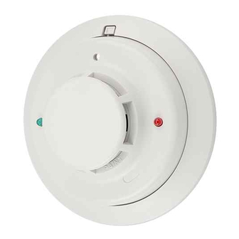
2100 and 2100T Photoelectronic
Smoke Detectors
Specifications
Diameter:
Height (including mounting bracket):
Weight:
Operating Temperature Range:
Operating Humidity Range:
Latching Alarm:
Heat Sensor (Model 2100T only):
Electrical Ratings
System Voltage
Maximum Ripple Voltage:
Start-up Capacitance:
Standby Current:
Alarm Ratings:
(Alarm current must be limited to 100 mA maximum by the control panel. If used, the RA400Z Remote Annunciator oper-
ates within the specified detector alarm currents.)
Reset Voltage:
Reset Time:
Start-up Time:
Before Installing
Please thoroughly read System Sensor manual I56-407,
Guide for Proper Use of System Smoke Detectors, which pro-
vides detailed information on detector spacing, placement,
zoning, wiring, and special applications. Copies of this
manual are available at no charge from System Sensor.
NOTICE: This manual should be left with the owner/user
of this equipment.
IMPORTANT: This detector must be tested and maintained
regularly following NFPA 72 requirements. The detector
should be cleaned at least once a year.
General Description
Model 2100 is a 2-wire photoelectronic smoke detector that
uses a state-of-the-art optical sensing chamber. This detec-
tor is designed to provide open area protection and to be
used with compatible UL-listed panels only. Model 2100T
features a restorable, built-in, fixed-temperature (135° F)
thermal detector.
D200-54-00
5.5 inches (140 mm)
1.7 inches (43 mm)
5.3 oz. (150 g)
Model 2100:
32° to 120° F (0° to 50° C)
Model 2100T:
32° to 100°F (0° to 39° C)
10% to 93% Relative Humidity, Noncondensing
Reset by momentary power interruption
135°F Fixed Temperature Electronic Thermistor
Nominal:
12 or 24 VDC
Minimum:
8.5 VDC
Maximum:
35 VDC
30% of nom. Voltage (peak to peak)
0.02 µ F maximum
50 µ A maximum
4.2 VDC minimum at 10 mA.
6.6 VDC maximum at 100 mA.
2.5 VDC minimum
0.3 seconds maximum
30 seconds maximum (after 60 second reset)
Installation of these detectors is simplified by the use of a
mounting bracket and a plug-in screw terminal block that
can be prewired to the system, allowing the detector to be
easily installed or removed for cleaning. The detector's sen-
sitivity can be tested in place using the MOD400R Test
Module. An LED on the detector provides a local visual in-
dication of the detector's status. If power is applied to the
detector, and it is functioning normally in standby, the sta-
tus LED blinks every ten seconds. The LED also latches on
in alarm.
Models 2100 and 2100T feature a visual indication that
maintenance is required – if the sensing chamber drifts out
of its sensitivity limits, the LED ceases to blink.
The detectors also include an output that allows an op-
tional Model RA400Z Remote Annunciator to be connected.
1
A Division of Pittway
3825 Ohio Avenue, St. Charles, Illinois 60174
1-800-SENSOR2, FAX: 630-377-6495
I56-710-05
Advertisement
Table of Contents

Related Manuals for System Sensor 2100


Summary of Contents for System Sensor 2100
- Page 1 IMPORTANT: This detector must be tested and maintained regularly following NFPA 72 requirements. The detector Models 2100 and 2100T feature a visual indication that should be cleaned at least once a year. maintenance is required – if the sensing chamber drifts out of its sensitivity limits, the LED ceases to blink.
- Page 2 Mounting Each 2100 and 2100T detector is supplied with a mounting System Sensor smoke detectors are marked with a compat- bracket that permits the detector to be mounted: ibility identifier located as the last digit of a five digit code 1.
- Page 3 Figure 3. Wiring diagram for the 2100 and 2100T detector: EOL RESISTOR INITIATING SPECIFIED BY PANEL LOOP MANUFACTURER – UL LISTED – – COMPATIBLE CONTROL PANEL RA400Z RA400Z REMOTE REMOTE ANNUNCIATOR ANNUNCIATOR OPTIONAL CLASS A WIRING A78-2331-01 B. Test Module (System Sensor Model No. MOD400R).
- Page 4 NFPA 72 or at least once a year. Three-Year Limited Warranty System Sensor warrants its enclosed smoke detector to be free from de- ment, RA #__________, 3825 Ohio Avenue, St. Charles, IL 60174. Please fects in materials and workmanship under normal use and service for a include a note describing the malfunction and suspected cause of failure.
Need help?
Do you have a question about the 2100 and is the answer not in the manual?
Questions and answers