Nibe VVM 500 Installer Manual
Indoor module
Hide thumbs
Also See for VVM 500:
- Installer manual (80 pages) ,
- User manual (72 pages) ,
- Service manual (56 pages)
Table of Contents
Advertisement
Quick Links
Advertisement
Table of Contents

Related Manuals for Nibe VVM 500


Summary of Contents for Nibe VVM 500
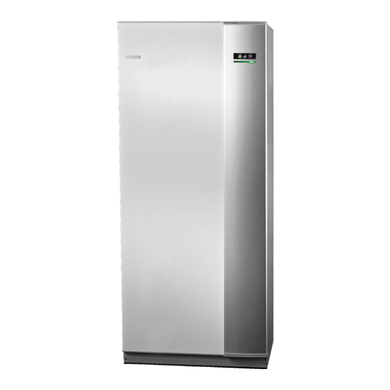
- Page 1 Installer manual NIBE™ VVM 500 Indoor module IHB GB 1212-1 031991...
- Page 2 A detailed explanation of the button functions can be found on page 27. How to scroll through menus and make different settings is described on page 29. The mode for setting the indoor temperature is reached, when in the start mode in the main menu, by pressing the OK button twice.
-
Page 3: Table Of Contents
11 Accessories 5 Electrical connections 12 Technical data General Dimensions and setting-out coordinates Connections Hot water capacity Settings Technical specifications Optional connections Electrical circuit diagram Connecting accessories Item register 6 Commissioning and adjusting NIBE™ VVM 500 Table of Contents |... -
Page 4: Important Information
Marking VVM 500 is CE marked and fulfils IP21. The CE marking means that NIBE ensures that the product meets all regulations that are placed on it based on relev- ant EU directives. The CE mark is obligatory for most products sold in the EU, regardless where they are made. - Page 5 Mixing valve Electricity (page 16) Connected communication Circuit fuses Fuses, indoor module Fuses property Outside sensor Room sensor Current sensor Safety breaker Earth circuit-breaker Setting of emergency mode thermostat Miscellaneous Docked to NIBE™ VVM 500 Chapter 1 | Important information...
- Page 6 Tel: +43 (0)7662 8963-0 Fax: +43 (0)7662 8963-44 E-mail: mail@knv.at www.knv.at NIBE Wärmetechnik AG, Winterthurerstrasse 710, CH-8247 Flurlingen Tel: (52) 647 00 30 Fax: (52) 647 00 31 E-mail: info@nibe.ch www.nibe.ch Druzstevni zavody Drazice s.r.o, Drazice 69, CZ - 294 71 Benatky nad Jizerou Tel: +420 326 373 801 Fax: +420 326 373 803 E-mail: nibe@nibe.cz www.nibe.cz...
-
Page 7: Delivery And Handling
Leave a space of 500 mm in front of the product. All VVM 500 should be transported and stored vertically in service on VVM 500 can be carried out from the front. a dry place. The VVM 500 may, however, be carefully laid on its back when being moved into a building. -
Page 8: Supplied Components
Supplied components Outside sensor Room sensor Current sensor O-rings Location The kit of supplied items is placed on top of the product. Chapter 2 | Delivery and handling NIBE™ VVM 500... -
Page 9: Removing The Covers
1. Remove the screws from the upper and lower edges. 2. Twist the cover slightly outward. 3. Move the cover backwards and slightly to the side. 4. Pull the cover to one side. 5. Pull the cover forwards. NIBE™ VVM 500 Chapter 2 | Delivery and handling... -
Page 10: Indoor Module's Design
3 Indoor module's design VVM 500 VVM 500 Chapter 3 | Indoor module's design NIBE™ VVM 500... - Page 11 Extra relay circuit board EB 1 Immersion heater FA 1 Miniature circuit-breaker FD 1 Temperature limiter SF 1 Switch Miscellaneous PF 1 Rating plate PF 3 Serial number plate Cable gland Cable gland NIBE™ VVM 500 Chapter 3 | Indoor module's design...
-
Page 12: Pipe Connections
System diagram The system requires a low-temperature design of the ra- VVM 500 consists of a hot water coil, immersion heater, diator circuit. At lowest dimensioned outdoor temperature circulation pumps, buffer vessel, control system and is (DUT) the highest recommended temperatures are 55 °C... -
Page 13: Dimensions And Pipe Connections
XL2 Heating medium, return line Ø int. XL3 Cold water Ø int. XL4 Hot water Ø int. XL8 Docking connection, flow line Ø int. XL9 Docking connection, return line Ø int. NIBE™ VVM 500 Chapter 4 | Pipe connections... - Page 14 EB 100 F20XX/F2300 QN 11 Shunt valve EM 1 Oil, gas, or electric boiler QN 19 Three way valve, pool EP 5 Exchanger, pool RM X Non-return valve EP 8 Solar panel Chapter 4 | Pipe connections NIBE™ VVM 500...
-
Page 15: Heat Pump
For connection to solar installation, the SCA 30 accessory least 19mm thick pipe insulation. is required, see "Accessories" on page 53. VVM 500 is not equipped with shut off valves; these must -FL2 -CM1 be installed outside the indoor module to facilitate any future servicing. -
Page 16: Cold And Hot Water
-EP21 fitted, or a thermostat must be removed to ensure suffi- -AA5 -BT2 -GP20 cient flow. -BT3 -QN11 -FL2 -FL2 -CM1 -CM1 -EB15 -EB15 Chapter 4 | Pipe connections NIBE™ VVM 500... -
Page 17: Installation Alternative
Connecting hot water circulation Installation alternative To reduce the risk of bacterial growth in systems with VVM 500 can be connected in several different ways, hot water circulation, the temperature of the circulating some of which are shown below. water should not fall below 50 °C. There should not be Further option information is available at www.nibe.eu... -
Page 18: Electrical Connections
Disconnect the indoor module before insulation test- ing the house wiring. If the building is equipped with an earth-fault breaker, VVM 500 should be equipped with a separate one. For the indoor module wiring diagram, see page 58. Communication and sensor cables to external connec- tions must not be laid close to high current cables. - Page 19 2. Angle out the cover and remove it. Removing the cover, immersion heater circuit board VVM 500 1. Insert the screwdriver (A) and pry the catch carefully downwards (B). 2. Angle out the cover and remove it. NIBE™ VVM 500 Chapter 5 | Electrical connections...
-
Page 20: Connections
If a conduit is used it must be sealed to prevent condens- ation in the sensor capsule. Power connection VVM 500 must be installed via an isolator switch with a minimum breaking gap of 3mm. Minimum cable area must be dimensioned according to the fuse rating used. - Page 21 Communication If VVM 500 is to be connected to the heat pump, it is connected to terminals X4:13, X4:14 and X4:15 on the input card (AA3). NIBE™ VVM 500...
-
Page 22: Settings
NOTE Switch (SF1) must not be moved to " " or " " until VVM 500 has been filled with water. Oth- erwise the temperature limiter, thermostat and the immersion heater etc can be damaged. Electrical addition - maximum output... -
Page 23: Optional Connections
Optional connections to the correct connection in the software in VVM 500. Load monitor Caution When many power consumers are connected in the If an external switch function or sensor is connec-... - Page 24 If any of the above is installed to terminal block X7 it must be selected in menu 5.4, see page 46. The common alarm is preselected at the factory. Chapter 5 | Electrical connections NIBE™ VVM 500...
-
Page 25: Connecting Accessories
Connecting accessories Instructions for connecting accessories are provided in the manual accompanying the accessory. See page 53 for the list of the accessories that can be used with VVM 500. NIBE™ VVM 500 Chapter 5 | Electrical connections... -
Page 26: Commissioning And Adjusting
(FD1) has not deployed. VVM 500 Caution Check the temperature limiter (FD1) and mini- ature circuit-breaker (FA1) in VVM 500. They may have tripped during transportation. Filling and venting Filling the hot water coil 1. Open a hot water tap in the house. -
Page 27: Start-Up And Inspection
As long as the start guide is active, no function in the installation will start automatically. The guide will appear at each installation restart until it is deselected on the last page. Operation in the start guide NIBE™ VVM 500 Chapter 6 | Commissioning and adjusting... - Page 28 Air is initially released from the hot water and venting may be necessary. If gurgling sounds can be heard from Both the circulation pumps in VVM 500 are frequency the climate system, the entire system will require addition- controlled and set themselves using control and external al venting.
-
Page 29: Control - Introduction
The control knob can be turned to the right or left. You can: scroll in menus and between options. increase and decrease the values. change page in multiple page instructions (for example help text and service info). NIBE™ VVM 500 Chapter 7 | Control - Introduction... -
Page 30: Menu System
See page 39. Menu 5 - SERVICE Advanced settings. These settings are not available to the end user. The menu is visible by pressing the Back button for 7 seconds. See page 43. Chapter 7 | Control - Introduction NIBE™ VVM 500... - Page 31 To select another option: 1. Mark the applicable option. One of the options is pre-selected (white). 2. Press the OK button to confirm the selected op- tion. The selected option has a green tick. NIBE™ VVM 500 Chapter 7 | Control - Introduction...
- Page 32 1. Use the control knob to select the help symbol. 2. Press the OK button. The help text often consists of several windows that you can scroll between using the control knob. Chapter 7 | Control - Introduction NIBE™ VVM 500...
-
Page 33: Control - Menus
Without an activated room sensor the desired change is heating whilst radiators may require three. set (of setting in menu 1.1). A one degree change in room temperature requires one increment for underfloor NIBE™ VVM 500 Chapter 8 | Control - Menus... - Page 34 You can select heating curve and read off how the flow line temperature changes at different outdoor temperatures here. Chapter 8 | Control - Menus NIBE™ VVM 500...
- Page 35 +2 steps increases the 1.9.7) is used. supply temperature by 5 °C at all outdoor temperatures. 5. Press the OK button to exit the setting. NIBE™ VVM 500 Chapter 8 | Control - Menus...
- Page 36 Set the minimum temperature on the supply temperature 1. Turn the control knob so that the ring on the shaft to the climate system. This means that VVM 500 never with the outdoor temperature is marked. calculates a temperature lower than that set here.
- Page 37 "outdoor temp. point" is set to "-2" and "change in curve" is increased until the desired room temperature is maintained. Caution Wait 24 hours before making a new setting, so that the room temperature has time to stabilise. NIBE™ VVM 500 Chapter 8 | Control - Menus...
-
Page 38: Menu 2 - Hot Water
OK button. The time to the right displays the remaining time at the selected setting. When the time has run out VVM 500 returns to the mode set in menu 2.2. Select “off" to switch off... - Page 39 "operating time" decide how long the hot water circula- tion pump must run per operating instance. "downtime" decide how long the hot water circulation pump must be stationary between operating instances. NIBE™ VVM 500 Chapter 8 | Control - Menus...
-
Page 40: Menu 3 - Info
Information about the additional heat settings, operating status and statistics can be obtained here. No changes can be made. The information is on several pages. Turn the control knob to scroll between the pages. Chapter 8 | Control - Menus NIBE™ VVM 500... -
Page 41: Menu 4 - My System
Status information for the relevant menu can be found temperature and there is no hot water or heating require- on the display to the right of the menus. ment, VVM 500 starts pool heating. plus functions Settings applying to any installed extra Untick "activated"... - Page 42 You can select what icon should be visible when the door The indoor module operating mode is usually set to to VVM 500 is closed. You can select up to 3 icons. If "auto". It is also possible to set the indoor module to you select more, the ones you selected first will disappear.
- Page 43 Setting range: -1000 – -30 Default value: -60 start addition Setting range: -2000 – -30 Default value: -700 diff. between additional steps Setting range: 0 – 1000 Default value: 100 NIBE™ VVM 500 Chapter 8 | Control - Menus...
- Page 44 Blocking: The desired blocking is selected here. Blocking the compressor. Blocking additional heat. If you wish to set similar scheduling for every day of the week start by filling in “all” and then changing the desired days. Chapter 8 | Control - Menus NIBE™ VVM 500...
-
Page 45: Menu 5 - Service
Setting software controlled in and out- puts on the input circuit board (AA3). factory setting service Total reset of all settings (including settings available to the user ) to default values. NIBE™ VVM 500 Chapter 8 | Control - Menus... - Page 46 If the installation has more than one climate system, individual maximum flow temperatures can be auto: The heating medium pump runs according to the set for each system. current operating mode for VVM 500. continuous: Continuous operation. Caution Menu 5.1.11 - pump speed heating medium...
- Page 47 Default values: 16 A EB101 setting A4 Here you set the max. electrical output of the internal electrical addition in VVM 500 and the fuse size for the Default value: 20 minutes installation. setting A7 The results of these checks appear just below where the Default value: -20 °C...
- Page 48 Mark “search installed acc." and press the OK button to solar tank and production of steam in the solar circuit. automatically find connected accessories for VVM 500. anti-freeze temperature: Here you can set the temper- Menu 5.3 - accessory settings ature in the solar panel at which the circulation pump is to start to prevent freezing.
- Page 49 A counter at the bottom shows the number of days the function has been active. NOTE During floor drying the heating medium pump in 100% runs regardless of the setting in menu 5.1.10. NIBE™ VVM 500 Chapter 8 | Control - Menus...
-
Page 50: Service
NOTE (°C) (kOhm) Servicing should only be carried out by persons 351.0 3.256 with the necessary expertise. 251.6 3.240 When replacing components on VVM 500 only 182.5 3.218 replacement parts from NIBE may be used. 133.8 3.189 99.22 3.150 74.32 3.105... - Page 51 VVM 500 from NIBE. The fact box at the top of the display shows information VVM 500 is equipped with a USB socket in the display (always in English) of the most probable update that the unit. This USB socket can be used to connect a USB update software has selected form the USB memory.
- Page 52 1. Set the desired interval between loggings. 2. Tick “activated". 3. Mark “read log settings" and press the OK button. 4. The present values from VVM 500 are saved in a file in the USB memory at the set interval until “activ- ated" is unticked.
-
Page 53: Disturbances In Comfort
Enter menu 1.3.4 and select “Off”. running. In this case the immersion heater produces heat External switch for changing the room heating activ- and/or hot water. ated. NIBE™ VVM 500 Chapter 10 | Disturbances in comfort... - Page 54 Wait until the temperature condition has been reset. Minimum time between compressor starts has not been reached. Wait 30 minutes and check if the compressor has started. Alarm tripped. Follow the display instructions. Chapter 10 | Disturbances in comfort NIBE™ VVM 500...
-
Page 55: Accessories
App” can be used with a mobile telephone with the An- Part no. 067 064 droid operating system . SCA 30 Part no. 067 073 SCA 30 means that VVM 500 can be connected to solar Energy measurement kit EMK 500 heating. Part no. 067 178 Part no. 067 179... -
Page 56: Technical Data
12 Technical data Dimensions and setting-out coordinates 25-50 Chapter 12 | Technical data NIBE™ VVM 500... -
Page 57: Hot Water Capacity
Hot water capacity (l/min) NIBE™ VVM 500 Chapter 12 | Technical data... -
Page 58: Technical Specifications
Max system pressure heating medium 0.3 (3 bar) Min flow Max HM temp °C Pipe connections Heating medium, CU pipe int. Hot water connection int. Cold water connection int. Heat pump connections int. Chapter 12 | Technical data NIBE™ VVM 500... - Page 59 Height 1900 Required ceiling height 2000 Weight (excl packaging) Part no. 069 400 RSK No. 624 23 28 Applies with an outdoor air heat pump at 7/45 °C (outdoor temperature/flow line temperature) NIBE™ VVM 500 Chapter 12 | Technical data...
-
Page 60: Electrical Circuit Diagram
Electrical circuit diagram Chapter 12 | Technical data NIBE™ VVM 500... - Page 61 NIBE™ VVM 500 Chapter 12 | Technical data...
- Page 62 Chapter 12 | Technical data NIBE™ VVM 500...
- Page 63 NIBE™ VVM 500 Chapter 12 | Technical data...
- Page 64 Chapter 12 | Technical data NIBE™ VVM 500...
-
Page 65: Item Register
Power steps of the immersion heater, 20 Scroll through the windows, 30 Electrical circuit diagram, 58 Selecting menu, 29 Electrical connections, 16 Selecting options, 29 Accessibility, electrical connection, 17 Setting a value, 29 NIBE™ VVM 500 Chapter 13 | Item register... - Page 66 Removing the hatch, input circuit board, 17 Transport, 5 Room sensor, 19 Troubleshooting, 51 Safety information, 2 USB service outlet, 49 Contact information, 4 Inspection of the installation, 3 Marking, 2 Venting the climate system, 24 Chapter 13 | Item register NIBE™ VVM 500...
- Page 68 NIBE AB Sweden Hannabadsvägen 5 Box 14 SE-285 21 Markaryd info@nibe.se www.nibe.eu 031991...
Need help?
Do you have a question about the VVM 500 and is the answer not in the manual?
Questions and answers