Nibe VVM 320 Installer Manual
Indoor module
Hide thumbs
Also See for VVM 320:
- User manual (93 pages) ,
- Technical manual (88 pages) ,
- Installer manual (88 pages)
Table of Contents
Advertisement
Quick Links
Advertisement
Table of Contents

Related Manuals for Nibe VVM 320


Summary of Contents for Nibe VVM 320
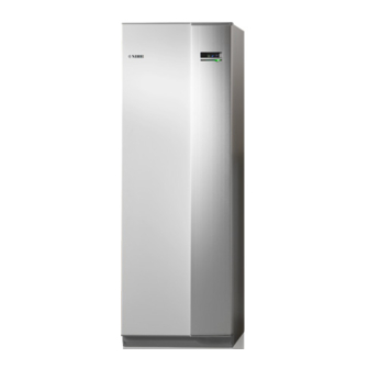
- Page 1 Installer manual NIBE™ VVM 320 Indoor module IHB GB 1613-5 231357...
- Page 2 Quick guide Navigation Ok button (confirm/select) Back button (back/undo/exit) Control knob (move/increase/reduce) A detailed explanation of the button functions can be found on page 40. How to scroll through menus and make different settings is described on page 41. Set the indoor climate INDOOR CLIMATE HOT WATER MY INSTALLATION...
-
Page 3: Table Of Contents
Electrical circuit diagram, 3 x 400V Filling and venting Electrical circuit diagram, 3 x 230V Start-up and inspection Electrical circuit diagram, 1 x 230V Setting the cooling/heating curve Index Setting hot water circulation Pool SG Ready NIBE™ VVM 320 Table of Contents |... -
Page 4: Important Information
This symbol indicates tips on how to facilitate using the product. Marking VVM 320 is CE marked and fulfils IP21. The CE marking means that NIBE ensures that the product meets all regulations that are placed on it based on relevant EU directives. The CE mark is obligat- ory for most products sold in the EU, regardless where they are made. - Page 5 Safety valve Electricity (page 23) Connected communication Circuit fuses Fuses, indoor module Fuses property Outside sensor Room sensor Current sensor Safety breaker Earth circuit-breaker Setting of emergency mode thermostat Miscellaneous Docked to NIBE™ VVM 320 Chapter 1 | Important information...
- Page 6 NIBE Energy Systems France Sarl, Zone industrielle RD 28, Rue du Pou du Ciel, 01600 Reyrieux Tel : 04 74 00 92 92 Fax : 04 74 00 42 00 E-mail: info@nibe.fr www.nibe.fr NIBE Energy Systems Ltd, 3C Broom Business Park, Bridge Way, Chesterfield S41 9QG Tel: 0845 095 1200 Fax: 0845 095 1201 E-mail: info@nibe.co.uk www.nibe.co.uk...
-
Page 7: Delivery And Handling
2 Delivery and handling Transport Supplied components 40 mm VVM 320 should be transported and stored vertically in a dry place. However, the VVM 320 may be carefully laid on its back when being moved into a building. Assembly Outside sensor Room sensor Position VVM 320 on a solid foundation that tolerates ■... -
Page 8: Removing The Covers
1. Remove the screws from the upper and lower edges. 2. Twist the cover slightly outward. 3. Move the hatch backwards and slightly to the side. 4. Pull the cover to one side. 5. Pull the hatch forwards. Chapter 2 | Delivery and handling NIBE™ VVM 320... -
Page 9: Indoor Module's Design
3 Indoor module's design VVM 320 W130 AA4-XJ3 AA4-XJ4 VVM320 QM11 VVM320 QM22 QN10 BT63 BT30 AA1-S2 QM20 NIBE™ VVM 320 Chapter 3 | Indoor module's design... - Page 10 Safety valve, water heater Safety valve, heating medium 1) Not Denmark and Germany. 2) Applies to VVM 320 R, VVM 320 3x230V R and VVM 320 E EM. Available as accessory EMK 300 for other markets. Chapter 3 | Indoor module's design...
-
Page 11: Pipe Connections
55 °C on the supply line and 45 °C on the return line, but VVM 320 can handle up to 65 °C. Overflow water from the safety valve goes via overflow cups to a drain so that hot water splashes cannot cause injury. -
Page 12: Dimensions And Pipe Connections
System diagram Symbol Meaning VVM 320 consists of water heater with charge coil, ex- VVM320 Under floor heating systems pansion vessel, safety valve, filler valve, immersion heater, circulation pumps, buffer vessel and control system. VVM 320 is connected to the climate system. - Page 13 Connection, cold water Ø22 mm Connection, hot water Ø22 mm Connection, hot water circulation Ø15 mm (does not apply to copper) Connection, docking in heating medium Ø22 Connection, docking out heating medium Ø22 NIBE™ VVM 320 Chapter 4 | Pipe connections...
-
Page 14: Installation Alternative
F2120-12 all versions F2120-16 all versions VVM 320 can be connected to extra water heater, see below. Further option information is available at www.nibe.eu and in the respective assembly instructions for the ac- cessories used. See page 61 for a list of the accessories that can be used with VVM 320. - Page 15 External electrical additional heat External heat source (Oil, gas, pellets or wood 1) Energy meter (BF1) is included in VVM 320 R, VVM 320 3x230V fired boiler with shunt valve) R and VVM 320 E EM. Available as accessory EMK 300 for other markets.
- Page 16 Outline diagram -CL11 -EP5 -BT51 -GP9 -HQ4 POOL -AA25 -EP21 -AA25 -BT2 -GP20 -BT3 -QN25 -CL11 -GP12 -CL11 -QN19 -EB15 -EB101 -EB101 -QM41 -XL1 -QM40 -HQ1 -XL2 -FL10 Chapter 4 | Pipe connections NIBE™ VVM 320...
- Page 17 20 mm thick pipe insulation. radiators/underfloor heating coils, a relief valve must be fitted, or a thermostat must be removed to ensure VVM 320 is not equipped with shut off valves; these sufficient flow. must be installed outside the indoor module to facilit- ate any future servicing.
- Page 18 The electrical addition should not be greater than the heat pump's power, just before being stationary. -XL8 -XL9 -EB15 -EB1 -EB101 -EB101 -QM41 -XL1 -QM40 -HQ1 -XL2 -FL10 Chapter 4 | Pipe connections NIBE™ VVM 320...
- Page 19 The POOL 310 accessory is required for this connection. -CL11 -EP5 -BT51 -GP9 -HQ4 POOL -AA25 -CL11 -GP12 -CL11 -QN19 -XL8 -XL9 -EB15 -EB101 -EB101 -QM41 -XL1 -QM40 -HQ1 -XL2 -FL10 NIBE™ VVM 320 Chapter 4 | Pipe connections...
- Page 20 The demand on F135 is controlled by the indoor module in the system. The pump and fan speed are also controlled from the menu in the indoor module. -AZ10 -AZ10 -HQ1 -GP10 -QM42 -QM43 -XL8 -RM1 -XL9 -EB15 -EB101 -EB101 -QM41 -XL1 -QM40 -HQ1 -XL2 -FL10 Chapter 4 | Pipe connections NIBE™ VVM 320...
- Page 21 POOL -AA25 -AZ10 -AZ10 -HQ1 -GP10 -QM42 -QM43 -CL11 -GP12 -QM44 -CL11 -EQ1 -QN19 -XL8 -AA25 -GP13 -RM1 -XL9 -EB15 -CP10 -GP12 -BT64 -QN12 -EB101 -EB101 -QM41 -XL1 -QM40 -HQ1 -XL2 -FL10 NIBE™ VVM 320 Chapter 4 | Pipe connections...
- Page 22 It is also possible to choose if the system is to use the energy source that is most CO neutral at the time. -EM1 -AA25 -EM1 -EM1 -QM43 -EM1 -EM1 -QM42 -RM1 -EB15 -EB101 -EB101 -QM41 -QM40 -HQ1 -FL10 Chapter 4 | Pipe connections NIBE™ VVM 320...
-
Page 23: Electrical Connections
■ testing the house wiring. If the building is equipped with an earth-fault ■ VVM320 breaker, VVM 320 should be equipped with a separ- ate one. For the indoor module wiring diagram, see page 67. ■ VVM320 Communication and sensor cables to external con- ■... - Page 24 1. Push the catch down. 1. Insert the screwdriver (A) and pry the catch care- fully downwards (B). 2. Angle out the cover and remove it. 2. Angle out the cover and remove it. Chapter 5 | Electrical connections NIBE™ VVM 320...
- Page 25 Cable lock Use a suitable tool to release/lock cables in the indoor module terminal blocks. NIBE™ VVM 320 Chapter 5 | Electrical connections...
-
Page 26: Connections
Power connection affected by the morning sun for example. VVM 320 must be installed via an isolator switch with Connect the sensor to terminal block X6:1 and X6:2 on the input board (AA3). Use a twin core cable of at least a minimum breaking gap of 3mm. - Page 27 Communication VVM 320 is supplied with a room sensor enclosed If VVM 320 is to be connected to the heat pump, it is (BT50). The room sensor has up to three functions: connected to terminal blocks X4:13, X4:14 and X4:15 on the input board (AA3).
-
Page 28: Settings
15.7 15.7 15.7 3x400V (maximum electrical output, connected to 7 kW) Electrical Max L1 (A) Max L2 (A) Max L3 (A) addition (kW) Chapter 5 | Electrical connections NIBE™ VVM 320... - Page 29 3x230V, that is 6 kW. Power in emergency mode, 3x230V (maximum electrical output, connected upon delivery 9 kW) The image shows the dip-switch (AA1-SF1) in the fact- ory setting for 1x230V, that is 6 kW. NIBE™ VVM 320 Chapter 5 | Electrical connections...
- Page 30 45 °C (for example För markvärme! radiators). Output locking VVM 320 follows applicable building regulations (BBR). För frånluftsvärme! This means that the maximum power output (maxim- um installed electrical output for heating) can be locked in menu 5.1.13.
-
Page 31: Optional Connections
5.4, see page 52. If an external switch function or sensor is con- External blocking of addition and compressor can be nected to VVM 320, the function to use input combined. or output must be selected in menu 5.4, see A closed contact results in the electrical output being page 52. - Page 32 NOTE "SG Ready" requires two AUX inputs. In systems with both under floor heating and radiators, NIBE ECS 40/41 should be used for In cases where this function is required it must be optimum operation. connected to terminal block 6 on the input board (3).
- Page 33 Mark up any junction boxes with warnings for external voltage. 1 2 3 C NO NC AA3-X7 F1X45 VVM 320 External Externt AA3-X7 Circulation pump Caution The relay outputs can have a max load of 2 A (230V AC). NIBE™ VVM 320 Chapter 5 | Electrical connections...
-
Page 34: Connecting Accessories
Refer to the accessory manual for further instructions. EB15 VVM320 VVM 310 AA3-X4 VVM 310 VVM 320 VVM325 VVM325 VVM 500 AA3-X4 VVM 325 VVM 500 Accessory card 1 AA5-X4 AA5-X4 -X10 Accessory card 2 AA5-X4 AA5-X4 -X10 Chapter 5 | Electrical connections NIBE™ VVM 320... -
Page 35: Commissioning And Adjusting
Filling VVM 320 1. Open the vent valve (QM20). 2. Open the filling valve (QM11). VVM 320 is filled with water. 3. When the water exiting the vent valve (QM20) is not mixed with air, close the vent valve. -
Page 36: Start-Up And Inspection
As long as the start guide is active, no function the menu number in the control system. in VVM 320 will start automatically. If you want to read more about affected menus either The guide will appear at each restart of VVM consult the help menu or read the user manual. -
Page 37: Setting The Cooling/Heating Curve
°C pump again. cooling curve 1.9.1.2 Pump speed system The circulation pump (GP1) in VVM 320 is frequency flow temperature °C controlled and sets itself using control and based on heating demand. outdoor temp. °C heating curve Setting range: 0 –... -
Page 38: Setting Hot Water Circulation
"operating time" decide how long the hot water circu- 1. Select the climate system (if more than one) for lation pump must run per operating instance. which the curve is to be changed. Chapter 6 | Commissioning and adjusting NIBE™ VVM 320... -
Page 39: Pool
With low price mode on "SG Ready", the desired pool quirement, VVM 320 starts pool heating. temperature (start and stop temperature) is increased Untick "activated" to switch off the pool heating. -
Page 40: Control - Introduction
The control knob can be turned to the right or left. You can: ■ scroll in menus and between options. ■ increase and decrease the values. ■ change page in multiple page instructions (for example help text and service info). Chapter 7 | Control - Introduction NIBE™ VVM 320... -
Page 41: Menu System
HOT WATER Hot water temp. These two symbols indicate whether the compressor in the outdoor unit or addi- tional heat is blocked in VVM 320. These can, for example, be blocked de- Information about operation pending on which operating mode is se- lected in menu 4.2, if blocking is sched-... - Page 42 (at the page number) has been marked. 2. Press the OK button to skip between the steps in the start guide. If the start guide is left on this page it closes automatically in 60 min Chapter 7 | Control - Introduction NIBE™ VVM 320...
- Page 43 1. Use the control knob to select the help symbol. 2. Press the OK button. The help text often consists of several windows that you can scroll between using the control knob. NIBE™ VVM 320 Chapter 7 | Control - Introduction...
-
Page 44: Control - Menus
1.9.5 - cooling settings * 1.9.6 - fan return time * 1.9.7 - own curve 1.9.7.1 - heating 1.9.7.2 - cooling * 1.9.8 - point offset 1.9.11 - +Adjust * Accessories are needed. Chapter 8 | Control - Menus NIBE™ VVM 320... -
Page 45: Menu 2 - Hot Water
Menu 3 - INFO 3 - INFO 3.1 - service info 3.2 - compressor info 3.3 - add. heat info 3.4 - alarm log 3.5 - indoor temp. log * Accessories are needed. NIBE™ VVM 320 Chapter 8 | Control - Menus... -
Page 46: Menu 4 - My System
Menu 4 - MY SYSTEM 4 - MY SYSTEM 4.1 - plus functions 4.1.1 - pool * 4.1.3 - internet 4.1.3.1 - NIBE Uplink 4.1.3.8 - tcp/ip settings 4.1.3.9 - proxy settings 4.1.4 - sms * 4.1.5 - SG Ready 4.1.6 - smart price adaption™... -
Page 47: Menu 5 - Service
(AA3). on the display to the right of the menus. factory setting service Total reset of all settings (includ- ing settings available to the user ) to default values. NIBE™ VVM 320 Chapter 8 | Control - Menus... - Page 48 Menu 5.1.1 - hot water settings Setting range: 1 – 25 °C Default value: 10 °C VVM 320 Stainless steel or VVM 320 Enamel max diff addition economy Setting range: 1 – 24 °C Setting range start temp. economy: 5 – 70 °C Default value: 7 °C...
- Page 49 Here you set the max. electrical output of the internal The hot water temperature (BT6) must be be- electrical addition in VVM 320 and the fuse size for the low 40 °C in order for the flow test to start.
- Page 50 VVM description. 320. Menu 5.3 - accessory settings The operating settings for accessories that are installed and activated are made in the sub-menus for this. Chapter 8 | Control - Menus NIBE™ VVM 320...
- Page 51 Setting range: on/off outgoing hot water: Set the temperature at which the mixing valve is to restrict hot water from the water Factory setting: off heater. NIBE™ VVM 320 Chapter 8 | Control - Menus...
- Page 52 Menu 5.7 - start guide When the indoor module is started for the first time the start guide starts automatically. Start it manually here. See page 36 for more information about the start guide. Chapter 8 | Control - Menus NIBE™ VVM 320...
- Page 53 During under floor drying, the heating medi- um pump in 100% runs, regardless of the set- ting in menu 5.1.10. If operating mode "add. heat only" is to be used, select it in menu 4.2. NIBE™ VVM 320 Chapter 8 | Control - Menus...
- Page 54 This option locks after 24 hours, restart of dis- here. play or program updating. auto: The heating medium pump runs according to the current operating mode for VVM 320. intermittent: The heating medium pump starts and stops 20 seconds before and after the compressor in the heat pump.
-
Page 55: Service
9 Service Service actions Venting valve (QM20) NOTE Servicing should only be carried out by persons with the necessary expertise. When replacing components on VVM 320 only replacement parts from NIBE may be used. VVM320 QM11 Emergency mode QM22 Emergency mode is used in event of operational inter- ference and in conjunction with service. - Page 56 20.02 2.673 The display unit is equipped with a USB socket that can be used to update the software, save logged informa- 15.77 2.541 tion and handle the settings in VVM 320. 12.51 2.399 10.00 2.245 INDOOR CLIMATE HOT WATER 8.045...
- Page 57 Factory setting range: 5 s plete VVM 320 restarts. Here you can choose how current measurement values NOTE from VVM 320 should be saved onto a log file on the A software update does not reset the menu USB memory. settings in VVM 320.
- Page 58 Here you can manage (save as or retrieve from) all the menu settings (user and service menus) in VVM 320 with a USB memory. Via "save settings" you save the menu settings to the USB memory in order to restore them later or to copy the settings to another VVM 320.
-
Page 59: Disturbances In Comfort
■ selected in the menu 5.1.4. (QM20), (QM32) to the climate system. ■ Closed valves to the climate system. (QM40), (QM41) to the climate system. (QM31), (QM32) to the heating system. NIBE™ VVM 320 Chapter 10 | Disturbances in comfort... - Page 60 ■ set. Minimum time between compressor starts has not ■ been reached. Wait 30 minutes and check if the compressor has ■ started. Alarm tripped. ■ Follow the display instructions. ■ Chapter 10 | Disturbances in comfort NIBE™ VVM 320...
-
Page 61: Accessories
VVM 320. Part no. 066 075 An accessory card is also required if for example an extern- al circulation pump is connected to VVM 320 at the same External electric additional heat ELK time that the buzzer alarm is activated. - Page 62 Room unit RMU 40 RMU 40 means that control and monitoring of the heat pump can be carried out in a different part of the accom- modation to where VVM 320 is located. Part no. 067 064 Solar package PV3031 3 kW Part no.
-
Page 63: Technical Data
12 Technical data Dimensions and setting-out coordinates NIBE™ VVM 320 Chapter 12 | Technical data... -
Page 64: Technical Specifications
Required ceiling height 1,910 Weight (excl. packaging and without water) Part number Copper - VVM 320 CU 069 108 Part number Stainless steel - VVM 320 R 069 109 Part number Enamel – VVM 320 E EM 069 110 Chapter 12 | Technical data NIBE™... - Page 65 Depth Height (without base) 1,800 Height (with base) 1,830 – 1,850 Required ceiling height 1,910 Weight (excl. packaging and without water) Part number Stainless steel - VVM 320 3x230V R 069 113 NIBE™ VVM 320 Chapter 12 | Technical data...
- Page 66 Depth Height (without base) 1,800 Height (with base) 1,830 – 1,850 Required ceiling height 1,910 Weight (excl. packaging and without water) Part number Stainless steel - VVM 320 1x230V R 069 111 Chapter 12 | Technical data NIBE™ VVM 320...
-
Page 67: Electrical Circuit Diagram, 3 X 400V
Electrical circuit diagram, 3 x 400V NIBE™ VVM 320 Chapter 12 | Technical data... - Page 68 Chapter 12 | Technical data NIBE™ VVM 320...
- Page 69 NIBE™ VVM 320 Chapter 12 | Technical data...
- Page 70 Chapter 12 | Technical data NIBE™ VVM 320...
- Page 71 NIBE™ VVM 320 Chapter 12 | Technical data...
-
Page 72: Electrical Circuit Diagram, 3 X 230V
Electrical circuit diagram, 3 x 230V Chapter 12 | Technical data NIBE™ VVM 320... - Page 73 NIBE™ VVM 320 Chapter 12 | Technical data...
- Page 74 Chapter 12 | Technical data NIBE™ VVM 320...
- Page 75 NIBE™ VVM 320 Chapter 12 | Technical data...
- Page 76 Chapter 12 | Technical data NIBE™ VVM 320...
-
Page 77: Electrical Circuit Diagram, 1 X 230V
Electrical circuit diagram, 1 x 230V NIBE™ VVM 320 Chapter 12 | Technical data... - Page 78 Chapter 12 | Technical data NIBE™ VVM 320...
- Page 79 NIBE™ VVM 320 Chapter 12 | Technical data...
- Page 80 Chapter 12 | Technical data NIBE™ VVM 320...
- Page 81 NIBE™ VVM 320 Chapter 12 | Technical data...
-
Page 82: Index
Draining the climate system, 35 Control - Menus, 44 Filling the hot water heater, 35 Control - Introduction, 40 Filling VVM 320, 35 Display unit, 40 Venting the climate system, 35 Menu system, 41 Filling the hot water heater, 35... - Page 83 Draining the hot water heater, 55 Standby mode, 55 Temperature sensor data, 56 USB service outlet, 56 Setting a value, 42 Setting hot water circulation, 38 Settings, 28 Emergency mode, 29 Setting the cooling/heating curve, 37 NIBE™ VVM 320 Chapter 13 | Item register...
- Page 88 WS name: -Gemensamt WS version: a172 (working edition) Publish date: 2016-04-06 06:50 NIBE AB Sweden Hannabadsvägen 5 Box 14 SE-285 21 Markaryd info@nibe.se www.nibe.eu 231357...
Need help?
Do you have a question about the VVM 320 and is the answer not in the manual?
Questions and answers