Nibe F2040 Installation Manual
Hide thumbs
Also See for F2040:
- Technical manual (116 pages) ,
- Installer manual (92 pages) ,
- User manual (32 pages)

Related Manuals for Nibe F2040


Summary of Contents for Nibe F2040
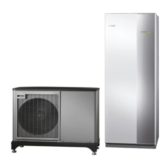
- Page 1 INSTALLATION GUIDE + PRE-COMMISSIONING CHECKLIST F2040 6/8/12KW + VVM320 NB. This reference guide is supplementary to the NIBE installation manual and is not intended to replace it.
- Page 2 Positioning of F2040 (outdoor unit) ➢ Position the F2040 as close as practically possible to the VVM320, a Maximum of ten metres between units is recom- mended to minimize heat loss and reduce running costs. ➢ Install on a solid Base or wall bracket (second story height not recommended).
- Page 3 Positioning of VVM320 (indoor unit) ➢ Leave sufficient space in front of the unit for servicing as per the manual. ➢ Leave minimum 25mm behind unit for pipes/cables. ➢ Use adjustable feet to level the unit. ➢ Leave access to filters/valves for servicing. Page | 3...
- Page 4 Mechanical Connection of F2040 ➢ Connect to the unit using the supplied flexible hoses with minimum use of elbows. ➢ The Flexible hose incorporating a Manual air vent must be on the flow pipe (top connection). ➢ Flexis/pipework must be insulated and weatherproofed with a UV stable product.
- Page 5 Mechanical Connection of VVM320 Pipe connections (22mm) Strainer Valve Tundish at rear of unit Secondary return connection inside unit (15mm) Page | 5...
- Page 6 ➢ The strainer valve supplied should be installed on the return pipe to the F2040 to protect the internal heat exchanger. The direction of flow is indicated on the valve body and must be adhered to. It should be installed to allow easy re- moval of the centre nut for cleaning purposes.
- Page 7 Page | 7...
- Page 8 Electrical Connection of F2040 F2040 Communication board (AA23) ➢ The mains cable is pre-wired in the unit and must be terminated in a local rotary isolator. (not a cooker switch) ➢ The rotary isolator must be supplied by 6 or 10 Square cable back to the Fuse board. (dependent on distance and sized by the electrician) ➢...
- Page 9 Electrical Connection of VVM320 VVM320 Communication board (AA3) Additional relay Page | 9...
- Page 10 Electrical Connection of VVM320 ➢ The mains cable is pre-wired in the unit and must be terminated in a local rotary isolator. ➢ The rotary isolator must be supplied by 6 or 10 Square cable back to the fuse board. (dependant on distance and sized by the electrician) ➢...
- Page 11 Filling and venting the system Buffer vent ➢ Fill the central heating side though the filling loop in the VVM320 ➢ Vent the hot water coil via the coil vent ➢ Vent the buffer via the buffer vent ➢ Vent all high points on pipework ➢...
- Page 12 NIBE uplink ➢ Connect the VVM to the router with Cat5e UTP straight with male to male RJ45 connectors. ➢ A planet earth symbol will appear on the main menu screen if the connection is ok. ➢ Follow the connection instructions on www.nibeuplink.com...