Table of Contents
Advertisement
Quick Links
Advertisement
Table of Contents
Troubleshooting

Related Manuals for Vollrath Stoelting F231-2X


Summary of Contents for Vollrath Stoelting F231-2X
- Page 1 A VOLLRATH® DIVISION Model F231-2X OPERATORS MANUAL Manual No. 513707 Rev.2...
- Page 3 Stoelting White Glove Service. For warranty information, visit stoeltingfoodservice.com Stoelting Foodservice Equipment White Glove Service Network 502 Highway 67 Phone: 888.319.9549 Kiel, WI 53042-1600 A VOLLRATH® DIVISION U.S.A. © 2020 Stoelting stoeltingfoodservice.com...
- Page 4 A Few Words About Safety Safety Information Safety Alert Symbol: Read and understand the entire manual before This symbol Indicates danger, warning or caution. operating or maintaining Stoelting equipment. Attention is required in order to avoid serious personal injury. The message that follows the symbol contains This manual provides the operator with information important information about safety.
-
Page 5: Table Of Contents
TABLE OF CONTENTS Section Description Page Description and Specifi cations Description ....................1 Specifi cations ..................... 1 Installation Instructions Safety Precautions ..................3 Shipment and Transit .................. 3 Machine Installation ..................3 IntelliTec2™ Setup ..................4 Initial Set-Up and Operation Operator’s Safety Precautions .............. -
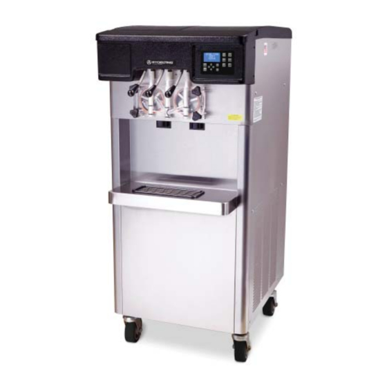
Page 7: Description
This manual is designed to assist qualifi ed service per- sonnel and operators in the installation, operation and maintenance of the Stoelting F231-2X gravity machine. Figure 1-1 Model F231-2X 1.2 SPECIFICATIONS Figure 1-2 Specifi cation Owner’s Manual #513707... - Page 8 SPECIFICATIONS Model F231-2X Dimensions Machine as shipped width 25-5/8’’ (65,1 cm) 40-1/4’’ (102,2 cm) height 57-3/4’’ (146,7 cm) 64-1/2’’ (163,8 cm) depth 33-3/4’’ (85,7 cm) 33-1/4’’ (84,5 cm) Weight 640 lbs (290,2 kg) 730 lbs (331,1 kg) Electrical 1 Phase, 208-240 VAC, 60Hz 3 Phase, 208-240 VAC, 60Hz running amps 13.5 A...
-
Page 9: Installation Instructions
SECTION 2 INSTALLATION INSTRUCTIONS 2.1 SAFETY PRECAUTIONS PRIOR TO INSTALLATION Locate a copy of the service contact fi le (info.txt). Do not attempt to operate the machine until the safety precautions and operating instructions in this manual are Modify the info.txt fi le with information from the read completely and are thoroughly understood. -
Page 10: Intellitec2™ Setup
2.4 INTELLITEC2™ SETUP After the password is accepted, use the arrows to move the cursor to the Modify Settings option and Disassemble, clean, lubricate and assemble the press the SEL button. Then move the cursor to machine following the steps in Section 3. the User Preferences and press the SEL button. - Page 11 SETTING TIME AND DATE SETTING SERVE TIME AND OVERRUN DETAILS Press the right arrow button. Go to the Advanced Settings (2 of 3) screen and scroll down to the Time to Dispense 16 oz option. Move the cursor to the Modify Settings option and press the SEL button.
- Page 12 Owner’s Manual #513707 F231-2X Model Machines...
-
Page 13: Initial Set-Up And Operation
SECTION 3 INITIAL SET-UP AND OPERATION 3.1 OPERATOR’S SAFETY PRECAUTIONS 3.2 OPERATING CONTROLS AND INDICATORS SAFE OPERATION IS NO ACCIDENT; observe these Before operating the machine, it is required that the op- rules: erator know the function of each operating control. Refer to Figure 3-1 for the location of the operating controls on Know the machine. -
Page 14: Emptying The Freezing Cylinder
Remove the hopper covers and remove the mix inlet regulators from the hoppers. Press the Clean button. After about 5 minutes open the spigot to drain the mix. Press the Clean buttons to stop the augers. Fill each hopper with 1 gallon of cool tap water. Optional: Use detergent solution instead of tap water to make cleaning the parts easier after Figure 3-2 IntelliTec2 Control... -
Page 15: Cleaning Disassembled Parts
A. DISASSEMBLY OF FRONT DOOR Press and hold the Main Freezer Power button for three seconds to turn the power off. Remove the rosette caps or spigot extensions if installed. Remove the knobs on the front door. Remove the front door by pulling it off the studs. Remove the spigot through the bottom of the front door. -
Page 16: Assembling Machine
ASSEMBLING MACHINE Install the remaining plastic fl ights, push the auger into the freezing cylinder and rotate slowly until To assemble the machine parts, refer to the following steps: the auger engages the drive shaft. NOTICE Apply a thin layer of sanitary lubricant to the inside Total Blend sanitary lubricant, Petrol-Gel sanitary and outside of the auger support bushing. -
Page 17: Freeze Down And Operation
FREEZE DOWN AND OPERATION Sanitize immediately before use. Fill the hopper with at least 2.5 gallons of mix. Position Air Place a container under the spigot and open the Tube Towards spigot to allow the mix to fl ush out about 8 ounces Front of Machine (0.23 liters) of sanitizing solution and liquid mix. -
Page 18: Mix Information
3.10 MIX INFORMATION Mix can vary considerably from one manufacturer to another. Differences in the amount of butterfat content and quantity and quality of other ingredients have a direct bearing on the fi nished frozen product. A change in machine performance that cannot be explained by a technical problem may be related to the mix. -
Page 19: Maintenance And Adjustments
SECTION 4 MAINTENANCE AND ADJUSTMENTS This section is intended to provide maintenance personnel Use a Burroughs Belt Tension Gauge to set the with a general understanding of the machine adjustments. tension for the drive belt. Set the belt tension to It is recommended that any adjustments be made by a 50-55 lbs. -
Page 20: Preventative Maintenance
EXTENDED STORAGE To remove a condenser fi lter, grasp the top and pull off. Visually inspect the fi lter for dirt. If it is Refer to the following steps for storage of the machine dirty, shake or brush excess dirt off of it and wash over any long period of shutdown time: it in warm, soapy water. -
Page 21: Troubleshooting
SECTION 5 TROUBLESHOOTING 5.1 ERROR CODES Error Code 3 - Run Time The Run Time Error (E3) occurs when the When the machine experiences a problem, one of the compressor runs continuously for an extended following error codes will be displayed on the control period. - Page 22 Error Code 5 - Freezing Cylinder Sensor Error Code 11 - Prime Error The Freezing Cylinder Sensor Error (E5) indicates The Prime Error (E11) will not occur on the a failure of the barrel sensor or if the sensor is machine.
-
Page 23: Troubleshooting - Machine
5.3 TROUBLESHOOTING - MACHINE PROBLEM POSSIBLE CAUSE REMEDY 1 Power to machine is off. 1 Supply power to machine. Machine does not 2 Freeze-up (auger will not turn). 2 Turn machine off for 15 minutes, then restart. run. 3 Front door not in place. 3 Assemble front door in place. - Page 24 Owner’s Manual #513707 F231-2X Model Machines...
-
Page 25: Replacement Parts
SECTION 6 REPLACEMENT PARTS DECALS AND LUBRICATION Part Description Quantity 208135 Brush - 4” X 8” X 16” (Barrel) 208380 Brush - 1/4” X 3” X 14” 208401 Brush - 1” X 3” X 10” 208467 Brush - 3/8” X 1” X 5” 236059 Card - Cleaning Instruction C-1000-26C... -
Page 26: Auger Shaft And Faceplate Parts
AUGER SHAFT AND FACEPLATE PARTS 624678 624678 381804 381804 694255 694255 2177428 2177428 625133 625133 2205440 2205440 666786 666786 4157986-SV 4157986-SV 149003 149003 482019 482019 2187811 2187811 2187812 2187812 624614 624614 624598 624598 624664 624664 Part Description Quantity 149003 Bushing - Front Auger Support 381804 Auger Flight 482019... -
Page 27: Hopper Parts And Trays
HOPPER PARTS AND TRAYS 624677 624677 2177072 2177072 2206567 2206567 2206566 2206566 2206992 2206992 2077074 2077074 2077073 2077073 2206991 2206991 232741 232741 2204806 2204806 2149243-01 2149243-01 744607 744607 417006 417006 2206858 2206858 744273 744273 624677 624677 Part Description Quantity 232741 Cap - Rosette (6-Point Teardrop) (Translucent) 417006 Grid - Drip Tray (Vinyl Coated Metal) - Page 28 Owner’s Manual #513707 F231-2X Model Machines...
Need help?
Do you have a question about the Stoelting F231-2X and is the answer not in the manual?
Questions and answers