
Related Manuals for Vollrath FlexVent


Summary of Contents for Vollrath FlexVent
- Page 1 INSTALLATION MANUAL FlexVent™ Versatile Slide-In with Downdraft Vent System and Fire Suppression ©2022 The Vollrath Company L.L.C. 7/15/2022...
-
Page 2: Safety Information
SAFETY INFORMATION This manual provides information for safely configuring, installing, operating, and maintaining FlexVent™. Always follow guid- ance from the Authority Having Jurisdiction (AHJ) for regulation and code compliance. DO NOT install or operate the unit until all safety information and instructions are thoroughly read and understood. Installation and startup must be performed by a qualified technician. - Page 3 Using other areas to lift will cause damage to the unit. DAMAGE RESULTING FROM IMPROPER HANDLING WILL VOID THE WARRANTY. • Remove and retain the envelope that contains included hardware, labels, and documentation. Model FC-6DV | Installation Guide © 2022 The Vollrath Company L.L.C. | Part No. 354139 | 7/12/2022...
-
Page 4: Table Of Contents
Wok ..............................20 Panini/Sandwich Press ........................20 Appliance Nozzle Locations and Setup ....................21 Fire Suppression System ........................22 Filters ..............................23 Maintenance & Service Log .........................23 Wiring Diagram & Schematic ......................24-26 Troubleshooting ...........................28 Service, Repair & Warranty ........................29 BACK TO TOC Flexvent™ installation manual... - Page 5 BACK TO TOC Flexvent™ installation manual...
-
Page 6: Introduction
Carefully review and understand this manual thoroughly before proceeding with installation, commissioning, and operation of FlexVent™. This unit has been designed for customized over, under, or flush counter instal- lation in the front or back of the house as determined by the Authority Having Jurisdiction (AHJ). The unit is UL Recognized and as such, must be completed by a fabricator in compliance with the applicable UL Certifi- cation, the UL Conditions of Acceptability, and requirements of the AHJ. -
Page 7: Location & Clearance
LOCATION The space in which FlexVent™ is located is considered to be part of the kitchen. Therefore, regulations pertaining to a commercial kitchen may apply. These include but are not limited to: fresh air, airflow, air exchanges, floor area, and proximity to customer seating area. Location of the unit must comply with AHJ requirements and jurisdiction codes. -
Page 8: Functional Description/Systems Overview
FUNCTIONAL DESCRIPTION/SYSTEMS OVERVIEW FlexVent™ has three 165 °F fusible links arranged in a series under the Vent Hood and behind the Particulate Filters. If any link is actuated, the Fire Suppression System is activated. In the event the Fire Suppression System is activated (automatically or manually), power to the cooking appliance(s) and fan motor is terminated. -
Page 9: Required Parts Supplied By Installer
• Appliance conduit and wiring, etc. for customized configuration Mechanical • Cabinet surround & countertop • Ventilation cover — Separate Vollrath® purchase or fabricator provided. Must be removable and en- able complete access for service. The cover must provide a minimum of 80 square inches of open area for proper ventilation and exhaust. -
Page 10: Ul Conditions Of Acceptability
10. The covered Downdraft table assembly component is intended to be factory installed only. 11. If legs/feet or casters are not provided as part of the Recognized Component table, the supporting means should be evaluated in the end use and Stability Test should be considered. BACK TO TOC Flexvent™ installation manual... -
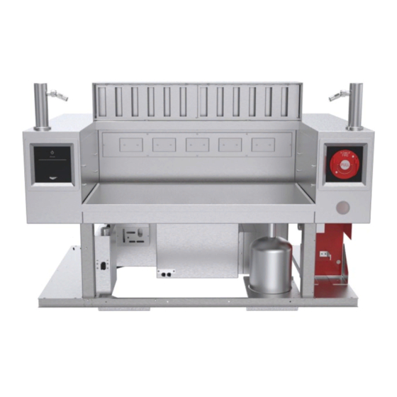
Page 11: System Overview
R. Discharge Nozzles (Duct) (2) S. ANSUL Detector Brackets w/ Fusible Links (3) T. Lift and Mounting Pads *Supplied and installed separately. **For service technician use. BACK TO TOC Flexvent™ installation manual FlexVent™ Versatile Slide-In with Downdraft Vent System and Fire Suppression Operator’s Manual... -
Page 12: Cabinet Constraints & Installation
COUNTERTOP 86.4 BASE 29 7/8 75.9 BOTTOM OF 53 5/8 COUNTERTOP 136.2 DIMENSIONS RESULT IN APPLIANCE UNDER COUNTERTOP. COUNTERTOP OVERLAPS APPLIANCE APPROXIMATELY 1/2" [1.3 CM] ON SIDES. COUNTERTOP WILL NOT OVERLAP APPLIANCE IN BACK. BACK TO TOC Flexvent™ installation manual... -
Page 13: Led Lighting (Optional)
LED LIGHTING (OPTIONAL) By default, the LED switch is disabled and the switch and indicator will not be visible. main power To enable the LED function: 1. With power to touch panel (Vollrath logo lit) and Press high pressure low pressure &... -
Page 14: Cooking Appliance Constraints - Electric Only
• Usable appliance space 18 1/4” D X 35 3/4” W • Allowable grease discharge per UL 710B and NFPA 96 is 5 mg/m (0.00018 oz/ft ). No configuration shall exceed the total allowable discharge. EFFLUENT CAPTURE AND FIRE SUPPRESSION BOUNDARIES (SHELF NOT SHOWN) BACK TO TOC Flexvent™ installation manual... - Page 15 BACK TO TOC Flexvent™ installation manual...
-
Page 16: Induction
Dia. Max. Any* 550 °F 3600/hob — 7200 total 14” COOKING SURFACE HEIGHT LIMIT COOKING SURFACE HEIGHT LIMIT COOKING SURFACE HEIGHT LIMIT *Shelf positions are top, middle, and bottom. BACK TO TOC Flexvent™ installation manual... - Page 17 Shelf Position Max Watts Pot/Pan Temp Dia. Max Any* 550 °F 3600/hob — 7200 total 14” COOKING SURFACE HEIGHT LIMIT COOKING SURFACE HEIGHT LIMIT *Shelf positions are top, middle, and bottom. BACK TO TOC Flexvent™ installation manual...
-
Page 18: Fryer
Max Surface Oil Temp 15 lbs oil/vat Bottom 375 °F 3600/vat —7200 total 132 sq in/vat COOKING SURFACE HEIGHT LIMIT COOKING SURFACE HEIGHT LIMIT COOKING SURFACE HEIGHT LIMIT BACK TO TOC Flexvent™ installation manual... -
Page 19: Griddle
Shelf Position Max Temp Max Watts Max Surface Area Bottom 550 °F 3600 total 396 sq in COOKING SURFACE HEIGHT LIMIT COOKING SURFACE HEIGHT LIMIT COOKING SURFACE HEIGHT LIMIT BACK TO TOC Flexvent™ installation manual... -
Page 20: Wok
SANDWICH/PANINI GRILL CONSTRAINTS — ELECTRIC ONLY Sandwich/Panini Shelf Position Max Temp Max Watts Press(es) Any* 550 °F 3600/press — 7200 total COOKING SURFACE HEIGHT LIMIT COOKING SURFACE HEIGHT LIMIT *Shelf positions are top, middle, and bottom. BACK TO TOC Flexvent™ installation manual... -
Page 21: Appliance Nozzle Locations And Setup
APPLIANCE NOZZLE LOCATIONS AND SETUP 9 1/8 23.2 30.3 30.3 SHELF TO BE IN LOWEST POSITION BACK TO TOC Flexvent™ installation manual... -
Page 22: Fire Suppression System
ANSUL R-102 1W Nozzle (Duct) ANSUL R-102 1.5 Gallon Tank Fill the agent tank with ANSULEX low pH Liquid Fire Suppressant. NOTE: Final product may not appear as depicted. BACK TO TOC Flexvent™ installation manual ™ V ’ ERSATILE LIDE N WITH... -
Page 23: Filters
Monthly Interlock System Test Quarterly Plenum Cleaning Fire Suppression System Maintenance Semi-Annual Fire Suppression Inspection & Maintenance Annual Fire Suppression System Inspection & Maintenance 12-Year Fire Suppression System Inspection & Maintenance Maintenance & Service Log BACK TO TOC Flexvent™ installation manual... -
Page 24: Wiring Diagram & Schematic
WIRING DIAGRAM & SCHEMATIC +10VDC (RED) SPEED (YELLOW) GROUND (BLUE) WHITE GREEN BLUE BROWN CUSTOMER SUPPLIED LED POWER SUPPLY 120 VAC BACK TO TOC Flexvent™ installation manual... - Page 25 WIRING DIAGRAM & SCHEMATIC CUSTOMER SUPPLIED LED POWER SUPPLY BACK TO TOC Flexvent™ installation manual...
- Page 26 (R1) FOR PRESET TIME (60 SECONDS). THIS ALLOWS THE SYSTEM TIME TO STABILIZE AT OPERATING PRESSURE. M1 = FAN MOTOR RUNS WHEN CONTROL RELAY (R1) IS CLOSED. CB1 = MAIN OUTPUT BREAKER FEEDS MAIN POWER TO CUSTOMER SUPPLIED DISTRIBUTION BREAKER BOX AND OUTLETS. BACK TO TOC Flexvent™ installation manual...
- Page 27 BACK TO TOC Flexvent™ installation manual...
-
Page 28: Troubleshooting
Unit will not operate There is no power. •Reconnect to electrical power. — logo is not •Reset circuit breaker for unit. illuminated. •Contact Vollrath Technical Services. The ANSUL Fire Suppression ® Contact an authorized ANSUL ® System was not properly representative for repair. -
Page 29: Service, Repair & Warranty
WARRANTY STATEMENT FOR THE VOLLRATH CO. This warranty does not apply to products purchased for personal, family, or household use, and The Vollrath Company LLC does not offer a written warranty to purchasers for such uses.
Need help?
Do you have a question about the FlexVent and is the answer not in the manual?
Questions and answers