
Related Manuals for SCHUNK EOA-UR3510-EGL90


Summary of Contents for SCHUNK EOA-UR3510-EGL90
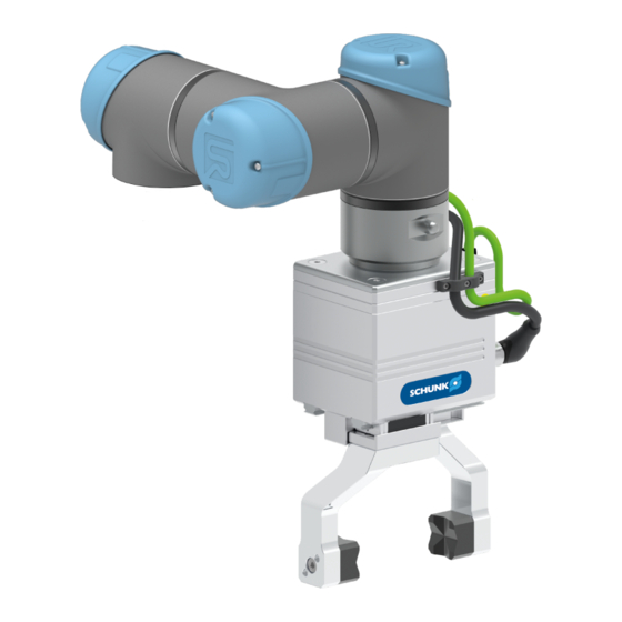
- Page 1 Translation of Original Operating Manual Assembly and Operating Manual ID 1392477 or 1403607 Gripping Unit - EOA-UR3510-EGL90 or EOA-UR3510-EGL90-AUB...
- Page 2 Imprint Copyright: This manual is protected by copyright. The author is SCHUNK GmbH & Co. KG. All rights reserved. Any reproduction, processing, distribution (making available to third parties), translation or other usage - even excerpts - of the manual is especially prohibited and requires our written approval.
-
Page 3: Table Of Contents
Table of Contents Table of Contents General........................ 5 About this manual .................... 5 1.1.1 Presentation of Warning Labels ............... 5 1.1.2 Applicable documents ................ 6 Warranty ...................... 7 Scope of delivery .................... 8 Basic safety notes .................... 9 Intended use...................... 9 Not intended use .................... 9 Spare parts ...................... - Page 4 Table of Contents Start-up ........................ 36 "URCap" software.................... 36 6.1.1 Functional description ................ 36 6.1.2 Compatibility with UR robots .............. 36 Installing the software component .............. 37 Connecting the robot with a network .............. 40 Establishing a connection to the gripper............ 41 Configuring the gripper .................. 42 Creating the robot program ................
-
Page 5: General
General 1 General 1.1 About this manual This manual contains important information for a safe and appropriate use of the product. This manual is an integral part of the product and must be kept accessible for the personnel at all times. Before starting work, the personnel must have read and understood this operating manual. -
Page 6: Applicable Documents
The applicable documents can be found on the enclosed CD. Content of the CD Documentation Parallel Gripper EGL * Annex 1 Software manual "Motion Control SCHUNK" * Annex 2 "SCHUNK Drive Protocol (SDP)" software manual * Annex 3 Connection diagram Annex 4 Drawing Annex 5... -
Page 7: Warranty
General 1.2 Warranty If the product is used as intended, the warranty is valid for 24 months from the ex-works delivery date under the following conditions: • Observe the specified maintenance and lubrication intervals • Observe the ambient conditions and operating conditions Parts touching the workpiece and wear parts are not included in the warranty. -
Page 8: Scope Of Delivery
General 1.3 Scope of delivery The scope of delivery includes • Gripping Unit - EOA-UR3510-EGL90 or EOA-UR3510-EGL90-AUB ID 1392477 or 1403607 in the version ordered • Top jaw set (only for EOA-UR3510-EGL90-AUB) • USB stick with URCap and Assembly and Operating Manual •... -
Page 9: Basic Safety Notes
Basic safety notes 2 Basic safety notes 2.1 Intended use The gripper unit was designed as a version of the UR kit for attachment to a robot with ISO-50 interface. The gripper unit with integrated valves and sensor interface is used in the robot application. -
Page 10: Spare Parts
Use of unauthorized spare parts Using unauthorized spare parts can endanger personnel and damage the product or cause it to malfunction. • Use only original spare parts or spares authorized by SCHUNK. 2.4 Gripper fingers Requirements for the gripper fingers Stored energy within the product creates the risk of serious injuries and significant property damage. -
Page 11: Personnel Qualification
Basic safety notes 2.6 Personnel qualification Inadequate qualifications of the personnel If the personnel working with the product is not sufficiently qualified, the result may be serious injuries and significant property damage. • All work may only be performed by qualified personnel. •... -
Page 12: Personal Protective Equipment
Basic safety notes 2.7 Personal protective equipment Use of personal protective equipment Personal protective equipment serves to protect staff against danger which may interfere with their health or safety at work. • When working on and with the product, observe the occupational health and safety regulations and wear the required personal protective equipment. -
Page 13: Transport
Basic safety notes 2.9 Transport Handling during transport Incorrect handling during transport may impair the product's safety and cause serious injuries and considerable material damage. • When handling heavy weights, use lifting equipment to lift the product and transport it by appropriate means. •... -
Page 14: Fundamental Dangers
Basic safety notes 2.12 Fundamental dangers General • Observe safety distances. • Never deactivate safety devices. • Before commissioning the product, take appropriate protective measures to secure the danger zone. • Disconnect power sources before installation, modification, maintenance, or calibration. Ensure that no residual energy remains in the system. -
Page 15: Protection During Commissioning And Operation
Basic safety notes 2.12.2 Protection during commissioning and operation Falling or violently ejected components Falling and violently ejected components can cause serious injuries and even death. • Take appropriate protective measures to secure the danger zone. • Never step into the danger zone during operation. 2.12.3 Protection against dangerous movements Unexpected movements Residual energy in the system may cause serious injuries while... -
Page 16: Protection Against Electric Shock
Basic safety notes 2.12.4 Protection against electric shock Possible electrostatic energy Components or assembly groups may become electrostatically charged. When the electrostatic charge is touched, the discharge may trigger a shock reaction leading to injuries. • The operator must ensure that all components and assembly groups are included in the local potential equalisation in accordance with the applicable regulations. -
Page 17: Notes On Particular Risks
Basic safety notes 2.13 Notes on particular risks WARNING Risk of injury due to unexpected movements! If the power supply is switched on or residual energy remains in the system, components can move unexpectedly and cause serious injuries. Before starting any work on the product: Switch off the power •... - Page 18 Basic safety notes WARNING Danger of injury due to uncontrolled movements! Due to incorrect control and incorrect operation, loss of workpieces and uncontrolled movement of the product may occur and can cause serious injuries. Take checks in the user's program. •...
-
Page 19: Technical Data
[A] Interface PROFINET [100 MBit/s] USB Mini AB, device, parameterization interface USB Micro AB, host * SCHUNK recommends: Littelfuse 1A time delay (0154001 .DRTL) 01.00 | ID 1392477 or 1403607 | Assembly and Operating Manual | en | 1405195... - Page 20 Technical data Illustration of coordinate system for TCP and center of gravity Dimensions and maximum loads (max.) 20 Nm (max.) 20 Nm (max.) 20 Nm (max.) 400 N The indicated moments and forces are static values, apply for each base jaw, and may occur simultaneously. M may arise in addition to the moment generated by the gripping force itself.
-
Page 21: Ambient Conditions And Operating Conditions
* For use in dirty ambient conditions (e.g. sprayed water, vapors, abrasion or processing dust) SCHUNK offers corresponding product options as standard. SCHUNK also offers customized solutions for special applications in dirty ambient conditions. 01.00 | ID 1392477 or 1403607 | Assembly and Operating Manual | en | 1405195... -
Page 22: Design
Design 4 Design 4.1 Complete unit Structure of the complete unit Item Designation Communication cable PROFINET with angled M12 plug Electrical connector as well as robot-side RJ45 plug connector connection 28] Voltage supply connection cable with angled M12 plug Electrical connector as well as robot-side open wire ends connection 28]... -
Page 23: Gripping Unit Egl
Design 4.2 Gripping unit EGL 2-finger parallel gripper EGL, using PROFINET variant as an example Finger interface Housing PROFINET socket PROFINET socket Voltage supply connector Service window Finger centering sleeves 01.00 | ID 1392477 or 1403607 | Assembly and Operating Manual | en | 1405195... -
Page 24: Assembly
Assembly 5 Assembly 5.1 Installing and connecting DANGER Danger from electric voltage! Touching live parts may result in death. Switch off the power supply before any assembly, adjustment or • maintenance work and secure against being switched on again. Only qualified electricians may perform electrical installations. •... -
Page 25: Connections
Assembly 5.2 Connections 5.2.1 Mechanical connection WARNING Risk of injury from falling of the product! During transport and assembly/disassembly the product may fall down and cause serious injuries. Secure the product with adequately sized aids. • Wear suitable protective clothing. •... - Page 26 Assembly Take cylinder pin (2) from the accessory kit. Ø Insert cylinder pin (2) into the ISO A50 flange (1). Ø Place the upper adapter plate (3) on the ISO flange. Ø Take the hexagon socket wrench A/F 5 from the accessory kit. Ø...
- Page 27 Assembly Take cylinder pins (3) from the accessory kit. Ø Insert cylinder pins (3) into the gripping unit. Ø Fasten the gripping unit (4) to the adapter plate (1) using screws Ø (1) and the hexagon socket wrench A/F 4. Further information contains the assembly drawing on the CD.
-
Page 28: Electrical Connection
Assembly 5.2.2 Electrical connection CAUTION Risk of damage to the electronics! A faulty connection can cause damage to the internal electronics. The supply network must be a network of type "PELV" for • power and logic. Observe the PIN assignment of the connecting terminals. •... - Page 29 Assembly 5.2.2.2 PIN allocation for voltage supply PIN allocation for voltage supply Logic voltage +24V Logic voltage GND Motor voltage GND Motor voltage +24V 5.2.2.3 PIN allocation for PROFINET PROFINET PROFINET is achieved via two M12 sockets. The sockets of the PROFINET are D-coded.
- Page 30 Assembly 5.2.2.4 Wiring diagram Motor voltage +24V Motor voltage GND Logic voltage GND Logic voltage +24V Wiring diagram 01.00 | ID 1392477 or 1403607 | Assembly and Operating Manual | en | 1405195...
- Page 31 Assembly Under 70% gripping force At a gripping force up to 70%, the gripper can be connected to the voltage supply of the robot. Connection of an external power supply unit via bypass (optional); for details, see the operating manual of the robot Connections for EGL voltage supply (suggestion) Connections on the robot control system 01.00 | ID 1392477 or 1403607 | Assembly and Operating Manual | en | 1405195...
- Page 32 EGL can be connected directly to an external power supply unit with 24V DC/3A (stabilized and smoothed). The SCHUNK range includes an appropriate power supply unit (order number: 31001408). • Connection of an external power supply unit to the voltage...
-
Page 33: Installing Gripper Fingers
5.3 Installing gripper fingers NOTE For the gripping unit with ID 1392477, the gripper fingers are available as accessories from SCHUNK; see the catalog data sheet for further information. The finger set consists of the top jaws and two clamping inserts. - Page 34 Assembly At the factory, the top jaws are installed on the base jaws of the Clamping insert with gripper as illustrated in the following graphic. The gripper pads are gripper pads – used to increase the coefficient of friction. outside gripping 85 Gripper open 32 Gripper closed 85 Gripper open...
- Page 35 Assembly For inside gripping of a workpiece, the clamping range is 102 mm Clamping insert with to 187 mm. gripper pads – inside gripping 102 Gripper closed 187 Gripper open Clamping insert with gripper pads with a clamping range of 102 mm to 187 mm Clamping inserts with With the prismatic clamping inserts (included in the accessory kit), cylindrical workpieces with a diameter of 7 mm to 40 mm can be...
-
Page 36: Start-Up
6.1 "URCap" software 6.1.1 Functional description The "URCap" software is used for simple commissioning and programming of the SCHUNK gripper EGL 90 in combination with robots from Universal Robots. The "URCap" software is integrated seamlessly into the programming environment of Universal Robots. -
Page 37: Installing The Software Component
Start-up 6.2 Installing the software component NOTE To install the software, use the enclosed USB stick. Connect the USB stick to the control panel of the robot. The Ø USB interface is located at the back. Switch on the control panel and select the "Configure Robot Ø... - Page 38 Start-up Select the "System" button in the left menu. Ø A submenu opens. ✓ Select the "URCaps" button. Ø The already active URCaps are displayed in the left Explorer ✓ window. Inactive URCaps are displayed in the window on the right.
- Page 39 Start-up Select the "+" button to install a new URCap. Ø Select "USB Disk". Ø Select the "SCHUNK_Gripper_EGL-1.0.0.urcap" software Ø component. Select the "+" button to install a software component on the Ø control panel. Select the "Restart" button to complete the installation. Ø...
-
Page 40: Connecting The Robot With A Network
Start-up 6.3 Connecting the robot with a network Select the "System" button in the left menu. Ø A submenu opens. ✓ Select the "Network" button. Ø The network settings are displayed in the Explorer window. ✓ Configure the connection via "Static IP Address". Ø... -
Page 41: Establishing A Connection To The Gripper
Select the "Installation" button in the header line. Ø Select the "URCaps" button in the left menu. Ø A submenu opens. ✓ Select the "SCHUNK EGL Gripper" button. Ø The Explorer window displays the configuration data and an ✓ image of the product. NOTE If no MAC address is displayed, select the "Update"... -
Page 42: Configuring The Gripper
Select the "Installation" button in the header line. Ø Select the "URCaps" button in the left menu. Ø A submenu opens. ✓ Select the "SCHUNK EGL Gripper" button. Ø The Explorer window displays the configuration data and an ✓ image of the product. Configure the gripper. - Page 43 Start-up Configuration options on the product Specification Basic setting Note Reference type SpeedLeft Various referencing options are available to optimize the accuracy of different gripping tasks. Reference offs. 0.0 mm To move the origin of the coordinate system, e.g. if the finger geometry results in a minimum opening > 0.0 mm.
-
Page 44: Creating The Robot Program
Start-up 6.6 Creating the robot program Select the "Program" button in the header line. Ø The robot program and a short description for creating the ✓ program are displayed in the Explorer window. The following commands can be selected and configured for a robot program: Command Function... -
Page 45: Selecting And Configuring Commands
Start-up 6.6.1 Selecting and configuring commands Select the desired command from the URCap commands in the Ø left menu. The selected command appears under "Robot Program". ✓ The input fields for configuring the command are displayed in ✓ the Explorer window. The current position of the gripper fingers is displayed in the ✓... - Page 46 Start-up WARNING Risk of injury from crushing and impacts! A command is performed immediately by selecting the "Test" button. The gripper can apply a force of up to 600 N. Only operate the gripper behind closed safety devices, e.g. a • protective fence.
- Page 47 Start-up 6.6.1.1 EGL Commands The following basic functions are combined in this command: Function Description Stop The gripper performs a controlled stop. The gripper remains operational for further commands. Fast stop The gripper immediately short-circuits the motor phases; the position brake is applied with a delay. Reference Redetermine the zero point of the gripper coordinate system.
- Page 48 Start-up 6.6.1.2 EGL Position In the input field, enter the desired position for the gripper. Ø Select the "Test" button. Ø The gripper moves to the desired position. ✓ NOTE This command is not intended for gripping components. 01.00 | ID 1392477 or 1403607 | Assembly and Operating Manual | en | 1405195...
- Page 49 Start-up 6.6.1.3 EGL Grip WARNING Risk of injury and property damage from ejected and falling parts! When moving and accelerating the robot arm, the gripped workpiece may come loose and injure persons or damage objects in its vicinity. Use an external power supply unit for a gripping force > 70%. •...
- Page 50 Start-up Description Message Outside gripping Outside gripping of a workpiece with The grip is reported as unknown dimensions. The gripper successful moves from the current position in ("eglGraspOK()"=1) if the the direction of the minimum end stop is not reached. position.
- Page 51 This command is not intended for gripping components. NOTE For further information, see the documentation of the EGL and the software manual "SDP SCHUNK Drive Protocol", Applicable documents. The following settings can be configured: 01.00 | ID 1392477 or 1403607 | Assembly and Operating Manual | en | 1405195...
- Page 52 Start-up Setting Description Parameter Relative position To perform a relative movement. "Position", "Speed", The transferred position value is "Acceleration", "Jerk" and used as the traverse path. For a "Force" are used for positive value, the gripper fingers detailed fine adjustment are opened along the specified path;...
-
Page 53: Monitoring The Gripper Status
Start-up 6.7 Monitoring the gripper status The status of the gripper is monitored via standard functions of the UR robot, e.g. to declare a gripper feedback signal as a variable. Select the "Advanced" button in the left menu. Ø A submenu opens. ✓... - Page 54 Start-up Expand the "Function" drop-down menu at the bottom left. Ø Scroll to the heading "SCHUNK Gripper EGL for UR - SCHUNK Ø GmbH & Co.". Different functions are displayed under the heading. ✓ Function Description eglIsInPos() The system returns the value "1" if a position movement was triggered and the target position was reached.
- Page 55 The system returns the value "0" if the gripper is operational. An error ID is returned if there is an error message. For more detailed information on the error IDs, see the software manual "SDP SCHUNK Drive Protocol", Applicable documents 6].
-
Page 56: Trouble Shooting
7 Trouble shooting Once an error with an error message is eliminated, this error message must be acknowledged, see the "SCHUNK Motion Protocol (SMP)" and "SCHUNK Drive Protocol (SDP)" software manuals. The error is indicated in the service window via LED 4. -
Page 57: Product Does Not Open
Check power supply fuse and replace if necessary. Error message pending Eliminate errors and acknowledge error message, see the "SCHUNK Motion Protocol (SMP)" and "SCHUNK Drive Protocol (SDP)" software manuals. Setpoint settings for current, speed, jerk and Check setpoint settings and enter suitable acceleration are not suitable or too low values, see the "SCHUNK Motion Protocol... -
Page 58: Maintenance
Incorrect works can cause damage to the mechanics and internal electronics. Disassembly or opening of the product is not permitted. • Only allow SCHUNK to repair the product. • 01.00 | ID 1392477 or 1403607 | Assembly and Operating Manual | en | 1405195... -
Page 59: Spare Parts And Wearing Parts
Spare parts and wearing parts 9 Spare parts and wearing parts Item ID number Designation Quant- Spare spart [s.p.] / wear part [w.p.] 1325750 PROFINET communication cable torsion compatible 1405098 EGL90 power cable torsion compatible 1405800 Top jaws (set incl. clamping inserts with gripper pads HKI or double prism) 1405803 Clamping insert with gripper pads *... -
Page 60: Eu-Declaration Of Conformity
- Interference emissions in residential, commercial, industrial and light industrial environments IEC 61000-6-3: 2006 + A1:2010 Signed for and on behalf of: SCHUNK GmbH & Co. KG Jochen Ehmer, Global Head of Business Unit, Gripping Systems Lauffen/Neckar, August 2019... -
Page 61: Translation Of Original Declaration Of Incorporation
11 Translation of original declaration of incorporation in terms of the Directive 2006/42/EG, Annex II, Part 1.B of the European Parliament and of the Council on machinery. Manufacturer/ SCHUNK GmbH & Co. KG Spann- und Greiftechnik Distributor Bahnhofstr. 106 – 134 D-74348 Lauffen/Neckar... -
Page 62: Annex To Declaration Of Incorporation
1.Description of the essential health and safety requirements pursuant to 2006/42/EC, Annex I that are applicable and that have been fulfilled with: Product designation Gripping Unit - EOA-UR3510-EGL90 or EOA-UR3510-EGL90-AUB, ID 1392477 or 1403607 To be provided by the System Integrator for the overall machine ⇓... - Page 63 Annex to Declaration of Incorporation Protection against mechanical hazards 1.3.7 Risks related to moving parts 1.3.8 Choice of protection against risks arising from moving parts 1.3.8.1 Moving transmission parts 1.3.8.2 Moving parts involved in the process 1.3.9 Risks of uncontrolled movements Required characteristics of guards and protective devices 1.4.1 General requirements...
- Page 64 Annex to Declaration of Incorporation Information 1.7.1 Information and warnings on the machinery 1.7.1.1 Information and information devices 1.7.1.2 Warning devices 1.7.2 Warning of residual risks 1.7.3 Marking of machinery 1.7.4 Instructions 1.7.4.1 General principles for the drafting of instructions 1.7.4.2 Contents of the instructions 1.7.4.3...
Need help?
Do you have a question about the EOA-UR3510-EGL90 and is the answer not in the manual?
Questions and answers