
Subscribe to Our Youtube Channel
Related Manuals for SCHUNK EGN 80


Summary of Contents for SCHUNK EGN 80
- Page 1 Assembly and Operating Manual EGN 2-finger parallel gripper Translation of Original Operating Manual...
- Page 2 Imprint Imprint Copyright: This manual is protected by copyright. The author is SCHUNK SE & Co. KG. All rights reserved. Technical changes: We reserve the right to make alterations for the purpose of technical improvement. Document number: 389056 Version: 13.00 | 24/05/2023 | en...
-
Page 3: Table Of Contents
3.1 Basic data ..................18 3.2 Technical data for the integrated resolver..........20 3.3 Technical data for the integrated motor ........... 21 3.4 SCHUNK power and sensor cable ............. 22 4 Design and description ................23 4.1 Design ....................23 4.2 Description .................. - Page 4 Table of contents 5 Assembly.................... 25 5.1 Assembling and connecting ..............25 5.2 Connections ..................27 5.2.1 Mechanical connection..............27 5.2.2 Electrical connection to the ECM controller ........29 5.3 Connecting the ground cable (functional ground)........35 5.4 Air purge connection for dust-tight (SD) variant......... 36 6 Start-up and system integration via ECM controller ........
-
Page 5: General
General 1 General 1.1 About this manual This manual contains important information for a safe and appropriate use of the product. This manual is an integral part of the product and must be kept accessible for the personnel at all times. Before starting work, the personnel must have read and understood this operating manual. -
Page 6: Applicable Documents
General terms of business * Catalog data sheet of the purchased product * Assembly and operating manuals of the accessories * "SCHUNK Drive Protocol (SDP)" software manual * "SCHUNK Motion Protocol (SMP)" software manual * Wiring diagram * The documents labeled with an asterisk (*) can be downloaded from schunk.com. -
Page 7: Accessories
Controller ECM Power and sensor cables for variant EZN-S Contents of the DVD enclosed with the ECM controller: "Motion Tool Schunk (MTS)" configuration and commissioning tool EEPROM files for the ECM controller Assembly and Operating Manual FB20 function module for Siemens S7 300/400 for controlling... -
Page 8: Basic Safety Notes
Use of unauthorized spare parts Using unauthorized spare parts can endanger personnel and damage the product or cause it to malfunction. Use only original spare parts or spares authorized by SCHUNK. 2.4 Gripper fingers Requirements of gripper fingers Accumulated energy can make the product unsafe and risk the danger of serious injuries and considerable material damage. -
Page 9: Ambient Conditions And Operating Conditions
Basic safety notes Execute the gripper fingers in such a way that the product reaches either the "open" or "closed" position in a de- energized state. Only change gripper fingers if no residual energy can be released. Make sure that the product and the top jaws are a sufficient size for the application. -
Page 10: Personal Protective Equipment
Basic safety notes Trained electrician Due to their technical training, knowledge and experience, trained electricians are able to work on electrical systems, recognize and avoid possible dangers and know the relevant standards and regulations. Qualified personnel Due to its technical training, knowledge and experience, qualified personnel is able to perform the delegated tasks, recognize and avoid possible dangers and knows the relevant standards and regulations. -
Page 11: Notes On Safe Operation
Basic safety notes 2.8 Notes on safe operation Incorrect handling of the personnel Incorrect handling and assembly may impair the product's safety and cause serious injuries and considerable material damage. Avoid any manner of working that may interfere with the function and operational safety of the product. -
Page 12: Disposal
Basic safety notes 2.11 Disposal Handling of disposal The incorrect handling of disposal may impair the product's safety and cause serious injuries as well as considerable material and environmental harm. Follow local regulations on dispatching product components for recycling or proper disposal. 2.12 Fundamental dangers General Observe safety distances. -
Page 13: Protection During Commissioning And Operation
Basic safety notes 2.12.2 Protection during commissioning and operation Falling or violently ejected components Falling and violently ejected components can cause serious injuries and even death. Take appropriate protective measures to secure the danger zone. Never step into the danger zone during operation. 2.12.3 Protection against dangerous movements Unexpected movements Residual energy in the system may cause serious injuries while... -
Page 14: Protection Against Electric Shock
Basic safety notes 2.12.4 Protection against electric shock Work on electrical equipment Touching live parts may result in death. Work on the electrical equipment may only be carried out by qualified electricians in accordance with the electrical engineering regulations. Lay electrical cables properly, e. g. in a cable duct or a cable bridge. -
Page 15: Protection Against Magnetic And Electromagnetic Fields
Basic safety notes 2.12.5 Protection against magnetic and electromagnetic fields Work in areas with magnetic and electromagnetic fields Magnetic and electromagnetic fields can lead to serious injuries. Persons with pace-makers, metal implants, metal shards, or hearing aids require the consent of a physician before entering areas in which components of the electric drive and control systems are mounted, started up, and operated. -
Page 16: Notes On Particular Risks
Basic safety notes 2.13 Notes on particular risks DANGER Danger from electric voltage! Touching live parts may result in death. Switch off the power supply before any assembly, adjustment or maintenance work and secure against being switched on again. Only qualified electricians may perform electrical installations. - Page 17 Basic safety notes WARNING Risk of injury from crushing and impacts! Serious injury could occur during movement of the base jaw, due to breakage or loosening of the gripper fingers or if the workpiece is lost. Wear suitable protective equipment. Do not reach into the open mechanism or the movement area of the product.
-
Page 18: Technical Data
Technical data 3 Technical data 3.1 Basic data Designation Mechanical operating data Weight [kg] 0.84 1.35 Noise emission [dB(A)] ≤ 70 IP rating Ambient temperature [°C] Min. Max. Stroke per jaw [mm] Min. adjustable gripping force [N] ≈ 170 Max. gripping force [N] 1000 Opening time/closing time for a complete 0.35... - Page 19 Technical data Designation Warranty duration [months] Or maximum cycles [piece] 10,000,000 10,000,000 10,000,000 More technical data is included in the catalog data sheet. Whichever is the latest version. 13.00 | EGN | Assembly and Operating Manual | en | 389056...
-
Page 20: Technical Data For The Integrated Resolver
Technical data 3.2 Technical data for the integrated resolver Red / White (S1) (R1) Yellow / White Black (R2) (S3) Blue Yellow (S4) (S2) Dimension of resolver and schematic diagram Dimensions (mm) Dimensions without tolerances ± 0.4 mm Output equation –... -
Page 21: Technical Data For The Integrated Motor
Technical data 3.3 Technical data for the integrated motor Designation Constant Indication of value Clamping voltage [V] Rated torque [Nm] 0.41 Nominal power current [A] } 3.1 [/ 18] Peak current [A] } 3.1 [/ 18] Torque constant [Nm/A] 0.069 Rated speed [rpm] 1700 Max. -
Page 22: Schunk Power And Sensor Cable
Technical data 3.4 SCHUNK power and sensor cable Cable type Power Transducer Number of wires/cross-section 4 x 0.75 mm² + 8 x 0.25 mm² 2 x 0.25 mm² Max. voltage [V] Shielded Shield around individual wire strands Twisted Temperature application range +5 to +55 +5 to +55 [°C]... -
Page 23: Design And Description
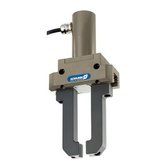
Design and description 4 Design and description 4.1 Design 2-finger parallel gripper with hybrid cable Ground connection EMC fitting Housing Hybrid cable for connection to controller Air purge connection 2-finger parallel gripper with Y-plug Ground connection Y-plug Housing Encoder connection Air purge connection Power connection EMC fitting... -
Page 24: Description
The product is a servo-electric 2-finger parallel gripper with high gripping force and payloads due to multi-tooth guidance. The product is controlled by an external controller. Optimal application utilization is achieved with the SCHUNK ECM controller. 4.3 Functional principle All possible parameters are described in the document relating to the SCHUNK Drive Protocol, see Drive Protocol document. -
Page 25: Assembly
Assembly 5 Assembly 5.1 Assembling and connecting DANGER Risk of fatal injury due to electric current! Touching live parts possess an immediate risk of fatal injury by electrocution. Prior to commencing work, restore the regulator to a de- energized state. ð... - Page 26 Assembly Both variants Logic and motor voltage are disconnected from the controller. The intermediate circuit voltage has dropped to a residual voltage of less than 10 V. Check the flatness of the mounting surface, [/ 27]. } 5.2.1 Screw the product to the machine/system, [/ 27].
-
Page 27: Connections
Assembly 5.2 Connections 5.2.1 Mechanical connection Evenness of the The values apply to the whole mounting surface to which the mounting surface product is mounted. Edge length Permissible unevenness < 100 < 0.02 > 100 < 0.05 Tab.: Requirements for evenness of the mounting surface (Dimensions in mm) Choose the installation position so that connection cables are not damaged or cannot wrap around the product when swiveling. - Page 28 Assembly Assembly of the product Assembly options Item Mounting Side A Mounting screws Max. depth of engagement [mm] Mounting screws as per DIN EN ISO 4762 standard Centering sleeve Ø 8 Ø 10 Ø 14 Side B Bore hole for mounting screws Centering sleeve Ø...
-
Page 29: Electrical Connection To The Ecm Controller
Black Motor phases White (*) Wire color of the supplied SCHUNK cable, otherwise according to customer specifications Tab.: Pin allocation terminal strip motor at drive regulator ECM 13.00 | EGN | Assembly and Operating Manual | en | 389056... - Page 30 Cos- - Cos Osz+ White/Red + Ref White/Yellow - Ref (*) Wire color of the supplied SCHUNK cable, otherwise according to customer specifications Tab.: Pin allocation terminal strip resolver at drive regulator ECM Variant with Connection Plug connector EGN-S Y-plug...
- Page 31 White unassigned unassigned unassigned Outer shield (*) Wire color of the supplied SCHUNK cable, otherwise according to customer specifications Tab.: Pin allocation connection plug M17 on stranded wires 13.00 | EGN | Assembly and Operating Manual | en | 389056...
- Page 32 Assembly 5.2.2.2 Wiring diagram Wiring diagram 13.00 | EGN | Assembly and Operating Manual | en | 389056...
- Page 33 Assembly 5.2.2.3 External protection CAUTION Risk of damage to the controller! If the power circuit of the controller is too high or not protected, the controller may be damaged. Protect the power circuit of the ECM controller with maximum 6 A. The power circuit of the ECM controller must be protected by the customer.
- Page 34 Assembly Protection via current limiting of the supplying power supply unit The power supply unit must comply with the technical data given in the following table. The following power supply unit manufactured by PULS is recommended: Manufacturer's code DIMENSION QS5.241 Type Clocked Connections...
-
Page 35: Connecting The Ground Cable (Functional Ground)
Assembly 5.3 Connecting the ground cable (functional ground) Ground connection Screw * Toothed lock washer Washer Product Cable lug Ground marking *) Tightening torque: 5 Nm A ground connection with a sufficient cross-section must be established between the product and the machine on the customer's premises. -
Page 36: Air Purge Connection For Dust-Tight (Sd) Variant
Assembly 5.4 Air purge connection for dust-tight (SD) variant Item Mounting Thread in air purge connection Maximum depth of engagement [mm] (from locating surface) CAUTION Property damage due to incorrect assembly! If the dust-tight (SD) variant is operated without air purge, neither the function nor permanent tightness can be guaranteed. -
Page 37: Start-Up And System Integration Via Ecm Controller
Start-up and system integration via ECM controller 6 Start-up and system integration via ECM controller NOTE See Assembly and Operating Manual "ECM Controller" for instructions on start-up and system integration of the product via the ECM controller. 13.00 | EGN | Assembly and Operating Manual | en | 389056... -
Page 38: Troubleshooting
If the shaft now rotates but the jaws do not move, then the spindle is damaged. The product can only be repaired at the factory! Send the product to SCHUNK with a repair order. Motor connected incorrectly. Check connections on the motor. -
Page 39: Behavior In Event Of Malfunctions On The Ecm Controller
Troubleshooting 7.2 Behavior in event of malfunctions on the ECM controller Identified errors are shown as hexadecimal code on the seven- segment display of the controller. Information about the error codes are included in the software manual, see the "Controller ECM" Assembly and Operating Manual. -
Page 40: Maintenance
} 8.2 [/ 40]. 8.2 Grease/greasing areas Lubricate the product at every maintenance interval so that every greasing area is optimally lubricated with grease. SCHUNK recommends the lubricants listed. Lubricant point Lubricant All seals Rivolta F.L.G. GT-2 Metallic sliding surfaces Rivolta F.L.G. -
Page 41: Maintaining Gripper Without Disassembling
Material damage due to improper disassembly! Incorrect works can cause damage to the mechanics and internal electronics. Disassembly or opening of the product is not permitted. Only allow SCHUNK to repair the product. 13.00 | EGN | Assembly and Operating Manual | en | 389056... -
Page 42: Disassembling And Assembling Dust-Proof Variant
Carry out functional test of the gripper. Sealing kit ID no. 2 x O-ring Installation Installation [mm] dimensions dimensions min. [mm] max. [mm] EGN 80-SD 1316610 Ø 22 x 1.5 0.95 1.35 Ø 22 x 1.0 0.65 EGN 100-SD 1304644 Ø 25 x 1.5 0.95 1.35... - Page 43 0.95 1.35 Tab.: Size of the O-rings Testing the function of the gripper Test function of the gripper with the "Motion Tool SCHUNK (MTS)" configuration and commissioning tool, see enclosed DVD. ð Carry out speed movement with parameters according to the following table.
-
Page 44: Translation Of The Original Declaration Of Incorporation
9 Translation of the original declaration of incorporation in terms of the Directive 2006/42/EG, Annex II, Part 1 Section B. Manufacturer/ SCHUNK SE & Co. KG Distributor Toolholding and workholding | Gripping Technology | Automation technology Bahnhofstr. 106 - 134... -
Page 45: Ukca Declaration Of Incorporation
UKCA declaration of incorporation 10 UKCA declaration of incorporation in accordance with the Supply of Machinery (Safety) Regulations 2008. Manufacturer/ SCHUNK Intec Limited Distributor Clamping and gripping technology 3 Drakes Mews, Crownhill MK8 0ER Milton Keynes We hereby declare that on the date of the declaration the following partly completed machine complied with all basic safety and health regulations found in the "Supply of Machinery (Safety) Regulations 2008". -
Page 46: Information On The Rohs Directive, Reach Regulation And Substances Of Very High Concern (Svhc)
"on the restriction of the use of certain hazardous substances in electrical and electronic equipment (RoHS)", or fulfill their intended function only as part of one. Therefore products from SCHUNK do not fall within the scope of the directive at this time. REACH Regulation Products from SCHUNK fully comply with the regulations of Regulation (EC) No. 1907/2006... - Page 47 13.00 | EGN | Assembly and Operating Manual | en | 389056...
- Page 48 SCHUNK SE & Co. KG Toolholding and workholding | Gripping Technology | Automation technology Bahnhofstr. 106 - 134 D-74348 Lauffen/Neckar Tel. +49-7133-103-0 Fax +49-7133-103-2399 info@de.schunk.com schunk.com Folgen Sie uns I Follow us Wir drucken nachhaltig I We print sustainable...
Need help?
Do you have a question about the EGN 80 and is the answer not in the manual?
Questions and answers