Table of Contents
Advertisement
Quick Links
Advertisement
Table of Contents

Related Manuals for Kuppersbusch EDIP 9650.0


Summary of Contents for Kuppersbusch EDIP 9650.0
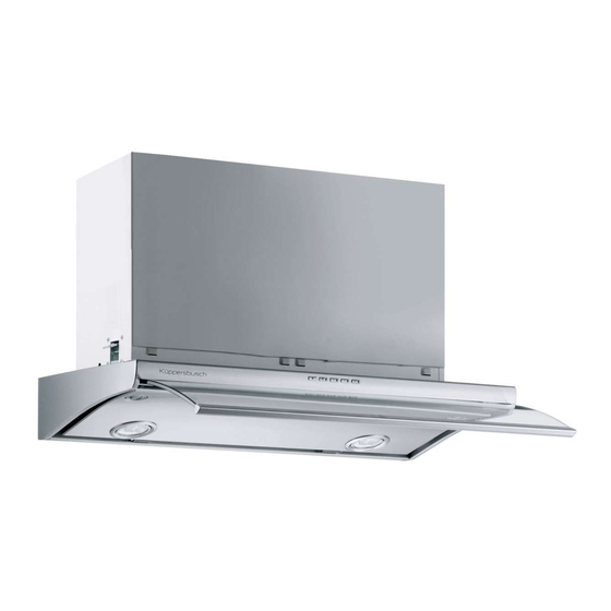
- Page 1 Designer slimline hood EDIP 9650.0/6650.0...
- Page 2 Service Manual: H5-85-01 Responsible: U. Laarmann KÜPPERSBUSCH HAUSGERÄTE AG E-mail: uwe.laarmann@kueppersbusch.de Phone: (0209) 401-732 Kundendienst Fax: (0209) 401-743 Postfach 100132 Date: 1.06.2006 45801 Gelsenkirchen...
-
Page 3: Table Of Contents
Replacing the microswitch................... 16 Replacing the motor .................... 17 5.10 Aligning the glass canopy..................17 Technical data....................... 18 EDIP 6650.0 ......................18 EDIP 9650.0 ......................18 Faults and the cause ....................19 Circuit diagram ......................20 F r i ter a use... -
Page 4: Safety
Service Manual Safety Danger! Repairs may only be carried out by a qualified electrician! Inexpert repairs may lead to risks and damages for the user! It is essential that you observe the following instructions in order to prevent electric shocks: •... -
Page 5: General Information
Service Manual General Information Changing the specification or attempts to modify the product are dangerous. For your own safety spare parts should be installed by an authorised, qualified specialist. The manufacturer accepts no liability for damage which occurs as a result of improper installation or failure to observe currently-valid regulations for this type of application. -
Page 6: Installation
Service Manual Installation General installation instructions Dimensioned drawing Hood type Dimensions A Dimensions B Dimensions C On installing the cooker hood, the following points are to be observed in addition to currently-valid safety instructions and the respective instructions of your country: The cooker hood must always be installed above the centre of the hob. -
Page 7: Installation
Service Manual Installation 3.2.1 Drilling and mounting the supporting plate The hood can be fastened direct underneath the wall units with snap-in holders. Make an opening underneath the wall unit as shown on the drawing. Insert the flange into the top air outlet opening. - Page 8 Service Manual • Now the hood can finally be fastened to the wall unit with the four screws 12a (3.5 x 16) supplied. 14. Install the grease filters again. 15. Re-connect the light plug. 16. Close the glass steam-extraction canopy and hook the Comfort Panel in again.
-
Page 9: Functional Description
Service Manual Functional description The cooker hood has the following features: • Extraction air and recirculating air modes possible (with extras) • Edging suction technology with sound insulation • Electronic push-buttons at the front with 4 power levels • High-power setting •... -
Page 10: Functioning Of The Telescopic Glass Steam-Extraction Canopy
Service Manual Functioning of the telescopic glass steam-extraction canopy The motor cannot be operated when the glass steam-extraction canopy is closed. It is, on the other hand, possible to switch the lamp on and off. If the glass steam-extraction canopy is pulled out, the control panel is released and all of the functions are activated;... -
Page 11: Accessing The Components
Service Manual Accessing the components The individual units Motor compartment Comprises the function elements of the hood: motors, main board and ring transformer for the lamps. Glass telescopic section Extending the glass releases the microswitch so that the appliance can be switched on. Besides serving a design function it also guides steam to the catchment area. -
Page 12: Test Prior To Carrying Out Repairs
Service Manual Test prior to carrying out repairs Before carrying out any repair work, make sure that you carry out the steps contained in the “test” to determine minor errors or faults. Noises or unusual vibrations • Check to ensure that the installation screws are tightly fastened. •... -
Page 13: Changing The Halogen Lamps
Service Manual Changing the halogen lamps If the lighting does not work the lamps will firstly need to be checked and you will need to make sure that the control switch on the control panel of the hood has not developed a fault. Proceed as follows to replace a lamp or lamp mounting: Do not touch the new halogen lamps with your fingers;... -
Page 14: Replacing The Touch Controls
Service Manual Remove the support. Disconnect the transformer connections and remove them; replace with a new transformer with the same properties. Re-assembling is carried out in reverse order. Check the functions. Replacing the touch controls Should you determine that the control panel circuit board is not functioning, replace it as follows: Press the two handles on the side to open up the extraction panel for extraction around the edge. -
Page 15: Replacing The Electronics Unit
Service Manual Remove the two screws that fasten the control panel unit to the casing and take out the control panel. Loosen the screws to release the control panel unit. Open up the control panel, remove the flat wire and take out the circuit board. -
Page 16: Replacing The Microswitch
Service Manual Remove the holders of the terminal strip and take out the circuit board. Replace the circuit board with one of the same properties, observing the appliance circuit diagram. Re-assembling is carried out in reverse order. Check the functions. Replacing the microswitch Proceed as follows to replace the microswitch: Press the two handles on the side to open up the... -
Page 17: Replacing The Motor
Service Manual Replacing the motor The hood is fitted with two motors (one on the right-hand side and one on the left-hand side). Should it become necessary to replace a motor, proceed as follows for the right-hand and for the left-hand side: Remove the cover of the motor compartment. -
Page 18: Technical Data
MAX setting 61 dB (A) INTENSIVE 65 dB (A) Exhaust air connection 150mm Pressure 380 PA EDIP 9650.0 Voltage / frequency 230V / 50Hz Appliance dimensions (W x D x H) 898 x 465 x 280-435mm Electrical connection 420W Halogen lighting... -
Page 19: Faults And The Cause
Faults and the cause Repairs may only be carried out by qualified electricians or specialists! Problem Probable cause Solution The cooker hood does not work. The power cable has not been connected to a live Check to ensure that the cable has been properly socket. -
Page 20: Circuit Diagram
Service Manual Circuit diagram Lamps Microswitch Ribbon cable Control panel F r i ter a use...
Need help?
Do you have a question about the EDIP 9650.0 and is the answer not in the manual?
Questions and answers