Table of Contents
Advertisement
Quick Links
Advertisement
Table of Contents

Related Manuals for Kuppersbusch EDD 9660.0


Summary of Contents for Kuppersbusch EDD 9660.0
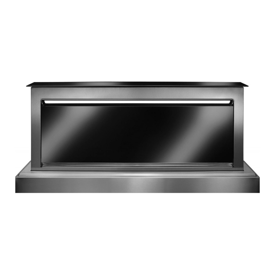
- Page 1 Down-Draft cooker hood EDD 9660.0 Problems and solutions...
- Page 2 Service Manual: H5-51-01 Responsible: U. Laarmann KÜPPERSBUSCH HAUSGERÄTE AG E-mail: uwe.laarmann@kueppersbusch.de Tel.: (0209) 401-732 Customer Service Fax: (0209) 401-743 Postfach 100 132 Date: 28.11.2013 45801 Gelsenkirchen...
-
Page 3: Table Of Contents
Service Manual Inhalt Safety..........................4 The extractable downdraft unit does not open and the suctioning system does not work ......................... 5 Check if the network voltage is working ............... 5 Check if the red power button is in ON position ............ 5 Check if the red power button is in on position............ -
Page 4: Safety
Service Manual Safety Danger! Repairs may only be carried out by a qualified electrician! Improper repairs can be extremely dangerous for the user. It is essential that you observe the following instructions in order to prevent electric shocks: • The casing and the frame may be live in the event of faults! •... -
Page 5: The Extractable Downdraft Unit Does Not Open And The Suctioning System Does Not Work
Service Manual Attention! Connecting the appliance to the mains and repairing and servicing the appliance may only be carried out by a qualified electrician according to currently-valid safety regulations. For your own safety, do not allow anyone other than a qualified service technician to install, service or repair the product. - Page 6 Service Manual • There are only the following 7 wires in the 9-pole connector: Grease filters panel presence buttons PIN 3 PIN 6 BLACK Magnetic safety circuit breaker PIN 4 YELLOW PIN 7 GREY Actuator PIN 9 BROWNN PIN 8 BLUE Ground connection PIN 5...
-
Page 7: Check If The Grease Filters Panel Presence Button Is Working Properly
Service Manual Check if the grease filters panel presence button is working properly The downdraft is equipped with buttons, placed behind the grease filters covering panel which, in case of malfunctioning, prevent the downdraft from starting any functions. • Lift the extractable downdraft unit up, by pressing the on/off key. •... -
Page 8: Check If The Panel Is Unhooked
Service Manual Button pressed = Button released = Contact closed Contact open • Repeat the test by inserting the test prod into pins 3 and 6 of the 9 pole connector, placed in the downdraft lower body. • Repeat the test by inserting the test prod in CN111 connector of the main board, placed in the electrical system box. - Page 9 Service Manual • Disconnect the lamps cable (A), the 9- pole cable (B) and the push-button cable (C). • Remove the brackets which fix the downdraft to the cabinet. • In case of internal motor version, remove the motor fixing screws and remove the suctioning unit.
-
Page 10: Replace The Electrical System Board
Service Manual • Remove the front body panel. • Hook it again, by pressing simultaneously on both sides of the panel. • After having remounted the body front panel, and before placing the downdraft again into the cabinet, we recommend to check the downdraft operation. -
Page 11: Replace The Power Supply Electrical Board
Service Manual • Remove the plastic cover screws. • Remove the fairlead. • Disconnect the connectors one by one, paying special care in reconnecting them properly in the new board. Replace the power supply electrical board • Disconnect power supply. •... -
Page 12: Check The Push-Button Panel Connector Connection Inside The Wiring
Service Manual • Remove the plastic cover. • Disconnect the connectors one by one, paying special care in reconnecting them properly in the new board. Check the push-button panel connector connection inside the wiring • Check if the push-button grey connector in the connectors panel is inserted properly and if there are any bent pins inside the connector. -
Page 13: Suctioning Speeds Do Not Correspond To The Keys Pressed Or Some Speeds Do Not Work At All
Service Manual Suctioning speeds do not correspond to the keys pressed or some speeds do not work at all. Check if the 6-pole suctioning unit connector or the sem power pack connector are connected properly • By using a screwdriver, check if the inner contacts of the fixed connector, placed in the electrical system box, as well as the movable connector, found in the suctioning unit, are all inserted properly. - Page 14 Service Manual • For external motor (EM) version, check the connections accordingly to the following diagram. • In case of connection with sem external power packs, make sure that the 7 m-cable used to connect the cooker hood to the external motor is not cut or damaged (tempered). For internal use only...
- Page 15 Service Manual Check the connections in such a case: External motor without SEM To be connected to the downdraft connection External motor with SEM connection To be connected to the downdraft For internal use only...
-
Page 16: Replace The Suctioning Unit In Case Of Internal Motor Version
Service Manual Replace the suctioning unit in case of internal motor version • Disconnect power supply. • Disconnect the 6-pole cable from the suctioning unit. • Dismount the suctioning unit and replace it with a new one. For internal use only... -
Page 17: Replace The Sem External Power Pack In Case Of External Motor (Em) Version
Service Manual Replace the sem external power pack in case of external motor (em) version • It is necessary to use a new power pack and follow the installation procedure detailed in the SEM installation manual. Attention! Never cut the connecting cable during installation operations! The stainless steel body liner is damaged Replace the body liner •... - Page 18 Service Manual • Lift the downdraft up from the cabinet. • Reconnect the connectors and lift the extractable unit up. • Remove the upper front panel. • Disconnect the flat cable. • Remove the body liner fixing screws placed in the rear and lateral side.
-
Page 19: The Extractable Unit Opens, But The Suctioning System Does Not Work At Any Speed
Service Manual The extractable unit opens, but the suctioning system does not work at any speed Check if the 6-pole suctioning unit connector or the sem power pack connector are connected properly • See Chapter “Check if the suctioning unit 6-pole connector wires in the electrical system board are connected properly”... -
Page 20: Check If The Electro-Mechanic Transformer
Service Manual • Remove the downdraft from the cabinet. • Find the actuator connection in the right side opening of the suctioning unit. • Check if the 2-pole connector for the actuator feeding is inserted properly and that pins inside the connector are crimped properly. Check if the electro-mechanic transformer placed inside the electrical system box is working properly •... -
Page 21: Replace The Actuator
Service Manual Replace the actuator • Remove the suctioning unit or the pipe flange in case of external motor version (see “Check if the red power button is in on position” on page 5). • Disconnect the connectors in the downdraft lower panel. •... -
Page 22: The Touch Control Panel Does Not Light Up
Service Manual • Remove the actuator and replace it with a new one. The touch control panel does not light up Check if the connector is connected properly. Check if the connector inside the extractable unit column is connected properly. •... -
Page 23: Replace The Push-Button Panel
Service Manual Replace the push-button panel. In case of glass front panel version, since the push-button panel is glued in, it is necessary to replace the entire front panel. • Remove the upper front panel. • Disconnect the flat cable. •... -
Page 24: Lighting Does Not Light Up
Service Manual Lighting does not light up Replace the neon lamp (tube) • Remove the upper front panel. • Disconnect the flat cable. • Remove the neon tube and replace it with a new one. • Remount the upper front panel and reconnect the flat cable; then check the neon tube operation. -
Page 25: Check That The Neon Tube Supports
Service Manual Check that the neon tube supports are not damaged and are connected properly. • Unscrew the neon tube support by removing its screws. • Check if wires inside the neon tube holders contacts are inserted properly. • Carry out an electric continuity test between the neon tube holders and the ballast inside the electrical system box. -
Page 26: Replace The Ballast
Service Manual • Disconnect the wires of the neon tube holder to be replaced, by using a suitable tool. • Push the tongues placed in the upper side of the neon tube holder and remove the component by moving it downwards. Replace the ballast. -
Page 27: Configuration Of The Remote Control
Service Manual Configuration of the remote control Procedure. Please proceed as follows: Press button until symbol appears. Press button and keep hold for 5 seconds. The remote control is now configured. For internal use only...
Need help?
Do you have a question about the EDD 9660.0 and is the answer not in the manual?
Questions and answers