
Related Manuals for urmet domus Note 2 1723 Series


Summary of Contents for urmet domus Note 2 1723 Series
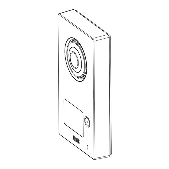
- Page 1 Mod. 1723 DS 1723-024 LBT 20469 ONE- AND TWO-HOUSEHOLD KIT WITH PANEL AND COLOUR 7” HANDS-FREE MONITOR Ref. 1723/71 - 1723/72 (*) IP45 IP45 IK07 IK07 CONFIGURATION BOOKLET...
-
Page 2: Table Of Contents
TABLE OF CONTENTS FIRST SWITCH-ON ..............................3 INSTALLER SETTINGS ............................4 DOOR AND GATE OPENING SETTINGS ......................4 VIDEO SURVEILLANCE SETTING (E.G. FOR A WAITING ROOM) ..............5 HOME AUTOMATION SETTINGS ........................6 BUTTON CONFIGURATION ........................7 BUTTON VISIBILITY ..........................9 BUTTON CONFIGURATION STAIRS LIGHT .................. -
Page 3: First Switch-On
FIRST SWITCH-ON The video door phone shows the language selection menu the fi rst time it is switched on: Tap on the required language and confi rm by tapping on the icon on the bottom right. The following will appear: Set the current date and time It is advisable to select automatic daylight saving time in Europe as well Tap on the... -
Page 4: Installer Settings
Alternatively, open the ‘Confi guration’ menu using the icon on the top right, select the ‘User’ menu and select ‘Date & Time’. The following page will appear: INSTALLER SETTINGS To confi gure the video door phone functions using the ‘Confi guration’ menu, which can be accessed by tapping on the icon on the top right, select the ‘Installer’... -
Page 5: Video Surveillance Setting (E.g. For A Waiting Room)
– Check that dip-switch 5 is in the OFF position (default). – Connect the door lock to terminals SE+ and SE- (timed capacitive discharge). – Connect the two N.O. terminals (low power relay) to the gate opener input (all open). –... -
Page 6: Home Automation Settings
Use the fi rst three lines to specify which are the cameras present to the video door phone: — The one or ones on the call stations (identifi cation: 1 and possibly 2). — The total number of those connected to the interface (identifi cation: 3,4,5,6). —... -
Page 7: Button Configuration
The following will appear: The fi rst two items can be used to confi gure all buttons and to defi ne which will be visible to the user and which will not. The third item can be used to defi ne the function of the Stairs Light button which appears during the call, e.g. to switch on the garden lights. - Page 8 Alternatively, the Yokis buttons can be confi gured without having to use an app: The single Yokis buttons can be confi gured directly by connecting them to the receivers: see how to proceed in Annex A. The single Yokis buttons can be confi gured directly by importing them from an eight-button remote control: see how to proceed in Annex B.
-
Page 9: Button Visibility
Touch Contact 1 or Contact 2 to confi gure the operation, by defi ning: — The name of the button. — The rest condition (Normally Open or Normally Closed contact). — The operative method: Switching of the state each time it is pressed or pulse mode (with confi gurable pulse duration from 1 to 60 seconds). -
Page 10: Button Configuration Stairs Light
BUTTON CONFIGURATION STAIRS LIGHT When answering a video door phone call, the user can press the button to switch on the outside lights on the driveway, possibly in a timed manner, for instance. When the user presses the button, one of 16 confi gured buttons will be activated. During the confi... -
Page 11: Exporting Yokis Buttons To A Remote Control Or Video Door Phone
EXPORTING YOKIS BUTTONS TO A REMOTE CONTROL OR VIDEO DOOR PHONE The confi guration of the eight Yokis buttons can be exported to a Yokis eight-button remote control or to another video door phone. Selecting this item will automatically launch a Wizard. RESETTING ALL ACCESS POINTS TO THE RADIO BUS An access point can be used to control a specifi... - Page 12 Follow the connection diagram below on the master video door phone to connect one or more motion sensors (in series). WARNING. Specifi c settings are required in the ‘Confi guration’ menu to use a motion sensor’ Finally, if you want to provide an alarm signal on a siren (e.g. Urmet siren 1033/414), connect the siren to blue wires (SPARE RELAY ) of the master video door phone.
- Page 13 Whether to send power to the motion sensors, if this installation diagram is chosen — Enable only in presence of motion sensors. Whether to associate a video recording in case of alarm or not: — Video recording can be enabled or not. —...
-
Page 14: Contact Setting
CONTACT SETTING The video door phone has two contacts: — Contact 1 available on the two terminals 0, C. — Contact 2 available on the two blue wires of the connector relay (RELAY SPARE). These contacts can be used in various ways, according to needs. WARNING. -
Page 15: Letterbox Function Setting
LETTERBOX FUNCTION SETTING INSTALLATION ON ONE-FAMILY KIT REF. 1723/71 On the letterbox, position two magnetic contacts near the front fl ap (mail introduction slot) and at the back (mail collection door). The fi rst contact (mail introduction slot) must be connected to the green and white wires of an E2BPP(X). The second contact (mail collection door) must be connected to the brown and white wires of the same E2BPP(X). -
Page 16: Installation On Two-Family Kit Ref. 1723/72
INSTALLATION ON TWO-FAMILY KIT REF. 1723/72 On each letterbox, of both apartments (0,1) position two magnetic contacts near the front fl ap (mail introduction fl ap) and at the back (mail collection door). Apartment Description of the magnetic contact Connection of the magnetic contact to number function the E4BPP(X) transmitter on the wires:... -
Page 17: Thermostat Setting
STEP 2: SET LETTERBOX MODE ON TRANSMITTER On the transmitter, press rapidly 10 times (Confi guration Menu ) and check that the LED starts fl ashing. Press rapidly 32 times ( ) and check that the LED confi rms at the end by fl ashing twice. At this point, the transmitter is locked in LETTERBOX mode (11) STEP 3: SETTING LETTERBOX MODE ON THE KIT PANEL... -
Page 18: Ending Configuration
ENDING CONFIGURATION In the ‘Confi guration’ menu which can be opened using the icon on the top right, select the ‘Installer’ menu, type in the password (‘1937’) and select ‘Thermostat Settings’. When the thermostat is activated, two other lines appear which can be used to: —... -
Page 19: Office With Attached Home Setting
The indication of the two selected buttons will now appear on the line (12) (13) OFFICE WITH ATTACHED HOME SETTING In some situations, the user may have an offi ce downstairs and live upstairs. In these cases, you will need two separate call buttons for: —... -
Page 20: Automatic Door Opener Setting
when a call is made using the lower button, both video door phones will ring and the message will appear: ‘PANEL 1: #1’ Remember that the writing with the name of the panel (default ‘PANEL’) can customised by the installer in the ‘Confi... - Page 21 Remove the tick from the ‘Auto Door Opening’ option. In this way, the button will no longer be visible on the Home Page. DS1723-024...
-
Page 22: Test
TEST VIDEO DOOR PHONE CALL TEST Make a video door phone call by pressing the Call button: The icon lights up to indicate that the call was sent. The following will appear on the video door phones in the system: PANEL 1 Also without answering, the door can be opened by using either: —... - Page 23 After a call (before starting the conversation or during the conversation itself) is also possible: • To change the image format from 4:3 to 16:9 or vice versa To do this, tap on the icon . When 16:9 format is selected, the camera will frame the upper part of the scene. The frame can be moved by sliding the image with your fi...
-
Page 24: Camera Control Test
touched) by taping on the icon Finally, during conversation, you can mute/unmute the microphone so that the visitor cannot hear you by pressing the button CAMERA CONTROL TEST Switch on the video door phone by tapping on the screen or the button Tap on the camera control button: The video door phone will show the image from the panel camera, also providing the possibility to open the door or start a conversation:... -
Page 25: Alarm Function Test
will automatically appear on the camera after the programmed cycle time. The user can disable or re-enable cyclic view display by tapping the icon at any time. Tap on the icon to start recording a video clip. If cyclic transition between cameras is enabled, video clip recording is considered a priority. Therefore, the switch to the next camera can only happen at the end of the video clip recording, whereby allowing the user to record everything they want. -
Page 26: Past Alarm Signalling (Alarm Memory)
It is possible to: — Send a notifi cation to an external siren. — Activate a specifi c home automation scenario (e.g. the garden lights). — Send the remote alarm signal, by means of a call sending device (the CallMe app, in this case). This indication generates a push notifi... -
Page 27: How To Browse The Alarm History
The icon on the left can be used to quickly recognise the recording type: indicates a video clip saved in the event of alarm, indicates a video clip recorded from the panel using the video door phone function or manually during a call, the icon indicates a video clip recorded by additional camera. -
Page 28: How To Save The Alarm History
The alarm history can be browsed on CallMe app following a similar method (17) WARNING. Since the call sending device, after sending an alarm notifi cation, masks any other sending for 10 minutes, the alarm history may contain a fewer alarms than those present on the master video door phone. -
Page 29: Letterbox Function Test
After writing, the icon turns black on white background again: the microSD card can be removed. The alarm history will be stored in a folder on the microSD card named ‘LOGS’. If the folder does not exist, it will be created automatically before writing the fi le. This is a text fi... -
Page 30: Office With Attached Home Setting
OFFICE WITH ATTACHED HOME SETTING Make a video door phone call by pressing the upper Call button: The icon lights up to indicate that the call was sent. The following appears on the video door phones in the home and in the offi ce: PANEL 1: #0 PANEL 1: #0 All the call related functions will be available in standard confi... -
Page 31: Updating The Video Door Phone Software
The following appears on the video door phones in the home and in the offi ce: PANEL 1: #1 PANEL 1: #1 All the call related functions will be available in standard confi guration. See the VIDEO DOOR PHONE CALL TEST section. -
Page 32: Access Control
ACCESS CONTROL The kit comprises 5 transponder keys and 2 chip tags for electric lock activation. The chip tag is the sensor contained inside the keys and can be attached to various objects of daily use (keyholder, cell phone, watch. etc.). To open the door, move a key or the object to which the chip tag has been attached close to the name tags area of the call station (the correct point is indicated with ) as shown to the side. -
Page 33: Key Cancellation Procedure
KEY CANCELLATION PROCEDURE To cancel the keys programmed: 1. Move the Master key close to the call station. 2. The call station emits a confi rmation beep. 3. Hold the Master key in front of icon for at least 5 seconds. 4. -
Page 34: Annexes
ANNEXES ANNEX A How to confi gure Yokis buttons from the video door phone (without using the Yokis PRO app). In this operating mode, you can confi gure the Yokis buttons (virtual) directly from the video door phone. The advantage is that a wizard interface can be used to simplify operations: the video door phone automatically manages the pulses needed to confi... - Page 35 Select ‘Confi gure Buttons’ to go to the following page: The Yokis buttons are the fi rst 8 on top. Tap on the Yokis button you want to confi gure. Five items will appear: DS1723-024...
- Page 36 Select the fi rst item, ‘Set Button Name’, to assign a mnemonic name to the button using the keyboard: Select ‘OK’ to confi rm. Some background information may be useful before describing the remaining four items in detail. The button confi guration procedure is similar to that of the buttons of a Yokis eight-button remote control. The video door phone automatically sends the pulses needed for the confi...
- Page 37 This opens a submenu for connecting the button to one or more receivers. Connect (or Disconnect) E5 R1 This is used to logically ‘connect’ the button to a receiver. In direct mode, one or more receivers, up to four can be connected (connecting a fi fth receiver will replace the fourth one).
- Page 38 One of four possible operating modes can be defi ned for the button: — Toggle (lighting), Dim/Off (dimmer), Up/Stop/Down (shutters) — On (lighting), Up & Stop (shutters) — Off (lighting), Down & Stop (shutters) — Memory, Go to position (shutters) For more information, see the Yokis ‘Radio Quick Installation Guide’, para.
- Page 39 If Radio Bus mode is selected, a new ‘Lighting/Shutters’ menu item will appear for selecting whether the centralisation operates the lighting (default) or the shutters or both: Select ‘Lighting/Shutters’ you can choose one of three options: Lights M 10 o Shutters M 11 or Lighting/Shutters For more information, see the Yokis ‘Radio Quick Installation Guide’, para.
- Page 40 Using the keyboard, defi ne the number of pulses to be sent to the receiver module with the specifi c button, e.g. to confi gure the receiver timing. Then press ‘Enter’ and wait for the notifi cation of the receiver, typically shown on the receiver (fl...
-
Page 41: Annex B
ANNEX B How to import Yokis Buttons from remote control (or other video door phone) The procedure consists of three steps: 1) Use a Yokis eight-button remote control and confi gure the buttons. See the Yokis ‘Radio Quick Installation Guide’ for more information. 2) Check that all confi... - Page 42 The screen showing all the buttons will appear: Tap on the Yokis button you want to rename and check (one of the fi rst 8 on top). The following will appear: The new icon on the right part of the video door phone indicates that it is a ‘Imported Button’. At this point, you can: —...
-
Page 43: Annex C
ANNEX C How to confi gure the composite buttons The composite buttons can be used to control multiple Yokis buttons at the same time. In practice, for the end user, pressing a composite button will be equal to pressing the single Yokis buttons it consists of in sequence. IMPORTANT The scenarios which can be achieved with the Yokis buttons, e.g. - Page 44 Select ‘Confi gure Buttons’ to go to the following page: The composite buttons are characterised by the default name ‘COMP.BTN N’ and are located in the third and fourth row (the two on the left). There are six in total. Tap on the composite button you want to confi...
- Page 45 From here you can set four parameters: — The name of the button (that the user will see). — The Yokis buttons which will be part of the composition. Tap on all those desired (at least 2): — ‘Delay Between Buttons’. The following page will appear: Here you can choose a waiting time between the functions of the single buttons forming the composite.
- Page 46 — The order with which the selected buttons will be activated in sequence from the fi rst to the last or from the last to the fi rst: DS1723-024...
- Page 47 DS1723-024...
- Page 48 DS 1723-024 LBT 20469 URMET S.p.A. Area tecnica 10154 TORINO (ITALY) servizio clienti +39 011.23.39.810 VIA BOLOGNA 188/C http://www.urmet.com Telef. +39 011.24.00.000 (RIC. AUT.) e-mail: info@urmet.com +39 011.24.00.300 - 323 MADE IN CHINA...
Need help?
Do you have a question about the Note 2 1723 Series and is the answer not in the manual?
Questions and answers