Table of Contents
Advertisement
Quick Links
SENECA
S
Z-PC Line
Z-PC Line
EN
EN
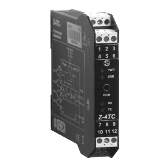
4 TERMOCOUPLE INPUTS Module
4 TERMOCOUPLE INPUTS Module
Installation
Installation
Manual
Manual
Contents:
- General specifications
- Technical features
- Modbus connections rules
- Installation rules
- Electrical connections
- DIP-switches settings
- Main MODBUS registers
- LED signallings
- Purchase order codes
- Factory settings
- Module layout
- Decommissioning and disposal
SENECA s.r.l.
Via Austria, 26 – 35127 – PADOVA – ITALY
Tel. +39.049.8705355 - 8705359 - Fax +39.049.8706287
For manuals and configuration software, please see: www.seneca.it
This document is property of SENECA srl. Duplication and reprodution are forbidden, if not authorized.
Contents of the present documentation refers to products and technologies described in it. All technical
data contained in the document may be modified without prior notice Content of this documentation is
subject to periodical revision.
Z-4TC-1
Z-4TC-1
with Modbus RS485
with Modbus RS485
MI003630-E
ENGLISH 1/8
Advertisement
Table of Contents

Related Manuals for Seneca Z-4TC-1


Summary of Contents for Seneca Z-4TC-1
- Page 1 Tel. +39.049.8705355 - 8705359 - Fax +39.049.8706287 For manuals and configuration software, please see: www.seneca.it This document is property of SENECA srl. Duplication and reprodution are forbidden, if not authorized. Contents of the present documentation refers to products and technologies described in it. All technical data contained in the document may be modified without prior notice Content of this documentation is subject to periodical revision.
-
Page 2: General Specifications
1500 V isolated inputs compared with other low voltage circuits Easy connections for power supply and serial communication by seneca bus that can be mounted on standard DIN rail IEC EN 60715. Removable terminals with section of 2.5 mm ... - Page 3 Power supply Voltage 10 – 40 V; 19 - 28 V 50 – 60 Hz Consumption Typical: 0.5 W, Maximum: 1 W Environmental condition Temperature -10 – +65°C Humidity 30 – 90% a 40°C not condensing Storage Temperature -20 –...
-
Page 4: Installation Rules
MODBUS CONNECTIONS RULES 1) Connect the module into the DIN rail IEC EN 60715 (max 120 2) Please use cables with a suitable length to connect the remote modules. The following table contains information data on the allowed cable lengths: -Bus Length: MODBUS Maximum bus length depending on the Baud Rate. -
Page 5: Electrical Connections
ELECTRICAL CONNECTIONS Power supply and Modbus interface Power Supply and Modbus interface are available by using the bus for the Seneca DIN rail, by the rear IDC10 connector or by Z-PC-DINAL2-17.5 accessory. Power supply The supply voltage must be between 10 and 40 V (Any polarity), ... -
Page 6: Parameters Settings
RS232 RS232 port can be used to communicate and also to program the module. Z-NET or EASY Z-PC are the Seneca configuration softwares. RS232 serial communication port use the following communication parameters : 2400,8,N,1 RS232 and RS485 port use the same Modbus protocol. -
Page 7: Dip-Switches Setting
DIP-SWITCHES SETTING DIP-Switches must be set when module is powered down, otherwise, the module may be damaged. The DIP-switches positions define the Modbus communication parameters: Address and Baud rate. In the following table the Baud rate and address value are depending from the DIP-switches positions: BAUD SW1 POSITION ADDRES... -
Page 8: Factory Setting
10 11 12 Variations of standard parameters are possible by using configuration softwares Z-NET or EASY-Z-PC available at: www.seneca.it site. For more information about a list of all register and their function please see the USER manual. DECOMMISSIONING AND DISPOSAL Disposal of Electrical &...
Need help?
Do you have a question about the Z-4TC-1 and is the answer not in the manual?
Questions and answers